
User Guide
Page 2
... void the user's authority to operate the equipment. VOIR LA NOTICE D'INSTALLATION AVANT DE RACCORDER AU RESEAU. Operation of the FCC rules. Micro-Star International MS-6728 ii These limits are designed to provide reasonable protection against harmful interference when the equipment is likely to correct the interference at his own expense...
... void the user's authority to operate the equipment. VOIR LA NOTICE D'INSTALLATION AVANT DE RACCORDER AU RESEAU. Operation of the FCC rules. Micro-Star International MS-6728 ii These limits are designed to provide reasonable protection against harmful interference when the equipment is likely to correct the interference at his own expense...

User Guide
Page 8
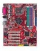
Getting Started Chapter 1. The 865PE/G Neo3 is based on Intel® 865PE/G & ICH5/5R chipsets for choosing the 865PE/G Neo3 (MS-6728) v3.X ATX mainboard. Designed to fit the advanced Intel® Pentium 4 Prescott LGA775 processor, the 865PE/G Neo3 delivers a high performance and professional desktop platform solution. 1-1 Getting Started Getting Started Thank you for optimal system efficiency.
Getting Started Chapter 1. The 865PE/G Neo3 is based on Intel® 865PE/G & ICH5/5R chipsets for choosing the 865PE/G Neo3 (MS-6728) v3.X ATX mainboard. Designed to fit the advanced Intel® Pentium 4 Prescott LGA775 processor, the 865PE/G Neo3 delivers a high performance and professional desktop platform solution. 1-1 Getting Started Getting Started Thank you for optimal system efficiency.

User Guide
Page 9
... processor or higher speed. (For the latest information about CPU, please visit http://www.msi.com.tw/program/ products/mainboard/mbd/pro_mbd_cpu_support.php) Chipset h Intel® 865PE/G chipset - h Supports up to four Ultra ATA drives. Supports both ACPI and legacy...(USB2.0) controller, 480Mb/sec, 8 ports. - 2 Serial ATA/150 ports. - 2 channel Ultra ATA 100 bus Master IDE controller. - MS-6728 ATX Mainboard Mainboard Specifications CPU h Supports Intel® Pentium 4 Prescott LGA775 processors in ICH5/ICH5R. - Supports AGP 8X interface. - Integrated graphics controller ...
... processor or higher speed. (For the latest information about CPU, please visit http://www.msi.com.tw/program/ products/mainboard/mbd/pro_mbd_cpu_support.php) Chipset h Intel® 865PE/G chipset - h Supports up to four Ultra ATA drives. Supports both ACPI and legacy...(USB2.0) controller, 480Mb/sec, 8 ports. - 2 Serial ATA/150 ports. - 2 channel Ultra ATA 100 bus Master IDE controller. - MS-6728 ATX Mainboard Mainboard Specifications CPU h Supports Intel® Pentium 4 Prescott LGA775 processors in ICH5/ICH5R. - Supports AGP 8X interface. - Integrated graphics controller ...

User Guide
Page 11
... JDB1 BIOS IDE 2 IDE 1 Codec PCI Slot 4 PCI Slot 5 JAUD1 J BAT 1 VIA VT6307 SFAN1 SFAN2 JUSB2 JUSB1 J1394_1 J1394_2 JFP2 JFP1 JIR1 865PE/G Neo3 (MS-6728) v3.X ATX Mainboard 1-4 AT X Power Supply FDD 1 MS-6728 ATX Mainboard Mainboard Layout DIMM 1 DIMM 2 DIMM 3 DIMM 4 Top : mouse Bottom: keyboard Top : Parallel Port Bottom: COM A VGA Port (Optional) CP UFA N1...
... JDB1 BIOS IDE 2 IDE 1 Codec PCI Slot 4 PCI Slot 5 JAUD1 J BAT 1 VIA VT6307 SFAN1 SFAN2 JUSB2 JUSB1 J1394_1 J1394_2 JFP2 JFP1 JIR1 865PE/G Neo3 (MS-6728) v3.X ATX Mainboard 1-4 AT X Power Supply FDD 1 MS-6728 ATX Mainboard Mainboard Layout DIMM 1 DIMM 2 DIMM 3 DIMM 4 Top : mouse Bottom: keyboard Top : Parallel Port Bottom: COM A VGA Port (Optional) CP UFA N1...

User Guide
Page 16
...the accompanying CPU Clip and rotate it to make sure the CPU has a cooler attached on the top to protect the CPU contact from damage. MSI Reminds You... 1. Do not touch the CPU socket pins to install the CPU & cooler correctly. Wrong installation will cause the damage of your...before installing the heat sink/cooler fan for the same direction as the CPU (Pin 1 indicator, the red triangle is down) together. 4. MS-6728 ATX Mainboard CPU & Cooler Installation When you do not forget to apply some silicon heat transfer compound on CPU before turning on the computer. The availability...
...the accompanying CPU Clip and rotate it to make sure the CPU has a cooler attached on the top to protect the CPU contact from damage. MSI Reminds You... 1. Do not touch the CPU socket pins to install the CPU & cooler correctly. Wrong installation will cause the damage of your...before installing the heat sink/cooler fan for the same direction as the CPU (Pin 1 indicator, the red triangle is down) together. 4. MS-6728 ATX Mainboard CPU & Cooler Installation When you do not forget to apply some silicon heat transfer compound on CPU before turning on the computer. The availability...

User Guide
Page 18
... on it) to avoid damaging. 3. Whenever CPU is 20 cycles. Therefore we suggest you do not plug/unplug the CPU too often. 2-6 locking switch MSI Reminds You... 1. MS-6728 ATX Mainboard 11. Check the information in PC Health Status in Figure 1) to lock the hooks. 16. Press the four hooks down the load lever...
... on it) to avoid damaging. 3. Whenever CPU is 20 cycles. Therefore we suggest you do not plug/unplug the CPU too often. 2-6 locking switch MSI Reminds You... 1. MS-6728 ATX Mainboard 11. Check the information in PC Health Status in Figure 1) to lock the hooks. 16. Press the four hooks down the load lever...

User Guide
Page 20
...128MB~1GB DIMM3 (Ch B) 128MB~1GB 128MB~1GB DIMM4 (Ch B) 128MB~1GB 128MB~1GB System Density 256MB~2GB 256MB~2GB 512MB~4GB MSI Reminds You... MSI Reminds You... You can barely see the golden finger if the module is deeply inserted in the socket. The DDR DIMM has only ... DIMM memory module vertically into the DIMM slot. Dual-channel DDR works ONLY in the 3 combinations listed in the socket. 3. Volt Notch 2-8 MS-6728 ATX Mainboard Please refer to the following table for detailed dual-channel DDR. Other combination not listed below will only fit in the right orientation. 2. ...
...128MB~1GB DIMM3 (Ch B) 128MB~1GB 128MB~1GB DIMM4 (Ch B) 128MB~1GB 128MB~1GB System Density 256MB~2GB 256MB~2GB 512MB~4GB MSI Reminds You... MSI Reminds You... You can barely see the golden finger if the module is deeply inserted in the socket. The DDR DIMM has only ... DIMM memory module vertically into the DIMM slot. Dual-channel DDR works ONLY in the 3 combinations listed in the socket. 3. Volt Notch 2-8 MS-6728 ATX Mainboard Please refer to the following table for detailed dual-channel DDR. Other combination not listed below will only fit in the right orientation. 2. ...

User Guide
Page 22
... Definition PIN SIGNAL DESCRIPTION 1 Mouse/Keyboard Data Mouse/Keyboard data 2 NC No connection 3 GND Ground 4 VCC +5V 5 Mouse/KeyboardClock Mouse/Keyboardclock 6 NC No connection 2-10 MS-6728 ATX Mainboard Back Panel The back panel provides the following connectors: Mouse Parallel S/PDIF LAN L-In RS-Out Keyboard COM A VGA port (Optional) USB Ports L-Out...
... Definition PIN SIGNAL DESCRIPTION 1 Mouse/Keyboard Data Mouse/Keyboard data 2 NC No connection 3 GND Ground 4 VCC +5V 5 Mouse/KeyboardClock Mouse/Keyboardclock 6 NC No connection 2-10 MS-6728 ATX Mainboard Back Panel The back panel provides the following connectors: Mouse Parallel S/PDIF LAN L-In RS-Out Keyboard COM A VGA port (Optional) USB Ports L-Out...

User Guide
Page 24
... 4-/5.1-/7.1- S/PDIF Out-Coaxial Line In Line Out MIC Rear Speaker Out (in 7.1CH / 5.1CH) Center/Subwoofer Speaker Out ( in 7.1CH / 5.1CH) S/PDIF Out-Optical MSI Reminds You... MS-6728 ATX Mainboard Serial Port Connector The mainboard offers one 9-pin male DIN connector as the serial port. The port is a 16550A high speed communication port...
... 4-/5.1-/7.1- S/PDIF Out-Coaxial Line In Line Out MIC Rear Speaker Out (in 7.1CH / 5.1CH) Center/Subwoofer Speaker Out ( in 7.1CH / 5.1CH) S/PDIF Out-Optical MSI Reminds You... MS-6728 ATX Mainboard Serial Port Connector The mainboard offers one 9-pin male DIN connector as the serial port. The port is a 16550A high speed communication port...

User Guide
Page 26
... 18 GND Ground 19 GND Ground 20 GND Ground 21 GND Ground 22 GND Ground 23 GND Ground 24 GND Ground 25 GND Ground 2-14 MS-6728 ATX Mainboard Parallel Port Connector: LPT1 The mainboard provides a 25-pin female centronic connector as LPT.
... 18 GND Ground 19 GND Ground 20 GND Ground 21 GND Ground 22 GND Ground 23 GND Ground 24 GND Ground 25 GND Ground 2-14 MS-6728 ATX Mainboard Parallel Port Connector: LPT1 The mainboard provides a 25-pin female centronic connector as LPT.

User Guide
Page 28
... The new interface is onethird faster than earlier record-breaking Ultra ATA/100 technology and is backward compatible with the existing Ultra ATA interface. MS-6728 ATX Mainboard ATA100 Hard Disk Connectors: IDE1 & IDE2 The mainboard has a 32-bit Enhanced PCI IDE and Ultra DMA 66/100 controller that ... Slave drive. If you install two hard disks on cable, you must configure second hard drive to Slave mode by setting the jumper accordingly. MSI Reminds You... IDE1 can also connect a Master and a Slave drive. IDE2 IDE1 IDE1 (Primary IDE Connector) The first hard drive should always ...
... The new interface is onethird faster than earlier record-breaking Ultra ATA/100 technology and is backward compatible with the existing Ultra ATA interface. MS-6728 ATX Mainboard ATA100 Hard Disk Connectors: IDE1 & IDE2 The mainboard has a 32-bit Enhanced PCI IDE and Ultra DMA 66/100 controller that ... Slave drive. If you install two hard disks on cable, you must configure second hard drive to Slave mode by setting the jumper accordingly. MSI Reminds You... IDE1 can also connect a Master and a Slave drive. IDE2 IDE1 IDE1 (Primary IDE Connector) The first hard drive should always ...

User Guide
Page 30
Do not use. JFP2 Pin Definition PIN SIGNAL 1 GND 3 SLED 5 PLED 7 NC PIN SIGNAL 2 SPK- 4 BUZ+ 6 BUZ- 8 SPK+ 2-18 MS-6728 ATX Mainboard Front Panel Connectors: JFP1 & JFP2 The mainboard provides two front panel connectors for electrical connection to GND Reserved. JFP1 is compliant with Intel® ...
Do not use. JFP2 Pin Definition PIN SIGNAL 1 GND 3 SLED 5 PLED 7 NC PIN SIGNAL 2 SPK- 4 BUZ+ 6 BUZ- 8 SPK+ 2-18 MS-6728 ATX Mainboard Front Panel Connectors: JFP1 & JFP2 The mainboard provides two front panel connectors for electrical connection to GND Reserved. JFP1 is compliant with Intel® ...

User Guide
Page 32
Early Chipset Initialization Memory Detection Test - Decompressing BIOS image to the screen. 2-20 Testing VGA BIOS - MS-6728 ATX Mainboard D-Bracket™ 2 1 2 3 4 Red Green D-Bracket™ 2 Description System Power ON - Testing onboard memory size. The D-LED will hang if the memory module is damaged or not installed properly. The D-LED will hang here if the processor is damaged or not installed properly. Initializing Keyboard Controller. This will start writing VGA sign-on message to RAM for fast booting.
Early Chipset Initialization Memory Detection Test - Decompressing BIOS image to the screen. 2-20 Testing VGA BIOS - MS-6728 ATX Mainboard D-Bracket™ 2 1 2 3 4 Red Green D-Bracket™ 2 Description System Power ON - Testing onboard memory size. The D-LED will hang if the memory module is damaged or not installed properly. The D-LED will hang here if the processor is damaged or not installed properly. Initializing Keyboard Controller. This will start writing VGA sign-on message to RAM for fast booting.

User Guide
Page 34
MS-6728 ATX Mainboard IEEE 1394 Connectors: J1394_1, J1394_2 (Optional) The mainboard provides two 1394 pin headers that allow you to connect IEEE 1394 ports via an external IEEE1394 bracket. 9 1 10 2 J1394_1, J394_2 Pin Definition PIN SIGNAL PIN 1 TPA+ 2 3 Ground 4 5 TPB+ 6 7 Cable power 8 9 Key (no pin) 10 SIGNAL TPAGround TPBCable power Ground IEEE1394 Bracket Foolproof Design 2-22
MS-6728 ATX Mainboard IEEE 1394 Connectors: J1394_1, J1394_2 (Optional) The mainboard provides two 1394 pin headers that allow you to connect IEEE 1394 ports via an external IEEE1394 bracket. 9 1 10 2 J1394_1, J394_2 Pin Definition PIN SIGNAL PIN 1 TPA+ 2 3 Ground 4 5 TPB+ 6 7 Cable power 8 9 Key (no pin) 10 SIGNAL TPAGround TPBCable power Ground IEEE1394 Bracket Foolproof Design 2-22

User Guide
Page 36
... 2 VCC 3 USB0- 4 USB1- 5 USB0+ 6 USB1+ 7 GND 8 GND 9 Key (no pin) 10 USBOC MSI Reminds You... JCD1 R GND L Chassis Intrusion Switch Connector: JCI1 This connector is opened, the switch will record this status and show a warning message on the screen. MS-6728 ATX Mainboard CD-In Connector: JCD1 The connector is ideal for CD-ROM...
... 2 VCC 3 USB0- 4 USB1- 5 USB0+ 6 USB1+ 7 GND 8 GND 9 Key (no pin) 10 USBOC MSI Reminds You... JCD1 R GND L Chassis Intrusion Switch Connector: JCI1 This connector is opened, the switch will record this status and show a warning message on the screen. MS-6728 ATX Mainboard CD-In Connector: JCD1 The connector is ideal for CD-ROM...

User Guide
Page 38
... card. The PCI IRQ pins are hardware lines over which devices can send interrupt signals to make sure that you unplug the power supply first. MS-6728 ATX Mainboard Slots The mainboard provides one AGP slot and five 32-bit PCI bus slots.
... card. The PCI IRQ pins are hardware lines over which devices can send interrupt signals to make sure that you unplug the power supply first. MS-6728 ATX Mainboard Slots The mainboard provides one AGP slot and five 32-bit PCI bus slots.

User Guide
Page 40
... activate the boot menu similar to boot up. 3-2 You may also restart the system by too quickly for you want to trigger the boot menu. MS-6728 ATX Mainboard Entering Setup Power on the computer and the system will list all the bootable devices. When the message below appears on the screen, press...
... activate the boot menu similar to boot up. 3-2 You may also restart the system by too quickly for you want to trigger the boot menu. MS-6728 ATX Mainboard Entering Setup Power on the computer and the system will list all the bootable devices. When the message below appears on the screen, press...

User Guide
Page 42
... entry appears if your system's performance. Advanced Chipset Features Use this menu to specify your settings for basic system configurations, such as time, date etc. MS-6728 ATX Mainboard The Main Menu Once you enter AMIBIOS NEW SETUP UTILITY, the Main Menu will appear on the screen. Power Management Features Use this menu...
... entry appears if your system's performance. Advanced Chipset Features Use this menu to specify your settings for basic system configurations, such as time, date etc. MS-6728 ATX Mainboard The Main Menu Once you enter AMIBIOS NEW SETUP UTILITY, the Main Menu will appear on the screen. Power Management Features Use this menu...

User Guide
Page 44
... time format is . The specification of hard disk drive will show up on the right hand according to your selection. month The month from Jan. MS-6728 ATX Mainboard Standard CMOS Features The items inside STANDARD CMOS SETUP menu provide some category, in which include none, one or more setup items. Use the...
... time format is . The specification of hard disk drive will show up on the right hand according to your selection. month The month from Jan. MS-6728 ATX Mainboard Standard CMOS Features The items inside STANDARD CMOS SETUP menu provide some category, in which include none, one or more setup items. Use the...

User Guide
Page 46
... try to boot from other devices if the system fails to boot within 5 seconds since it will skip some check items. Available options: [Enabled], [Disabled]. MS-6728 ATX Mainboard Advanced BIOS Features Quick Boot Setting the item to [Enabled] allows the system to boot from the 1st/2nd/3rd boot device...
... try to boot from other devices if the system fails to boot within 5 seconds since it will skip some check items. Available options: [Enabled], [Disabled]. MS-6728 ATX Mainboard Advanced BIOS Features Quick Boot Setting the item to [Enabled] allows the system to boot from the 1st/2nd/3rd boot device...


