User Guide
Page 5
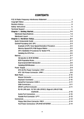
...CPU Fan 2-5 Memory ...2-7 Introduction to DDR SDRAM 2-7 DDR Population Rules 2-7 Dual-channel DDR Introduction 2-8 Installing DDR Modules 2-8 Power Supply ...2-9 ATX 20-Pin Power Connector: ATX1 2-9 ATX 12V Power Connector: JPW1 2-9 Back Panel ...2-10 Mouse Connector 2-10 Keyboard Connector 2-10 Serial Port Connector: COM A 2-11 USB Connectors 2-11...-B Radio Frequency Interference Statement ii Copyright Notice ...iii Revision History ...iii Safety Instructions ...iv Technical Support ...iv Chapter 1. Getting Started 1-1 Mainboard Specifications 1-2 Mainboard Layout 1-4 Chapter 2.
...CPU Fan 2-5 Memory ...2-7 Introduction to DDR SDRAM 2-7 DDR Population Rules 2-7 Dual-channel DDR Introduction 2-8 Installing DDR Modules 2-8 Power Supply ...2-9 ATX 20-Pin Power Connector: ATX1 2-9 ATX 12V Power Connector: JPW1 2-9 Back Panel ...2-10 Mouse Connector 2-10 Keyboard Connector 2-10 Serial Port Connector: COM A 2-11 USB Connectors 2-11...-B Radio Frequency Interference Statement ii Copyright Notice ...iii Revision History ...iii Safety Instructions ...iv Technical Support ...iv Chapter 1. Getting Started 1-1 Mainboard Specifications 1-2 Mainboard Layout 1-4 Chapter 2.

User Guide
Page 7
Designed to fit the advanced Intel® Pentium® 4 processors in 478 pin package, the 865PE Neo2-V / 848P Neo-V Series delivers a high performance and professional desktop platform solution. 1-1 Getting Started Chapter 1. The 865PE Neo2-V / 848P Neo-V Series is based on Intel® 865PE / 848P and ICH5 chipsets for choosing the 865PE Neo2-V / 848P Neo-V Series (MS-6788) v2.X ATX mainboard. Getting Started Getting Started Thank you for optimal system efficiency.
Designed to fit the advanced Intel® Pentium® 4 processors in 478 pin package, the 865PE Neo2-V / 848P Neo-V Series delivers a high performance and professional desktop platform solution. 1-1 Getting Started Chapter 1. The 865PE Neo2-V / 848P Neo-V Series is based on Intel® 865PE / 848P and ICH5 chipsets for choosing the 865PE Neo2-V / 848P Neo-V Series (MS-6788) v2.X ATX mainboard. Getting Started Getting Started Thank you for optimal system efficiency.
User Guide
Page 8
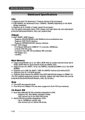
... (for Northwood only) / 533MHz / 800MHz depending on DIMM 1.3). (For the updated supporting memory modules, please visit http://www.msi.com.tw/ program/products/mainboard/mbd/pro_mbd_trp_list.php.) Slots h One AGP slot supports 8x/4x. Supports PIO, Bus Master operation modes. - h Supports two ...DDR 400) for single-channel mode and 6. 4GB/s (DDR 400) for dual-channel mode (for 865PE) memory size without ECC. Can connect up to 2 Serial ATA drives. 1-2 MS-6788 ATX Mainboard Mainboard Specifications CPU h Supports Intel® P4 Northwood / Prescott (Socket 478) processors. PCI Master v2.3....
... (for Northwood only) / 533MHz / 800MHz depending on DIMM 1.3). (For the updated supporting memory modules, please visit http://www.msi.com.tw/ program/products/mainboard/mbd/pro_mbd_trp_list.php.) Slots h One AGP slot supports 8x/4x. Supports PIO, Bus Master operation modes. - h Supports two ...DDR 400) for single-channel mode and 6. 4GB/s (DDR 400) for dual-channel mode (for 865PE) memory size without ECC. Can connect up to 2 Serial ATA drives. 1-2 MS-6788 ATX Mainboard Mainboard Specifications CPU h Supports Intel® P4 Northwood / Prescott (Socket 478) processors. PCI Master v2.3....
User Guide
Page 9
... - Integrated Fast Ethernet MAC and PHY in ICH5. Supports ACPI Power Management. BIOS h The mainboard BIOS provides "Plug & Play" BIOS which records your mainboard specifications. Compliant with AC97 v2.2 Spec. - Dimension h ATX Form Factor: 29.5 cm (L) x 21.0 cm (W). Supports 10Mb/s, 100Mb/s and 1000Mb/s (...chip. - h 6 channels software audio codec ALC655. - LAN (Optional) h Realtek® 8110S/8100C Dual layout. - h The mainboard provides a Desktop Management Interface (DMI) function which detects the peripheral devices and expansion cards of the board automatically.
... - Integrated Fast Ethernet MAC and PHY in ICH5. Supports ACPI Power Management. BIOS h The mainboard BIOS provides "Plug & Play" BIOS which records your mainboard specifications. Compliant with AC97 v2.2 Spec. - Dimension h ATX Form Factor: 29.5 cm (L) x 21.0 cm (W). Supports 10Mb/s, 100Mb/s and 1000Mb/s (...chip. - h 6 channels software audio codec ALC655. - LAN (Optional) h Realtek® 8110S/8100C Dual layout. - h The mainboard provides a Desktop Management Interface (DMI) function which detects the peripheral devices and expansion cards of the board automatically.
User Guide
Page 10
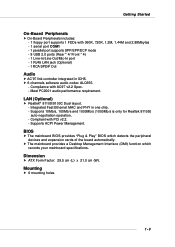
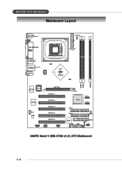
MS-6788 ATX Mainboard Mainboard Layout Top : mouse Bottom: keyboard CP UFAN1 T:SP DIF Out B:USB ports T:LAN jack (Optional) B:USB ports T: L i n e - I n M:Line-Out B:Mic JPW1 ATX Power Supply Intel 865PE chipset DIMM 1 DIMM 2 DIMM 3 Winb ond W83627THF BIOS AGP Slot PCI Slot 1 Realtek 8110S/8100C PCI Slot 2 PCI Slot 3 CD1 Codec JSP1 PCI Slot 4 PCI Slot 5 JAUD1 JDB1 ICH 5 S ATA 2 S ATA 1 IDE 2 IDE 1 SYSFAN1 BATT + USB2 USB3 FDD1 J B AT 1 JFP1 JFP2 865PE Neo2-V (MS-6788 v2.X) ATX Mainboard 1-4
MS-6788 ATX Mainboard Mainboard Layout Top : mouse Bottom: keyboard CP UFAN1 T:SP DIF Out B:USB ports T:LAN jack (Optional) B:USB ports T: L i n e - I n M:Line-Out B:Mic JPW1 ATX Power Supply Intel 865PE chipset DIMM 1 DIMM 2 DIMM 3 Winb ond W83627THF BIOS AGP Slot PCI Slot 1 Realtek 8110S/8100C PCI Slot 2 PCI Slot 3 CD1 Codec JSP1 PCI Slot 4 PCI Slot 5 JAUD1 JDB1 ICH 5 S ATA 2 S ATA 1 IDE 2 IDE 1 SYSFAN1 BATT + USB2 USB3 FDD1 J B AT 1 JFP1 JFP2 865PE Neo2-V (MS-6788 v2.X) ATX Mainboard 1-4
User Guide
Page 11
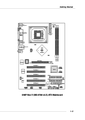
I n M:Line-Out B:Mic JPW1 ATX Power Supply Intel 848P chipset DIMM 1 DIMM 2 Winb ond W83627THF BIOS AGP Slot PCI Slot 1 Realtek 8110S/8100C PCI Slot 2 PCI Slot 3 CD1 Codec JSP1 PCI Slot 4 PCI Slot 5 JAUD1 JDB1 ICH 5 S ATA 2 S ATA 1 IDE 2 IDE 1 SYSFAN 1 BATT + USB2 USB3 FDD1 J B AT 1 JFP1 JFP2 848P Neo-V (MS-6788 v2.X) ATX Mainboard 1-5 Getting Started Top : mouse Bottom: keyboard CP UFAN1 T:SP DIF Out B:USB ports T:LAN jack (Optional) B:USB ports T: L i n e -
I n M:Line-Out B:Mic JPW1 ATX Power Supply Intel 848P chipset DIMM 1 DIMM 2 Winb ond W83627THF BIOS AGP Slot PCI Slot 1 Realtek 8110S/8100C PCI Slot 2 PCI Slot 3 CD1 Codec JSP1 PCI Slot 4 PCI Slot 5 JAUD1 JDB1 ICH 5 S ATA 2 S ATA 1 IDE 2 IDE 1 SYSFAN 1 BATT + USB2 USB3 FDD1 J B AT 1 JFP1 JFP2 848P Neo-V (MS-6788 v2.X) ATX Mainboard 1-5 Getting Started Top : mouse Bottom: keyboard CP UFAN1 T:SP DIF Out B:USB ports T:LAN jack (Optional) B:USB ports T: L i n e -
User Guide
Page 12
While doing the installation, be careful in holding the components and follow the installation procedures. 2-1 Also, it provides the instructions on the mainboard. Hardware Setup Chapter 2. Hardware Setup Hardware Setup This chapter tells you how to install the CPU, memory modules, and expansion cards, as well as how to setup the jumpers on connecting the peripheral devices, such as the mouse, keyboard, etc.
While doing the installation, be careful in holding the components and follow the installation procedures. 2-1 Also, it provides the instructions on the mainboard. Hardware Setup Chapter 2. Hardware Setup Hardware Setup This chapter tells you how to install the CPU, memory modules, and expansion cards, as well as how to setup the jumpers on connecting the peripheral devices, such as the mouse, keyboard, etc.
User Guide
Page 14
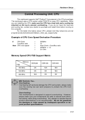
... Support Matrix Memory FSB 400 MHz 533 MHz 800 MHz DDR 266 OK OK N/A DDR 333 N/A OK OK DDR 400 N/A N/A OK MSI Reminds You... Overheating Overheating will seriously damage the CPU and system, always make sure the CPU has a heat sink and a cooling fan...overheating. If you are able to support overclocking. Any attempt to operate beyond product specifications. 2-3 Overclocking This motherboard is not recommended. Hardware Setup Central Processing Unit: CPU The mainboard supports Intel® Pentium® 4 processors in the 478 pin package. When you do not guarantee ...
... Support Matrix Memory FSB 400 MHz 533 MHz 800 MHz DDR 266 OK OK N/A DDR 333 N/A OK OK DDR 400 N/A N/A OK MSI Reminds You... Overheating Overheating will seriously damage the CPU and system, always make sure the CPU has a heat sink and a cooling fan...overheating. If you are able to support overclocking. Any attempt to operate beyond product specifications. 2-3 Overclocking This motherboard is not recommended. Hardware Setup Central Processing Unit: CPU The mainboard supports Intel® Pentium® 4 processors in the 478 pin package. When you do not guarantee ...
User Guide
Page 15
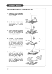
...the power cord before installing the CPU. The CPU can not be completely embedded into the socket and close the lever with your mainboard. 5. Gold arrow Gold arrow Press down firmly into the socket and can only fit in the correct orientation. Pull the lever sideways... Gold arrow 90 degree 4. Look for Socket 478 1. If the CPU is properly and completely embedded into the socket. MS-6788 ATX Mainboard CPU Installation Procedures for the gold arrow. Please note that any violation of the correct installation procedures may cause permanent damages to your fingers...
...the power cord before installing the CPU. The CPU can not be completely embedded into the socket and close the lever with your mainboard. 5. Gold arrow Gold arrow Press down firmly into the socket and can only fit in the correct orientation. Pull the lever sideways... Gold arrow 90 degree 4. Look for Socket 478 1. If the CPU is properly and completely embedded into the socket. MS-6788 ATX Mainboard CPU Installation Procedures for the gold arrow. Please note that any violation of the correct installation procedures may cause permanent damages to your fingers...
User Guide
Page 18
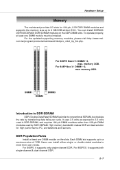
...Users can install DDR266/ DDR333/DDR400 DDR SDRAM modules on the slots. For 865PE Neo2-V: DIMM1~3, max. Hardware Setup Memory The mainboard provides 2/3 slots for high performance PC, workstations and servers. com.tw/program/products/mainboard/mbd/pro_mbd_trp_list.php. For 848P Neo-V: DIMM1~2, max. It uses 2.5 volts... To operate properly, at least one DIMM module must be installed. For the updated supporting memory modules, please visit http://www.msi. memory 3GB. memory 2GB. High memory bandwidth makes DDR an ideal solution for 184-pin, 2.5V DDR DIMM modules and supports...
...Users can install DDR266/ DDR333/DDR400 DDR SDRAM modules on the slots. For 865PE Neo2-V: DIMM1~3, max. Hardware Setup Memory The mainboard provides 2/3 slots for high performance PC, workstations and servers. com.tw/program/products/mainboard/mbd/pro_mbd_trp_list.php. For 848P Neo-V: DIMM1~2, max. It uses 2.5 volts... To operate properly, at least one DIMM module must be installed. For the updated supporting memory modules, please visit http://www.msi. memory 3GB. memory 2GB. High memory bandwidth makes DDR an ideal solution for 184-pin, 2.5V DDR DIMM modules and supports...
User Guide
Page 19
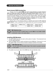
MS-6788 ATX Mainboard Dual-channel DDR Introduction Please note that each side of different type...install memory modules of the DIMM slot will only fit in the right orientation. 2. Dual-channel DDR for 865PE Neo2-V. Insert the DIMM memory module vertically into the DIMM slot. Inserting your memory modules in the memory slot ... A) DIMM3 (Ch B) System Density 128MB~1GB 128MB~1GB 256MB~2GB MSI Reminds You... Other combination not listed below ). Then push it in the socket. Volt Notch 2-8 MSI Reminds You... The DDR DIMM has only one notch on the memory module...
MS-6788 ATX Mainboard Dual-channel DDR Introduction Please note that each side of different type...install memory modules of the DIMM slot will only fit in the right orientation. 2. Dual-channel DDR for 865PE Neo2-V. Insert the DIMM memory module vertically into the DIMM slot. Inserting your memory modules in the memory slot ... A) DIMM3 (Ch B) System Density 128MB~1GB 128MB~1GB 256MB~2GB MSI Reminds You... Other combination not listed below ). Then push it in the socket. Volt Notch 2-8 MSI Reminds You... The DDR DIMM has only one notch on the memory module...

User Guide
Page 20
... 14 5 GND 15 6 5V 16 7 GND 17 8 PW_OK 18 9 5V_SB 19 10 12V 20 SIGNAL 3.3V -12V GND PS_ON GND GND GND -5V 5V 5V ATX 12V Power Connector: JPW1 This 12V power connector is highly recommended for the power system. Power supply of the power supply is inserted in the... proper orientation and the pins are installed properly to the CPU. 3 4 1 2 JPW1 JPW1 Pin Definition PIN SIGNAL 1 GND 2 GND 3 12V 4 12V MSI Reminds You... Hardware Setup Power Supply The mainboard supports ATX power supply for system stability. 2-9
... 14 5 GND 15 6 5V 16 7 GND 17 8 PW_OK 18 9 5V_SB 19 10 12V 20 SIGNAL 3.3V -12V GND PS_ON GND GND GND -5V 5V 5V ATX 12V Power Connector: JPW1 This 12V power connector is highly recommended for the power system. Power supply of the power supply is inserted in the... proper orientation and the pins are installed properly to the CPU. 3 4 1 2 JPW1 JPW1 Pin Definition PIN SIGNAL 1 GND 2 GND 3 12V 4 12V MSI Reminds You... Hardware Setup Power Supply The mainboard supports ATX power supply for system stability. 2-9
User Guide
Page 21
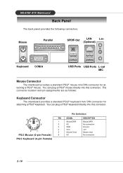
MS-6788 ATX Mainboard Back Panel The back panel provides the following connectors: Mouse Parallel SPDIF-Out LAN (Optional) L-in Keyboard COM A USB Ports USB Ports L-out MIC Mouse Connector The mainboard provides a standard PS/2® mouse mini DIN connector for attaching a PS/2® keyboard. You ... connection Ground +5V Mouse clock No connection 2-10 The connector location and pin assignments are as follows: Keyboard Connector The mainboard provides a standard PS/2® keyboard mini DIN connector for attaching a PS/2® mouse. You can plug a PS/2® mouse directly...
MS-6788 ATX Mainboard Back Panel The back panel provides the following connectors: Mouse Parallel SPDIF-Out LAN (Optional) L-in Keyboard COM A USB Ports USB Ports L-out MIC Mouse Connector The mainboard provides a standard PS/2® mouse mini DIN connector for attaching a PS/2® keyboard. You ... connection Ground +5V Mouse clock No connection 2-10 The connector location and pin assignments are as follows: Keyboard Connector The mainboard provides a standard PS/2® keyboard mini DIN connector for attaching a PS/2® mouse. You can plug a PS/2® mouse directly...

User Guide
Page 22
... send/receive 16 bytes FIFOs. SPDIF-out port 2-11 You can attach a serial mouse or other USBcompatible devices. Hardware Setup Serial Port Connector: COM A The mainboard offers one 9-pin male DIN connector as keyboard, mouse or other serial devices directly to the connectors. 1 2 3 4 5 PIN 1 2 3 4 6... Out or Transmit Data Data Terminal Ready) Ground Data Set Ready Request To Send Clear To Send Ring Indicate USB Connectors The mainboard provides a UHCI (Universal Host Controller Interface) Universal Serial Bus root for digital audio transmission. You can plug the USB device directly...
... send/receive 16 bytes FIFOs. SPDIF-out port 2-11 You can attach a serial mouse or other USBcompatible devices. Hardware Setup Serial Port Connector: COM A The mainboard offers one 9-pin male DIN connector as keyboard, mouse or other serial devices directly to the connectors. 1 2 3 4 5 PIN 1 2 3 4 6... Out or Transmit Data Data Terminal Ready) Ground Data Set Ready Request To Send Clear To Send Ring Indicate USB Connectors The mainboard provides a UHCI (Universal Host Controller Interface) Universal Serial Bus root for digital audio transmission. You can plug the USB device directly...
User Guide
Page 23
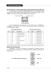
Giga-bit LAN enables data to Local Area Network (LAN). MS-6788 ATX Mainboard RJ-45 LAN Jack: 10/100 LAN (8100C) /Giga-bit LAN (8110S) (Optional) The mainboard provides two standard RJ-45 jacks for connection to be transferred at 1000, 100 or 10Mbps. Note that Pin 1/2, 3/6, 4/5, 7/8 must work in pairs. Please refer...
Giga-bit LAN enables data to Local Area Network (LAN). MS-6788 ATX Mainboard RJ-45 LAN Jack: 10/100 LAN (8100C) /Giga-bit LAN (8110S) (Optional) The mainboard provides two standard RJ-45 jacks for connection to be transferred at 1000, 100 or 10Mbps. Note that Pin 1/2, 3/6, 4/5, 7/8 must work in pairs. Please refer...

User Guide
Page 24
... GND Ground 21 GND Ground 22 GND Ground 23 GND Ground 24 GND Ground 25 GND Ground 2-13 Hardware Setup Parallel Port Connector: LPT1 The mainboard provides a 25-pin female centronic connector as LPT.
... GND Ground 21 GND Ground 22 GND Ground 23 GND Ground 24 GND Ground 25 GND Ground 2-13 Hardware Setup Parallel Port Connector: LPT1 The mainboard provides a 25-pin female centronic connector as LPT.
User Guide
Page 25
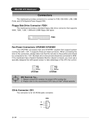
... Always consult the vendors for CD-ROM audio connector. CD1 R GND L 2-14 MS-6788 ATX Mainboard Connectors The mainboard provides connectors to connect to the recommend CPU fans at Intel® official website. Floppy Disk Drive Connector: FDD1... The mainboard provides a standard floppy disk drive connector that the red wire is the positive and should be... and 2.88M floppy disk types. GND +12V Sensor CPUFAN1 GND +12V Sensor SYSFAN1 MSI Reminds You... 1. When connecting the wire to GND.
... Always consult the vendors for CD-ROM audio connector. CD1 R GND L 2-14 MS-6788 ATX Mainboard Connectors The mainboard provides connectors to connect to the recommend CPU fans at Intel® official website. Floppy Disk Drive Connector: FDD1... The mainboard provides a standard floppy disk drive connector that the red wire is the positive and should be... and 2.88M floppy disk types. GND +12V Sensor CPUFAN1 GND +12V Sensor SYSFAN1 MSI Reminds You... 1. When connecting the wire to GND.
User Guide
Page 26
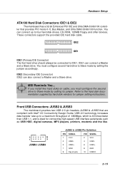
... hard disk drives, CD-ROM, 120MB Floppy and other devices. These connectors support the provided IDE hard disk cable. MSI Reminds You... Front USB Connectors: JUSB2 & JUSB3 The mainboard provides two USB 2.0 pin headers JUSB2 & JUSB3 that provides PIO mode 0~5, Bus Master, and Ultra DMA 33/66... technology increases data transfer rate up to Slave mode by setting the jumper accordingly. Hardware Setup ATA100 Hard Disk Connectors: IDE1 & IDE2 The mainboard has a 32-bit Enhanced PCI IDE and Ultra DMA 33/66/100 controller that are compliant with Intel® I/O Connectivity Design Guide. IDE1...
... hard disk drives, CD-ROM, 120MB Floppy and other devices. These connectors support the provided IDE hard disk cable. MSI Reminds You... Front USB Connectors: JUSB2 & JUSB3 The mainboard provides two USB 2.0 pin headers JUSB2 & JUSB3 that provides PIO mode 0~5, Bus Master, and Ultra DMA 33/66... technology increases data transfer rate up to Slave mode by setting the jumper accordingly. Hardware Setup ATA100 Hard Disk Connectors: IDE1 & IDE2 The mainboard has a 32-bit Enhanced PCI IDE and Ultra DMA 33/66/100 controller that are compliant with Intel® I/O Connectivity Design Guide. IDE1...
User Guide
Page 27
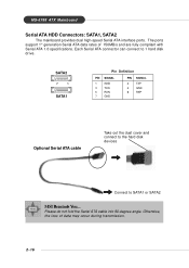
... ATA cable Take out the dust cover and connect to the hard disk devices Connect to 1 hard disk drive. MS-6788 ATX Mainboard Serial ATA HDD Connectors: SATA1, SATA2 The mainboard provides dual high-speed Serial ATA interface ports. The ports support 1st generation Serial ATA data rates of data may occur during...
... ATA cable Take out the dust cover and connect to the hard disk devices Connect to 1 hard disk drive. MS-6788 ATX Mainboard Serial ATA HDD Connectors: SATA1, SATA2 The mainboard provides dual high-speed Serial ATA interface ports. The ports support 1st generation Serial ATA data rates of data may occur during...
User Guide
Page 29
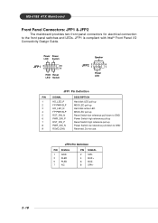
...-up Reset Switch high reference pull-up Power Switch low reference pull-down to the front panel switches and LEDs. MS-6788 ATX Mainboard Front Panel Connectors: JFP1 & JFP2 The mainboard provides two front panel connectors for electrical connection to GND Reserved. JFP1 is compliant with Intel® Front Panel I/O Connectivity Design Guide...
...-up Reset Switch high reference pull-up Power Switch low reference pull-down to the front panel switches and LEDs. MS-6788 ATX Mainboard Front Panel Connectors: JFP1 & JFP2 The mainboard provides two front panel connectors for electrical connection to GND Reserved. JFP1 is compliant with Intel® Front Panel I/O Connectivity Design Guide...


