User Guide
Page 9
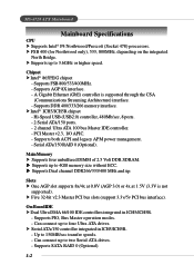
... to 3.6GHz or higher speed. Chipset h Intel® 865PE/G chipset - h Intel® ICH5/ICH5R chipset - Serial ATA/150 RAID 0 (Optional). Supports both ACPI and legacy APM power management. - Slots h One AGP slot supports 8x/4x at 0.8V (AGP 3.0) or 4x at 1.... ATA 100 bus Master IDE controller. - MS-6728 ATX Mainboard Mainboard Specifications CPU h Supports Intel® P4 Northwood/Prescott (Socket 478) processors. h Supports up to 150MB/sec transfer speeds. - A Gigabit Ethernet (GbE) controller is not supported). h Supports up to 4GB memory size without ECC. h Five...
... to 3.6GHz or higher speed. Chipset h Intel® 865PE/G chipset - h Intel® ICH5/ICH5R chipset - Serial ATA/150 RAID 0 (Optional). Supports both ACPI and legacy APM power management. - Slots h One AGP slot supports 8x/4x at 0.8V (AGP 3.0) or 4x at 1.... ATA 100 bus Master IDE controller. - MS-6728 ATX Mainboard Mainboard Specifications CPU h Supports Intel® P4 Northwood/Prescott (Socket 478) processors. h Supports up to 150MB/sec transfer speeds. - A Gigabit Ethernet (GbE) controller is not supported). h Supports up to 4GB memory size without ECC. h Five...

User Guide
Page 10
... port - 1 RJ45 LAN jack (Optional) - 3 IEEE 1394 pinheaders (Optional) Audio h 6 channels software audio codec C-Media 9739A. - Dimension h ATX Form Factor: 30.5 cm (L) x 24.4 cm (W). On-Board Peripherals h On-Board Peripherals include: - 1 floppy port supports 2 FDDs with 360K, 720K, 1.2M, 1.44M and 2.88Mbytes - 1 serial port COM1, 1 VGA port (for Intel® 82547EI). - LAN...
... port - 1 RJ45 LAN jack (Optional) - 3 IEEE 1394 pinheaders (Optional) Audio h 6 channels software audio codec C-Media 9739A. - Dimension h ATX Form Factor: 30.5 cm (L) x 24.4 cm (W). On-Board Peripherals h On-Board Peripherals include: - 1 floppy port supports 2 FDDs with 360K, 720K, 1.2M, 1.44M and 2.88Mbytes - 1 serial port COM1, 1 VGA port (for Intel® 82547EI). - LAN...
User Guide
Page 15
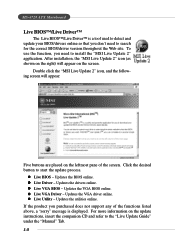
...listed above, a "sorry" message is a tool used to detect and update your BIOS/drivers online so that you don't need to install the "MSI Live Update 2" application. Updates the VGA BIOS online. Updates the utilities online. z Live BIOS - z Live VGA BIOS - If the product you purchased... does not support any of the screen. MS-6728 ATX Mainboard Live BIOS™/Live Driver™ The Live BIOS™/Live Driver™ is displayed. For more information on the screen...
...listed above, a "sorry" message is a tool used to detect and update your BIOS/drivers online so that you don't need to install the "MSI Live Update 2" application. Updates the VGA BIOS online. Updates the utilities online. z Live BIOS - z Live VGA BIOS - If the product you purchased... does not support any of the screen. MS-6728 ATX Mainboard Live BIOS™/Live Driver™ The Live BIOS™/Live Driver™ is displayed. For more information on the screen...
User Guide
Page 17
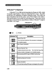
MS-6728 ATX Mainboard D-Bracket™ 2 (Optional) D-Bracket™ 2 is very useful for fast booting. These users can detect all problems that fail the system, such as VGA, ... the system. The D-LED will hang here if the processor is damaged or not installed properly. Decompressing BIOS image to the screen. 1-10 D-Bracket™ 2 supports both USB 1.1 & 2.0 spec. This will hang if the memory module is damaged or 3 4 not installed properly. The 4 LEDs can use graphic signal display to help...
MS-6728 ATX Mainboard D-Bracket™ 2 (Optional) D-Bracket™ 2 is very useful for fast booting. These users can detect all problems that fail the system, such as VGA, ... the system. The D-LED will hang here if the processor is damaged or not installed properly. Decompressing BIOS image to the screen. 1-10 D-Bracket™ 2 supports both USB 1.1 & 2.0 spec. This will hang if the memory module is damaged or 3 4 not installed properly. The 4 LEDs can use graphic signal display to help...
User Guide
Page 24
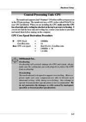
...do not guarantee the damages or risks caused by inadequate operation or beyond product specifications is designed to prevent overheating. Overclocking This motherboard is not recommended. We do not find the heat sink and cooling fan, contact your components are installing the CPU, ...Bus ratio = 16 then CPU core speed = Host Clock x Core/Bus ratio = 100MHz x 16 = 1.6 GHz MSI Reminds You... Hardware Setup Central Processing Unit: CPU The mainboard supports Intel® Pentium® 4 Northwood/Prescott processor in the 478 pin package. The mainboard uses a CPU socket called ...
...do not guarantee the damages or risks caused by inadequate operation or beyond product specifications is designed to prevent overheating. Overclocking This motherboard is not recommended. We do not find the heat sink and cooling fan, contact your components are installing the CPU, ...Bus ratio = 16 then CPU core speed = Host Clock x Core/Bus ratio = 100MHz x 16 = 1.6 GHz MSI Reminds You... Hardware Setup Central Processing Unit: CPU The mainboard supports Intel® Pentium® 4 Northwood/Prescott processor in the 478 pin package. The mainboard uses a CPU socket called ...
User Guide
Page 28
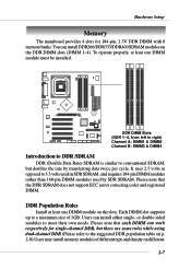
To operate properly, at least one DIMM module must be installed. Each DIMM slot supports up to meet their own needs. You can install DDR266/DDR333/DDR400 SDRAM modules on different- 2-7 BATT + DDR DIMM Slots (DDR 1~4, from left to right) ... double-sided modules to a maximum size of different type and density on the DDR DIMM slots (DIMM 1~4). Please note that the DDR SDRAM does not support ECC (error correcting code) and registered DIMM. DDR Population Rules Install at least one DIMM module on the slots. Please note that each DIMM can...
To operate properly, at least one DIMM module must be installed. Each DIMM slot supports up to meet their own needs. You can install DDR266/DDR333/DDR400 SDRAM modules on different- 2-7 BATT + DDR DIMM Slots (DDR 1~4, from left to right) ... double-sided modules to a maximum size of different type and density on the DDR DIMM slots (DIMM 1~4). Please note that the DDR SDRAM does not support ECC (error correcting code) and registered DIMM. DDR Population Rules Install at least one DIMM module on the slots. Please note that each DIMM can...
User Guide
Page 30
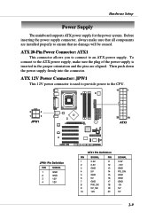
... 2-9 Then push down the power supply firmly into the connector. Hardware Setup Power Supply The mainboard supports ATX power supply for the power system. To connect to ensure that all components are aligned. ATX 12V Power Connector: JPW1 This 12V power connector is inserted in the proper orientation and the pins ...are installed properly to the ATX power supply, make sure that no damage will be caused. Before inserting the power supply connector, always make sure the plug of the ...
... 2-9 Then push down the power supply firmly into the connector. Hardware Setup Power Supply The mainboard supports ATX power supply for the power system. To connect to ensure that all components are aligned. ATX 12V Power Connector: JPW1 This 12V power connector is inserted in the proper orientation and the pins ...are installed properly to the ATX power supply, make sure that no damage will be caused. Before inserting the power supply connector, always make sure the plug of the ...
User Guide
Page 35
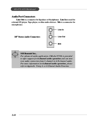
... on 6-channel audio operation, please refer to 4-/6-channel audio. MS-6728 ATX Mainboard Audio Port Connectors Line Out is a connector for microphones. Line In 1/8" Stereo Audio Connectors Line Out MIC MSI Reminds You... or 6-Channel Audio Function. 2-14 Mic is a connector ...for Speakers or Headphones. For advanced audio application, CMedia 9739A is used for 6-channel audio operation and can turn rear audio connectors from 2-channel to Appendix. Using 4- Line In is provided to offer support...
... on 6-channel audio operation, please refer to 4-/6-channel audio. MS-6728 ATX Mainboard Audio Port Connectors Line Out is a connector for microphones. Line In 1/8" Stereo Audio Connectors Line Out MIC MSI Reminds You... or 6-Channel Audio Function. 2-14 Mic is a connector ...for Speakers or Headphones. For advanced audio application, CMedia 9739A is used for 6-channel audio operation and can turn rear audio connectors from 2-channel to Appendix. Using 4- Line In is provided to offer support...
User Guide
Page 36
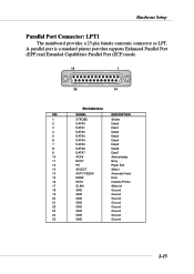
A parallel port is a standard printer port that supports Enhanced Parallel Port (EPP) and Extended Capabilities Parallel Port (ECP) mode. 13 1 25 14 Pin Definition PIN SIGNAL DESCRIPTION 1 STROBE Strobe 2 DATA0 Data0 3 DATA1 Data1 4 ...
A parallel port is a standard printer port that supports Enhanced Parallel Port (EPP) and Extended Capabilities Parallel Port (ECP) mode. 13 1 25 14 Pin Definition PIN SIGNAL DESCRIPTION 1 STROBE Strobe 2 DATA0 Data0 3 DATA1 Data1 4 ...
User Guide
Page 37
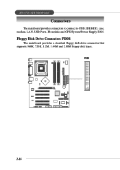
FDD1 B ATT + 2-16 Floppy Disk Drive Connector: FDD1 The mainboard provides a standard floppy disk drive connector that supports 360K, 720K, 1.2M, 1.44M and 2.88M floppy disk types. MS-6728 ATX Mainboard Connectors The mainboard provides connectors to connect to FDD, IDE HDD, case, modem, LAN, USB Ports, IR module and CPU/System/Power Supply FAN.
FDD1 B ATT + 2-16 Floppy Disk Drive Connector: FDD1 The mainboard provides a standard floppy disk drive connector that supports 360K, 720K, 1.2M, 1.44M and 2.88M floppy disk types. MS-6728 ATX Mainboard Connectors The mainboard provides connectors to connect to FDD, IDE HDD, case, modem, LAN, USB Ports, IR module and CPU/System/Power Supply FAN.
User Guide
Page 38
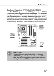
... control the CPU fan speed according to GND. GND +12V SENSOR CPUFAN1 GND +12V Sensor NBFAN1 B ATT + GND +12V NC SFAN1 MSI Reminds You... 1. It supports three-pin head connector. You can install Core Center utility that the red wire is the positive and should be connected to the +12V..., the black wire is Ground and should be connected to the actual CPU temperature. 2-17 CPUFAN1 supports the fan control. When connecting the wire to the connectors, always take advantage of the CPU fan control. If the mainboard has a System Hardware...
... control the CPU fan speed according to GND. GND +12V SENSOR CPUFAN1 GND +12V Sensor NBFAN1 B ATT + GND +12V NC SFAN1 MSI Reminds You... 1. It supports three-pin head connector. You can install Core Center utility that the red wire is the positive and should be connected to the +12V..., the black wire is Ground and should be connected to the actual CPU temperature. 2-17 CPUFAN1 supports the fan control. When connecting the wire to the connectors, always take advantage of the CPU fan control. If the mainboard has a System Hardware...
User Guide
Page 40
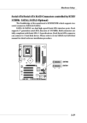
... generation serial ATA data rates of this mainboard is ICH5/ICH5R which supports two serial connectors SATA1& SATA2. SATA1 & SATA2 are fully compliant with Serial ATA 1.0 specifications. Each Serial ATA connector can connect to Serial ATA/Serial ATA ...
... generation serial ATA data rates of this mainboard is ICH5/ICH5R which supports two serial connectors SATA1& SATA2. SATA1 & SATA2 are fully compliant with Serial ATA 1.0 specifications. Each Serial ATA connector can connect to Serial ATA/Serial ATA ...
User Guide
Page 41
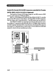
... Serial ATA connector can connect up to 1 hard disk device. MS-6728 ATX Mainboard Serial ATA /Serial ATA RAID Connectors controlled by Promise 20378: IDE3, SATA3 & SATA4 (Optional) The brand new Promise 20378 chipset supports one IDE slave. Please refer to Serial ATA/Serial ATA Raid manual for... detail software installation procedure. 2-20 B AT T + IDE3 7 1 SATA4 SATA3 Each supports 1st generation serial ATA data rates of 150 MB/s. And STAT3 & SATA4 are fully compliant with Serial ATA 1.0 specifications. IDE3 is a 32-...
... Serial ATA connector can connect up to 1 hard disk device. MS-6728 ATX Mainboard Serial ATA /Serial ATA RAID Connectors controlled by Promise 20378: IDE3, SATA3 & SATA4 (Optional) The brand new Promise 20378 chipset supports one IDE slave. Please refer to Serial ATA/Serial ATA Raid manual for... detail software installation procedure. 2-20 B AT T + IDE3 7 1 SATA4 SATA3 Each supports 1st generation serial ATA data rates of 150 MB/s. And STAT3 & SATA4 are fully compliant with Serial ATA 1.0 specifications. IDE3 is a 32-...
User Guide
Page 43
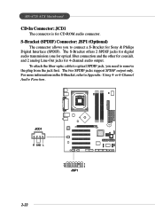
The two SPDIF jacks support SPDIF output only. To attach the fiber-optic cable to optical SPDIF jack, you to connect a S-Bracket for Sony & Philips Digital Interface (SPDIF). B ATT + JCD1 R GND L 11 1 12 2 JSP1 2-22 MS-6728 ATX Mainboard CD-In Connector: JCD1 The connector is for 4-channel audio output. or 6-Channel Audio...
The two SPDIF jacks support SPDIF output only. To attach the fiber-optic cable to optical SPDIF jack, you to connect a S-Bracket for Sony & Philips Digital Interface (SPDIF). B ATT + JCD1 R GND L 11 1 12 2 JSP1 2-22 MS-6728 ATX Mainboard CD-In Connector: JCD1 The connector is for 4-channel audio output. or 6-Channel Audio...
User Guide
Page 50
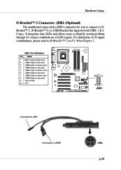
... system problem through 16 various combinations of 16 signal combinations, please refer to D-Bracket™ 2 at P.1-10 in Chapter 1. D-Bracket™ 2 is a USB Bracket that supports both USB1.1 & 2. 0 spec. Hardware Setup D-Bracket™ 2 Connector: JDB1 (Optional) The mainboard comes with a JDB1 connector for red color) 9 Key (no pin) 10 NC BATT...
... system problem through 16 various combinations of 16 signal combinations, please refer to D-Bracket™ 2 at P.1-10 in Chapter 1. D-Bracket™ 2 is a USB Bracket that supports both USB1.1 & 2. 0 spec. Hardware Setup D-Bracket™ 2 Connector: JDB1 (Optional) The mainboard comes with a JDB1 connector for red color) 9 Key (no pin) 10 NC BATT...
User Guide
Page 54
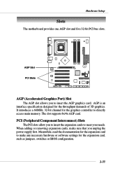
The slot supports 8x/4x AGP card. Hardware Setup Slots The motherboard provides one AGP slot and five 32-bit PCI bus slots. B AT T AGP Slot + PCI Slots AGP (Accelerated Graphics Port) Slot The AGP slot allows ...
The slot supports 8x/4x AGP card. Hardware Setup Slots The motherboard provides one AGP slot and five 32-bit PCI bus slots. B AT T AGP Slot + PCI Slots AGP (Accelerated Graphics Port) Slot The AGP slot allows ...
User Guide
Page 59
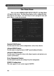
...time, date etc. Use arrow keys to move among the items and press to change the values in the chipset registers and optimize your system supports PnP/PCI. 3-4 Standard CMOS Features Use this menu to setup the items of AMI® special enhanced features. PNP/PCI Configurations This entry ...appears if your system's performance. Advanced BIOS Features Use this menu to enter the sub-menu. MS-6728 ATX Mainboard The Main Menu Once you enter AMIBIOS NEW SETUP UTILITY, the Main Menu will appear on the screen. The Main Menu displays twelve ...
...time, date etc. Use arrow keys to move among the items and press to change the values in the chipset registers and optimize your system supports PnP/PCI. 3-4 Standard CMOS Features Use this menu to setup the items of AMI® special enhanced features. PNP/PCI Configurations This entry ...appears if your system's performance. Advanced BIOS Features Use this menu to enter the sub-menu. MS-6728 ATX Mainboard The Main Menu Once you enter AMIBIOS NEW SETUP UTILITY, the Main Menu will appear on the screen. The Main Menu displays twelve ...
User Guide
Page 65
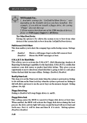
This gives you to All Device. BootUp Num-Lock This item is to set USB Legacy Support to show up. 2. Floppy Drive Swap Setting to move back and forth once. Setting options: Disabled, Enabled. 3-10 Full Screen LOGO Show This item enables .../2nd/3rd Boot Device" vary depending on the numeric keypad. Available settings for the hard disks. Disabled Shows the POST messages at boot. MS-6728 ATX Mainboard MSI Reminds You... 1. If you to use the arrow keys on the bootable devices you did not install a floppy drive, the setting "Floppy" does not...
This gives you to All Device. BootUp Num-Lock This item is to set USB Legacy Support to show up. 2. Floppy Drive Swap Setting to move back and forth once. Setting options: Disabled, Enabled. 3-10 Full Screen LOGO Show This item enables .../2nd/3rd Boot Device" vary depending on the numeric keypad. Available settings for the hard disks. Disabled Shows the POST messages at boot. MS-6728 ATX Mainboard MSI Reminds You... 1. If you to use the arrow keys on the bootable devices you did not install a floppy drive, the setting "Floppy" does not...
User Guide
Page 66
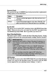
... you cannot run the OS/2® operating system with DRAM larger than 64MB. When you choose No, you to select the MPS version supported by your computer system requires ALL of the following platform Components: *CPU: An Intel® Pentium® 4 Processor with DRAM larger ... Setting to run Setup. Setting options are described below. MSI Reminds You... You need to run the OS/2® operating system with HT Technology; *Chipset: An Intel® Chipset that supports HT Technology; *BIOS: A BIOS that supports HT Technology and has it is used for your operating system...
... you cannot run the OS/2® operating system with DRAM larger than 64MB. When you choose No, you to select the MPS version supported by your computer system requires ALL of the following platform Components: *CPU: An Intel® Pentium® 4 Processor with DRAM larger ... Setting to run Setup. Setting options are described below. MSI Reminds You... You need to run the OS/2® operating system with HT Technology; *Chipset: An Intel® Chipset that supports HT Technology; *BIOS: A BIOS that supports HT Technology and has it is used for your operating system...
User Guide
Page 71
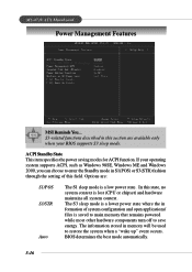
Options are available only when your operating system supports ACPI, such as Windows 98SE, Windows ME and Windows 2000, you can choose to restore the system when a "... of this state, no system context is lost (CPU or chipset) and hardware maintains all system context. MS-6728 ATX Mainboard Power Management Features MSI Reminds You... S3-related functions described in S1(POS) or S3(STR) fashion through the setting of system configuration and... energy. ACPI Standby State This item specifies the power saving modes for ACPI function. If your BIOS supports S3 sleep mode. In this field.
Options are available only when your operating system supports ACPI, such as Windows 98SE, Windows ME and Windows 2000, you can choose to restore the system when a "... of this state, no system context is lost (CPU or chipset) and hardware maintains all system context. MS-6728 ATX Mainboard Power Management Features MSI Reminds You... S3-related functions described in S1(POS) or S3(STR) fashion through the setting of system configuration and... energy. ACPI Standby State This item specifies the power saving modes for ACPI function. If your BIOS supports S3 sleep mode. In this field.


