
User Guide
Page 10
..., 1.44M and 2.88Mbytes - 1 serial port COM1, 1 VGA port (for Intel® 82547EI). - LAN (Optional) h Intel® 82547EI (CSA interface) /Intel® 82562EZ Dual layout. - Dimension h ATX Form Factor: 30.5 cm (L) x 24.4 cm (W). Getting Started Promise 20378 On-Board (Optional) h Supports Ultra ATA, Serial ATA, Ultra ATA RAID 0 or 1 , Serial ATA RAID... "Plug & Play" BIOS which records your mainboard specifications. On-Board Peripherals h On-Board Peripherals include: - 1 floppy port supports 2 FDDs with PCI 2.2. - Compliance with AC97 v2.2 Spec. -
..., 1.44M and 2.88Mbytes - 1 serial port COM1, 1 VGA port (for Intel® 82547EI). - LAN (Optional) h Intel® 82547EI (CSA interface) /Intel® 82562EZ Dual layout. - Dimension h ATX Form Factor: 30.5 cm (L) x 24.4 cm (W). Getting Started Promise 20378 On-Board (Optional) h Supports Ultra ATA, Serial ATA, Ultra ATA RAID 0 or 1 , Serial ATA RAID... "Plug & Play" BIOS which records your mainboard specifications. On-Board Peripherals h On-Board Peripherals include: - 1 floppy port supports 2 FDDs with PCI 2.2. - Compliance with AC97 v2.2 Spec. -
User Guide
Page 17
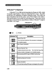
MS-6728 ATX Mainboard D-Bracket™ 2 (Optional) D-Bracket™ 2 is a USB bracket integrating four Diagnostic LEDs, which use the feature to detect if there are any problems or ... useful for fast booting. Decompressing BIOS image to the screen. 1-10 This special feature is damaged or 3 4 not installed properly. D-Bracket™ 2 supports both USB 1.1 & 2.0 spec. Testing VGA BIOS - This will hang if the memory module is damaged or not installed properly. The 4 LEDs can use graphic signal display to debug...
MS-6728 ATX Mainboard D-Bracket™ 2 (Optional) D-Bracket™ 2 is a USB bracket integrating four Diagnostic LEDs, which use the feature to detect if there are any problems or ... useful for fast booting. Decompressing BIOS image to the screen. 1-10 This special feature is damaged or 3 4 not installed properly. D-Bracket™ 2 supports both USB 1.1 & 2.0 spec. Testing VGA BIOS - This will hang if the memory module is damaged or not installed properly. The 4 LEDs can use graphic signal display to debug...
User Guide
Page 21
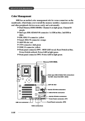
.... Memory DDR DIMMs Intel spec IDE ATA66/100 connectors: 1st IDE: blue/2nd IDE: white B ATT + AGP 8X Slot USB 2.0 connector 1394 connectors Serial ATA150 connectors IDE ATA133 connector Serial ATA150 connectors Front Panel connector JFP1 Front Panel connector JFP2 1-14 MS-6728 ATX Mainboard Color Management MSI has an unified color management...
.... Memory DDR DIMMs Intel spec IDE ATA66/100 connectors: 1st IDE: blue/2nd IDE: white B ATT + AGP 8X Slot USB 2.0 connector 1394 connectors Serial ATA150 connectors IDE ATA133 connector Serial ATA150 connectors Front Panel connector JFP1 Front Panel connector JFP2 1-14 MS-6728 ATX Mainboard Color Management MSI has an unified color management...
User Guide
Page 49
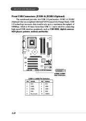
... Definition PIN SIGNAL PIN SIGNAL 1 VCC 2 VCC 3 USB0- 4 USB1- 5 USB0+ 6 USB1+ 7 GND 8 GND 9 Key (no pin) 10 USBOC 2 10 1 9 JUSB2, JUSB1 (USB 2.0/Intel spec) 2-28 MS-6728 ATX Mainboard Front USB Connectors: JUSB1 & JUSB2 (Optional) The mainboard provides two USB 2.0 pin headers JUSB1 & JUSB2 (Optional) that are compliant with Intel® I/O Connectivity...
... Definition PIN SIGNAL PIN SIGNAL 1 VCC 2 VCC 3 USB0- 4 USB1- 5 USB0+ 6 USB1+ 7 GND 8 GND 9 Key (no pin) 10 USBOC 2 10 1 9 JUSB2, JUSB1 (USB 2.0/Intel spec) 2-28 MS-6728 ATX Mainboard Front USB Connectors: JUSB1 & JUSB2 (Optional) The mainboard provides two USB 2.0 pin headers JUSB1 & JUSB2 (Optional) that are compliant with Intel® I/O Connectivity...
User Guide
Page 50
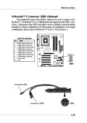
... identify system problem through 16 various combinations of 16 signal combinations, please refer to DBracket™ 2. D-Bracket™ 2 is a USB Bracket that supports both USB1.1 & 2. 0 spec. For definitions of LED signals.
... identify system problem through 16 various combinations of 16 signal combinations, please refer to DBracket™ 2. D-Bracket™ 2 is a USB Bracket that supports both USB1.1 & 2. 0 spec. For definitions of LED signals.
