User Guide
Page 2
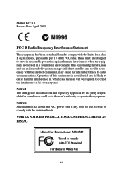
... to comply with the instruction manual, may cause harmful interference to radio communications. VOIR LA NOTICE D'INSTALLATION AVANT DE RACCORDER AU RESEAU. Micro-Star International MS-6728 Tested to comply with the limits for compliance could void the user's authority to operate the equipment. Manual Rev: 1.1 Release Date: April 2003 FCC...
... to comply with the instruction manual, may cause harmful interference to radio communications. VOIR LA NOTICE D'INSTALLATION AVANT DE RACCORDER AU RESEAU. Micro-Star International MS-6728 Tested to comply with the limits for compliance could void the user's authority to operate the equipment. Manual Rev: 1.1 Release Date: April 2003 FCC...
User Guide
Page 8
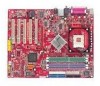
Getting Started Getting Started Thank you for optimal system efficiency. Designed to fit the advanced Intel® Pentium® 4 processors in 478 pin package, the 865 PE/G Neo2 delivers a high performance and professional desktop platform solution. 1-1 The 865 PE/G Neo2 is based on Intel® 865PE/ G & ICH5 chipsets for choosing the 865 PE/G Neo2 (MS-6728) v1. X ATX mainboard. Getting Started Chapter 1.
Getting Started Getting Started Thank you for optimal system efficiency. Designed to fit the advanced Intel® Pentium® 4 processors in 478 pin package, the 865 PE/G Neo2 delivers a high performance and professional desktop platform solution. 1-1 The 865 PE/G Neo2 is based on Intel® 865PE/ G & ICH5 chipsets for choosing the 865 PE/G Neo2 (MS-6728) v1. X ATX mainboard. Getting Started Chapter 1.
User Guide
Page 9
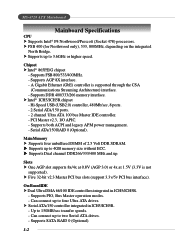
Chipset h Intel® 865PE/G chipset - Serial ATA/150 RAID 0 (Optional). h Supports up to 3.6GHz or higher speed. Slots h One AGP slot supports 8x/4x at 0.8V (AGP 3.0) or 4x ... IDE h Dual Ultra DMA 66/100 IDE controllers integrated in ICH5/ICH5R. - Supports FSB 800/533/400MHz. - Can connect up to 150MB/sec transfer speeds. - MS-6728 ATX Mainboard Mainboard Specifications CPU h Supports Intel® P4 Northwood/Prescott (Socket 478) processors. A Gigabit Ethernet (GbE) controller is not supported). Main Memory h Supports four...
Chipset h Intel® 865PE/G chipset - Serial ATA/150 RAID 0 (Optional). h Supports up to 3.6GHz or higher speed. Slots h One AGP slot supports 8x/4x at 0.8V (AGP 3.0) or 4x ... IDE h Dual Ultra DMA 66/100 IDE controllers integrated in ICH5/ICH5R. - Supports FSB 800/533/400MHz. - Can connect up to 150MB/sec transfer speeds. - MS-6728 ATX Mainboard Mainboard Specifications CPU h Supports Intel® P4 Northwood/Prescott (Socket 478) processors. A Gigabit Ethernet (GbE) controller is not supported). Main Memory h Supports four...
User Guide
Page 11
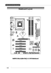
... PCI Slot 4 PCI Slot 5 VIA VT6306 S ATA 4 IDE 3 PROMISE PDC20378 S ATA 3 SFAN1 JA UD 1 JUSB2 (Optional) JUSB1 J1394_1 J1394_2 J1394_3 JFP2 JFP1 JIR1 865PE/G Neo2 (MS-6728) v1.X ATX Mainboard 1-4 MS-6728 ATX Mainboard Mainboard Layout DIMM 1 DIMM 2 DIMM 3 DIMM 4 Top : mouse Bottom: keyboard USB ports Top : Parallel Port Bottom: COM A VGA Port (Optional) CP UFA...
... PCI Slot 4 PCI Slot 5 VIA VT6306 S ATA 4 IDE 3 PROMISE PDC20378 S ATA 3 SFAN1 JA UD 1 JUSB2 (Optional) JUSB1 J1394_1 J1394_2 J1394_3 JFP2 JFP1 JIR1 865PE/G Neo2 (MS-6728) v1.X ATX Mainboard 1-4 MS-6728 ATX Mainboard Mainboard Layout DIMM 1 DIMM 2 DIMM 3 DIMM 4 Top : mouse Bottom: keyboard USB ports Top : Parallel Port Bottom: COM A VGA Port (Optional) CP UFA...
User Guide
Page 13
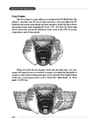
... the right side it shows the current system status including the Vcore, 3.3V, +5V and 12V. If you to send out the warning messages. MS-6728 ATX Mainboard Core Center The Core Center is just like your PC doctor that can find in the CD-ROM disk. When you can detect, view...
... the right side it shows the current system status including the Vcore, 3.3V, +5V and 12V. If you to send out the warning messages. MS-6728 ATX Mainboard Core Center The Core Center is just like your PC doctor that can find in the CD-ROM disk. When you can detect, view...
User Guide
Page 15
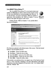
...driver version throughout the Web site. z Live VGA BIOS - Updates the VGA driver online. For more information on the screen. After installation, the "MSI Live Update 2" icon (as shown on the right) will appear: Five buttons are placed on the leftmost pane of the functions listed above, a... will appear on the update instructions, insert the companion CD and refer to install the "MSI Live Update 2" application. Updates the VGA BIOS online. z Live VGA Driver - z Live Utility - MS-6728 ATX Mainboard Live BIOS™/Live Driver™ The Live BIOS™/Live Driver™ is displayed...
...driver version throughout the Web site. z Live VGA BIOS - Updates the VGA driver online. For more information on the screen. After installation, the "MSI Live Update 2" icon (as shown on the right) will appear: Five buttons are placed on the leftmost pane of the functions listed above, a... will appear on the update instructions, insert the companion CD and refer to install the "MSI Live Update 2" application. Updates the VGA BIOS online. z Live VGA Driver - z Live Utility - MS-6728 ATX Mainboard Live BIOS™/Live Driver™ The Live BIOS™/Live Driver™ is displayed...
User Guide
Page 17
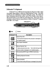
... LEDs provide up to 16 combinations of signals to debug the system. The 4 LEDs can use graphic signal display to help users understand their system. MS-6728 ATX Mainboard D-Bracket™ 2 (Optional) D-Bracket™ 2 is a USB bracket integrating four Diagnostic LEDs, which use the feature to detect if there are any problems...
... LEDs provide up to 16 combinations of signals to debug the system. The 4 LEDs can use graphic signal display to help users understand their system. MS-6728 ATX Mainboard D-Bracket™ 2 (Optional) D-Bracket™ 2 is a USB bracket integrating four Diagnostic LEDs, which use the feature to detect if there are any problems...
User Guide
Page 19
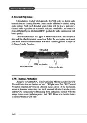
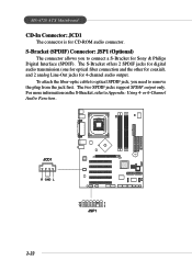
... transmission and 2 analog Line-Out connectors for Intel® Pentium CPU only. 1-12 Please note that this unique feature, users can better protect their CPU. MS-6728 ATX Mainboard S-Bracket (Optional) S-Bracket is for additional 4-channel analog audio output. S-Bracket SPDIF jack (coaxial) SPDIF jack (optical) Analog Line-Out jacks CPU ...drop down and resume normal. With the S-Bracket, your need. This CPU Thermal Protection mechanism works on S-Bracket, refer to prevent the CPU from overheating, MSI has developed a CPU Thermal Protection mechanism for coaxial connection.
... transmission and 2 analog Line-Out connectors for Intel® Pentium CPU only. 1-12 Please note that this unique feature, users can better protect their CPU. MS-6728 ATX Mainboard S-Bracket (Optional) S-Bracket is for additional 4-channel analog audio output. S-Bracket SPDIF jack (coaxial) SPDIF jack (optical) Analog Line-Out jacks CPU ...drop down and resume normal. With the S-Bracket, your need. This CPU Thermal Protection mechanism works on S-Bracket, refer to prevent the CPU from overheating, MSI has developed a CPU Thermal Protection mechanism for coaxial connection.
User Guide
Page 21
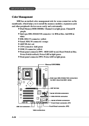
... ATA133 connector Serial ATA150 connectors Front Panel connector JFP1 Front Panel connector JFP2 1-14 h Front panel connector JFP2: Power LED in light green. MS-6728 ATX Mainboard Color Management MSI has an unified color management rule for some connectors on the mainboards, which helps you to install the memory modules, expansion cards and...
... ATA133 connector Serial ATA150 connectors Front Panel connector JFP1 Front Panel connector JFP2 1-14 h Front panel connector JFP2: Power LED in light green. MS-6728 ATX Mainboard Color Management MSI has an unified color management rule for some connectors on the mainboards, which helps you to install the memory modules, expansion cards and...
User Guide
Page 25
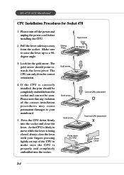
... the socket. The gold arrow should be completely embedded into the socket and close the lever with your mainboard. 5. The CPU can not be seen. MS-6728 ATX Mainboard CPU Installation Procedures for the gold arrow. If the CPU is likely to a 90degree angle. 3. Sliding Plate Open Lever 90 degree Gold arrow...
... the socket. The gold arrow should be completely embedded into the socket and close the lever with your mainboard. 5. The CPU can not be seen. MS-6728 ATX Mainboard CPU Installation Procedures for the gold arrow. If the CPU is likely to a 90degree angle. 3. Sliding Plate Open Lever 90 degree Gold arrow...
User Guide
Page 27
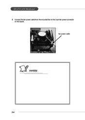
MS-6728 ATX Mainboard 5. Connect the fan power cable from the mounted fan to the 3-pin fan power connector on the board. fan power cable NOTES 2-6
MS-6728 ATX Mainboard 5. Connect the fan power cable from the mounted fan to the 3-pin fan power connector on the board. fan power cable NOTES 2-6
User Guide
Page 29
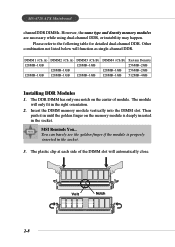
...if the module is deeply inserted in the socket. The module will automatically close. Insert the DIMM memory module vertically into the DIMM slot. MSI Reminds You... The plastic clip at each side of module. The DDR DIMM has only one notch on the memory module is properly inserted ...in the right orientation. 2. MS-6728 ATX Mainboard channelDDR DIMMs. However, the same type and density memory modules are necessary while using dual-channel DDR, or instability may happen. Please ...
...if the module is deeply inserted in the socket. The module will automatically close. Insert the DIMM memory module vertically into the DIMM slot. MSI Reminds You... The plastic clip at each side of module. The DDR DIMM has only one notch on the memory module is properly inserted ...in the right orientation. 2. MS-6728 ATX Mainboard channelDDR DIMMs. However, the same type and density memory modules are necessary while using dual-channel DDR, or instability may happen. Please ...
User Guide
Page 31
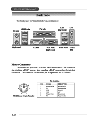
...) Pin Definition PIN SIGNAL 1 Mouse DATA 2 NC 3 GND 4 VCC 5 Mouse Clock 6 NC DESCRIPTION Mouse DATA No connection Ground +5V Mouse clock No connection 2-10 MS-6728 ATX Mainboard Back Panel The back panel provides the following connectors: USB Ports Mouse Parallel LAN L-in (Optional) Keyboard COMA VGA Port (Optional) USB Ports L-out...
...) Pin Definition PIN SIGNAL 1 Mouse DATA 2 NC 3 GND 4 VCC 5 Mouse Clock 6 NC DESCRIPTION Mouse DATA No connection Ground +5V Mouse clock No connection 2-10 MS-6728 ATX Mainboard Back Panel The back panel provides the following connectors: USB Ports Mouse Parallel LAN L-in (Optional) Keyboard COMA VGA Port (Optional) USB Ports L-out...
User Guide
Page 33
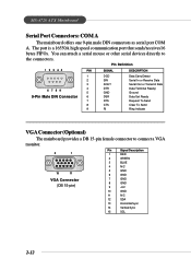
...) Pin Signal Description 1 RED 2 GREEN 3 BLUE 4 N/C 5 GND 6 GND 7 GND 8 GND 9 +5V 10 GND 11 N/C 12 SDA 13 Horizontal Sync 14 Vertical Sync 15 SCL 2-12 MS-6728 ATX Mainboard Serial Port Connectors: COM A The mainboard offers one 9-pin male DIN connectors as serial port COM A. Pin Definition 1 2 3 4 5 PIN SIGNAL DESCRIPTION 1 2 3 4 6 7 8 9 5 9-Pin Male...
...) Pin Signal Description 1 RED 2 GREEN 3 BLUE 4 N/C 5 GND 6 GND 7 GND 8 GND 9 +5V 10 GND 11 N/C 12 SDA 13 Horizontal Sync 14 Vertical Sync 15 SCL 2-12 MS-6728 ATX Mainboard Serial Port Connectors: COM A The mainboard offers one 9-pin male DIN connectors as serial port COM A. Pin Definition 1 2 3 4 5 PIN SIGNAL DESCRIPTION 1 2 3 4 6 7 8 9 5 9-Pin Male...
User Guide
Page 35
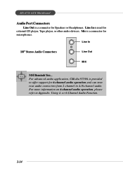
... from 2-channel to Appendix. For more information on 6-channel audio operation, please refer to 4-/6-channel audio. Line In 1/8" Stereo Audio Connectors Line Out MIC MSI Reminds You... MS-6728 ATX Mainboard Audio Port Connectors Line Out is a connector for external CD player, Tape player, or other audio devices. or 6-Channel Audio Function. 2-14...
... from 2-channel to Appendix. For more information on 6-channel audio operation, please refer to 4-/6-channel audio. Line In 1/8" Stereo Audio Connectors Line Out MIC MSI Reminds You... MS-6728 ATX Mainboard Audio Port Connectors Line Out is a connector for external CD player, Tape player, or other audio devices. or 6-Channel Audio Function. 2-14...
User Guide
Page 37
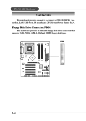
Floppy Disk Drive Connector: FDD1 The mainboard provides a standard floppy disk drive connector that supports 360K, 720K, 1.2M, 1.44M and 2.88M floppy disk types. FDD1 B ATT + 2-16 MS-6728 ATX Mainboard Connectors The mainboard provides connectors to connect to FDD, IDE HDD, case, modem, LAN, USB Ports, IR module and CPU/System/Power Supply FAN.
Floppy Disk Drive Connector: FDD1 The mainboard provides a standard floppy disk drive connector that supports 360K, 720K, 1.2M, 1.44M and 2.88M floppy disk types. FDD1 B ATT + 2-16 MS-6728 ATX Mainboard Connectors The mainboard provides connectors to connect to FDD, IDE HDD, case, modem, LAN, USB Ports, IR module and CPU/System/Power Supply FAN.
User Guide
Page 39
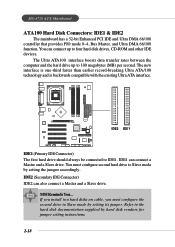
MSI Reminds You... The new interface is one-third faster than earlier record-breaking Ultra ATA/100 technology and is backwards compatible with the existing Ultra ..., you must configure second hard drive to the hard disk documentation supplied by setting its jumper. Refer to Slave mode by setting the jumper accordingly. MS-6728 ATX Mainboard ATA100 Hard Disk Connectors: IDE1 & IDE2 The mainboard has a 32-bit Enhanced PCI IDE and Ultra DMA 66/100 controller that provides PIO...
MSI Reminds You... The new interface is one-third faster than earlier record-breaking Ultra ATA/100 technology and is backwards compatible with the existing Ultra ..., you must configure second hard drive to the hard disk documentation supplied by setting its jumper. Refer to Slave mode by setting the jumper accordingly. MS-6728 ATX Mainboard ATA100 Hard Disk Connectors: IDE1 & IDE2 The mainboard has a 32-bit Enhanced PCI IDE and Ultra DMA 66/100 controller that provides PIO...
User Guide
Page 41
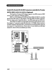
...---one IDE master and one IDE connector IDE3 and two serial connectors SATA1& SATA2. Each supports 1st generation serial ATA data rates of 150 MB/s. MS-6728 ATX Mainboard Serial ATA /Serial ATA RAID Connectors controlled by Promise 20378: IDE3, SATA3 & SATA4 (Optional) The brand new Promise 20378 chipset supports one IDE...
...---one IDE master and one IDE connector IDE3 and two serial connectors SATA1& SATA2. Each supports 1st generation serial ATA data rates of 150 MB/s. MS-6728 ATX Mainboard Serial ATA /Serial ATA RAID Connectors controlled by Promise 20378: IDE3, SATA3 & SATA4 (Optional) The brand new Promise 20378 chipset supports one IDE...
User Guide
Page 43
MS-6728 ATX Mainboard CD-In Connector: JCD1 The connector is for 4-channel audio output. For more information on the S-Bracket, refer to remove the plug from the ...
MS-6728 ATX Mainboard CD-In Connector: JCD1 The connector is for 4-channel audio output. For more information on the S-Bracket, refer to remove the plug from the ...
User Guide
Page 45
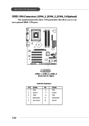
MS-6728 ATX Mainboard IEEE 1394 Connectors: J1394_1, J1394_2, J1394_3 (Optional) The mainboard provides three 1394 pin headers that allow you to right) J1394 Pin Definition PIN SIGNAL PIN 1 TPA+ 2 3 Ground 4 5 TPB+ 6 7 Cable power 8 9 Key (no pin) 10 SIGNAL TPAGround TPBCable power Ground 2-24 B ATT + 9 1 10 2 J1394_1, J1394_2, J1394_3 (from left to connect optional IEEE 1394 ports.
MS-6728 ATX Mainboard IEEE 1394 Connectors: J1394_1, J1394_2, J1394_3 (Optional) The mainboard provides three 1394 pin headers that allow you to right) J1394 Pin Definition PIN SIGNAL PIN 1 TPA+ 2 3 Ground 4 5 TPB+ 6 7 Cable power 8 9 Key (no pin) 10 SIGNAL TPAGround TPBCable power Ground 2-24 B ATT + 9 1 10 2 J1394_1, J1394_2, J1394_3 (from left to connect optional IEEE 1394 ports.


