User Guide
Page 5
Getting Started 1-1 Mainboard Specifications 1-2 Mainboard Layout 1-4 MSI Special Features 1-5 Super Pack 1-5 Core Center 1-6 Live BIOS™/Live Driver 1-8 Live Monitor 1-9 D-Bracket™ 2 (Optional 1-10 S-Bracket (Optional 1-12 ...Procedures for Socket 478 2-5 Installing the CPU Fan 2-5 Memory 2-7 Introduction to DDR SDRAM 2-7 DDR Population Rules 2-7 Installing DDR Modules 2-8 Power Supply 2-9 ATX 20-Pin Power Connector: ATX1 2-9 v CONTENTS FCC-B Radio Frequency Interference Statement iii Copyright Notice iii Revision History iii Safety Instructions v Chapter 1.
Getting Started 1-1 Mainboard Specifications 1-2 Mainboard Layout 1-4 MSI Special Features 1-5 Super Pack 1-5 Core Center 1-6 Live BIOS™/Live Driver 1-8 Live Monitor 1-9 D-Bracket™ 2 (Optional 1-10 S-Bracket (Optional 1-12 ...Procedures for Socket 478 2-5 Installing the CPU Fan 2-5 Memory 2-7 Introduction to DDR SDRAM 2-7 DDR Population Rules 2-7 Installing DDR Modules 2-8 Power Supply 2-9 ATX 20-Pin Power Connector: ATX1 2-9 v CONTENTS FCC-B Radio Frequency Interference Statement iii Copyright Notice iii Revision History iii Safety Instructions v Chapter 1.

User Guide
Page 8
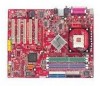
Designed to fit the advanced Intel® Pentium® 4 processors in 478 pin package, the 865 PE/G Neo2 delivers a high performance and professional desktop platform solution. 1-1 X ATX mainboard. Getting Started Getting Started Thank you for optimal system efficiency. The 865 PE/G Neo2 is based on Intel® 865PE/ G & ICH5 chipsets for choosing the 865 PE/G Neo2 (MS-6728) v1. Getting Started Chapter 1.
Designed to fit the advanced Intel® Pentium® 4 processors in 478 pin package, the 865 PE/G Neo2 delivers a high performance and professional desktop platform solution. 1-1 X ATX mainboard. Getting Started Getting Started Thank you for optimal system efficiency. The 865 PE/G Neo2 is based on Intel® 865PE/ G & ICH5 chipsets for choosing the 865 PE/G Neo2 (MS-6728) v1. Getting Started Chapter 1.
User Guide
Page 9
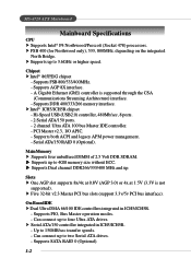
Chipset h Intel® 865PE/G chipset - Slots h One AGP slot supports 8x/4x at 0.8V (AGP 3.0) or 4x at 1.5V (3.3V is supported through the CSA (Communications Streaming Architecture) interface. - ... PCI bus slots (support 3.3v/5v PCI bus interface). Up to two Serial ATA drives. - Can connect up to four Ultra ATA drives. MS-6728 ATX Mainboard Mainboard Specifications CPU h Supports Intel® P4 Northwood/Prescott (Socket 478) processors. Supports AGP 8X interface. - Supports both ACPI and legacy APM power management. - h Supports up...
Chipset h Intel® 865PE/G chipset - Slots h One AGP slot supports 8x/4x at 0.8V (AGP 3.0) or 4x at 1.5V (3.3V is supported through the CSA (Communications Streaming Architecture) interface. - ... PCI bus slots (support 3.3v/5v PCI bus interface). Up to two Serial ATA drives. - Can connect up to four Ultra ATA drives. MS-6728 ATX Mainboard Mainboard Specifications CPU h Supports Intel® P4 Northwood/Prescott (Socket 478) processors. Supports AGP 8X interface. - Supports both ACPI and legacy APM power management. - h Supports up...

User Guide
Page 10
...& Play" BIOS which records your mainboard specifications. Mounting h 9 mounting holes. 1-3 Integrated Fast Ethernet MAC and PHY in one chip. - Compliance with PCI 2.2. - Compliance with AC97 v2.2 Spec. - Supports ACPI Power Management. Dimension h ATX Form Factor: 30.5 cm (L) ...RJ45 LAN jack (Optional) - 3 IEEE 1394 pinheaders (Optional) Audio h 6 channels software audio codec C-Media 9739A. - h The mainboard provides a Desktop Management Interface (DMI) function which detects the peripheral devices and expansion cards of the board automatically. Getting Started Promise 20378 ...
...& Play" BIOS which records your mainboard specifications. Mounting h 9 mounting holes. 1-3 Integrated Fast Ethernet MAC and PHY in one chip. - Compliance with PCI 2.2. - Compliance with AC97 v2.2 Spec. - Supports ACPI Power Management. Dimension h ATX Form Factor: 30.5 cm (L) ...RJ45 LAN jack (Optional) - 3 IEEE 1394 pinheaders (Optional) Audio h 6 channels software audio codec C-Media 9739A. - h The mainboard provides a Desktop Management Interface (DMI) function which detects the peripheral devices and expansion cards of the board automatically. Getting Started Promise 20378 ...
User Guide
Page 11
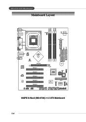
... 4 IDE 3 PROMISE PDC20378 S ATA 3 SFAN1 JA UD 1 JUSB2 (Optional) JUSB1 J1394_1 J1394_2 J1394_3 JFP2 JFP1 JIR1 865PE/G Neo2 (MS-6728) v1.X ATX Mainboard 1-4 AW AT X Power Supply IDE 1 FDD 1 T: Giga LAN jack B: USB ports JPW1 T: L in e - MS-6728 ATX Mainboard Mainboard Layout DIMM 1 DIMM 2 DIMM 3 DIMM 4 Top : mouse Bottom: keyboard USB ports Top : Parallel Port Bottom: COM...
... 4 IDE 3 PROMISE PDC20378 S ATA 3 SFAN1 JA UD 1 JUSB2 (Optional) JUSB1 J1394_1 J1394_2 J1394_3 JFP2 JFP1 JIR1 865PE/G Neo2 (MS-6728) v1.X ATX Mainboard 1-4 AW AT X Power Supply IDE 1 FDD 1 T: Giga LAN jack B: USB ports JPW1 T: L in e - MS-6728 ATX Mainboard Mainboard Layout DIMM 1 DIMM 2 DIMM 3 DIMM 4 Top : mouse Bottom: keyboard USB ports Top : Parallel Port Bottom: COM...
User Guide
Page 13
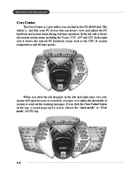
... the current system status including the Vcore, 3.3V, +5V and 12V. If you click the Core Center button in the CD-ROM disk. MS-6728 ATX Mainboard Core Center The Core Center is just like your PC doctor that can find in the top, a screen pops up for users to overclock, overspec...
... the current system status including the Vcore, 3.3V, +5V and 12V. If you click the Core Center button in the CD-ROM disk. MS-6728 ATX Mainboard Core Center The Core Center is just like your PC doctor that can find in the top, a screen pops up for users to overclock, overspec...
User Guide
Page 15
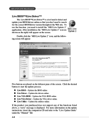
...support any of the screen. To use the function, you don't need to the "Live Update Guide" under the "Manual" Tab. 1-8 After installation, the "MSI Live Update 2" icon (as shown on the right) will appear: Five buttons are placed on the leftmost pane of the functions listed above, a "sorry" ... your BIOS/drivers online so that you need to start the update process. z Live BIOS - For more information on the screen. MS-6728 ATX Mainboard Live BIOS™/Live Driver™ The Live BIOS™/Live Driver™ is displayed. Click the desired button to search for the correct BIOS...
...support any of the screen. To use the function, you don't need to the "Live Update Guide" under the "Manual" Tab. 1-8 After installation, the "MSI Live Update 2" icon (as shown on the right) will appear: Five buttons are placed on the leftmost pane of the functions listed above, a "sorry" ... your BIOS/drivers online so that you need to start the update process. z Live BIOS - For more information on the screen. MS-6728 ATX Mainboard Live BIOS™/Live Driver™ The Live BIOS™/Live Driver™ is displayed. Click the desired button to search for the correct BIOS...
User Guide
Page 17
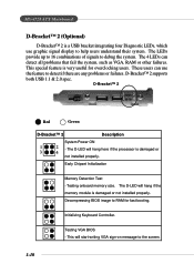
... all problems that fail the system, such as VGA, RAM or other failures. Early Chipset Initialization Memory Detection Test - Testing onboard memory size. MS-6728 ATX Mainboard D-Bracket™ 2 (Optional) D-Bracket™ 2 is very useful for fast booting. D-Bracket™ 2 1 2 3 4 Red Green D-Bracket™ 2 Description System Power ON 1 2 - The D-LED will hang...
... all problems that fail the system, such as VGA, RAM or other failures. Early Chipset Initialization Memory Detection Test - Testing onboard memory size. MS-6728 ATX Mainboard D-Bracket™ 2 (Optional) D-Bracket™ 2 is very useful for fast booting. D-Bracket™ 2 1 2 3 4 Red Green D-Bracket™ 2 Description System Power ON 1 2 - The D-LED will hang...
User Guide
Page 19
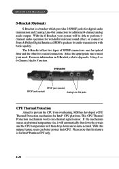
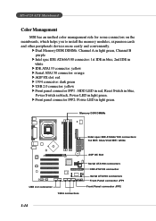
...With the S-Bracket, your need. If the mechanism senses an abnormal temperature rise, it will automatically shut down and resume normal. MS-6728 ATX Mainboard S-Bracket (Optional) S-Bracket is for Intel® Pentium CPU only. 1-12 Using 4- Please note that this unique feature, users can...temperature will be able to perform 6channel audio operation for wonderful surround sound effect, or connect to prevent the CPU from overheating, MSI has developed a CPU Thermal Protection mechanism for additional 4-channel analog audio output. For more information on a thermal signal sensor. or...
...With the S-Bracket, your need. If the mechanism senses an abnormal temperature rise, it will automatically shut down and resume normal. MS-6728 ATX Mainboard S-Bracket (Optional) S-Bracket is for Intel® Pentium CPU only. 1-12 Using 4- Please note that this unique feature, users can...temperature will be able to perform 6channel audio operation for wonderful surround sound effect, or connect to prevent the CPU from overheating, MSI has developed a CPU Thermal Protection mechanism for additional 4-channel analog audio output. For more information on a thermal signal sensor. or...
User Guide
Page 20
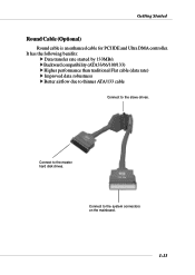
Connect to the system connectors on the mainboard. 1-13 Connect to the master hard disk drives. Getting Started Round Cable (Optional) Round cable is an enhanced cable for PCI IDE and Ultra DMA controller. It has the following benifits: h Data transfer rate started by 133MB/s h Backward compatibility (ATA33/66/100/133) h Higher performance than traditional Flat cable (data rate) h Improved data robustness h Better airflow due to thinner ATA/133 cable Connect to the slave drives.
Connect to the system connectors on the mainboard. 1-13 Connect to the master hard disk drives. Getting Started Round Cable (Optional) Round cable is an enhanced cable for PCI IDE and Ultra DMA controller. It has the following benifits: h Data transfer rate started by 133MB/s h Backward compatibility (ATA33/66/100/133) h Higher performance than traditional Flat cable (data rate) h Improved data robustness h Better airflow due to thinner ATA/133 cable Connect to the slave drives.
User Guide
Page 21
h Front panel connector JFP2: Power LED in light green. MS-6728 ATX Mainboard Color Management MSI has an unified color management rule for some connectors on the mainboards, which helps you to install the memory modules, expansion cards and other peripherals devices more easily and conveniently. Memory DDR DIMMs Intel spec IDE ATA66/...
h Front panel connector JFP2: Power LED in light green. MS-6728 ATX Mainboard Color Management MSI has an unified color management rule for some connectors on the mainboards, which helps you to install the memory modules, expansion cards and other peripherals devices more easily and conveniently. Memory DDR DIMMs Intel spec IDE ATA66/...
User Guide
Page 22
While doing the installation, be careful in holding the components and follow the installation procedures. 2-1 Hardware Setup Chapter 2. Hardware Setup Hardware Setup This chapter tells you how to install the CPU, memory modules, and expansion cards, as well as how to setup the jumpers on connecting the peripheral devices, such as the mouse, keyboard, etc. Also, it provides the instructions on the mainboard.
While doing the installation, be careful in holding the components and follow the installation procedures. 2-1 Hardware Setup Chapter 2. Hardware Setup Hardware Setup This chapter tells you how to install the CPU, memory modules, and expansion cards, as well as how to setup the jumpers on connecting the peripheral devices, such as the mouse, keyboard, etc. Also, it provides the instructions on the mainboard.
User Guide
Page 24
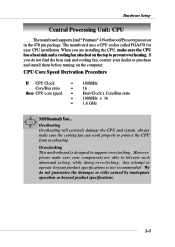
... able to protect the CPU from overheating. Overclocking This motherboard is not recommended. Overheating Overheating will seriously damage the ...Bus ratio = 16 then CPU core speed = Host Clock x Core/Bus ratio = 100MHz x 16 = 1.6 GHz MSI Reminds You... However, please make sure the CPU has a heat sink and a cooling fan attached on the computer. ...Any attempt to prevent overheating. Hardware Setup Central Processing Unit: CPU The mainboard supports Intel® Pentium® 4 Northwood/Prescott processor in the 478 pin package. We do not ...
... able to protect the CPU from overheating. Overclocking This motherboard is not recommended. Overheating Overheating will seriously damage the ...Bus ratio = 16 then CPU core speed = Host Clock x Core/Bus ratio = 100MHz x 16 = 1.6 GHz MSI Reminds You... However, please make sure the CPU has a heat sink and a cooling fan attached on the computer. ...Any attempt to prevent overheating. Hardware Setup Central Processing Unit: CPU The mainboard supports Intel® Pentium® 4 Northwood/Prescott processor in the 478 pin package. We do not ...
User Guide
Page 25
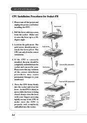
MS-6728 ATX Mainboard CPU Installation Procedures for the gold arrow. Please note that any violation of the CPU to your fingers pressing tightly on top of the correct ... degree Gold arrow Gold arrow Correct CPU placement O Gold arrow Incorrect CPU placement X Press down firmly into the socket and close the lever with your mainboard. 5. The CPU can not be seen. As the CPU is properly and completely embedded into the socket and can only fit in the correct orientation...
MS-6728 ATX Mainboard CPU Installation Procedures for the gold arrow. Please note that any violation of the CPU to your fingers pressing tightly on top of the correct ... degree Gold arrow Gold arrow Correct CPU placement O Gold arrow Incorrect CPU placement X Press down firmly into the socket and close the lever with your mainboard. 5. The CPU can not be seen. As the CPU is properly and completely embedded into the socket and can only fit in the correct orientation...
User Guide
Page 27
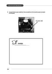
fan power cable NOTES 2-6 Connect the fan power cable from the mounted fan to the 3-pin fan power connector on the board. MS-6728 ATX Mainboard 5.
fan power cable NOTES 2-6 Connect the fan power cable from the mounted fan to the 3-pin fan power connector on the board. MS-6728 ATX Mainboard 5.
User Guide
Page 28
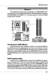
... note that each DIMM can install either single- Users can work respectively for 184-pin, 2.5V DDR DIMM with 8 memory banks. Hardware Setup Memory The mainboard provides 4 slots for single-channel DDR, but doubles the rate by SDR SDRAM. To operate properly, at least one DIMM module must be installed. DDR...
... note that each DIMM can install either single- Users can work respectively for 184-pin, 2.5V DDR DIMM with 8 memory banks. Hardware Setup Memory The mainboard provides 4 slots for single-channel DDR, but doubles the rate by SDR SDRAM. To operate properly, at least one DIMM module must be installed. DDR...
User Guide
Page 29
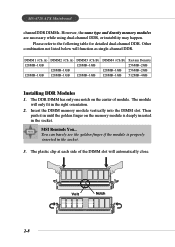
MSI Reminds You... Please refer to the following table for detailed dual-channel DDR. Other combination not listed below will only fit in until the golden ... (Ch B) 128MB~1GB 128MB~1GB System Density 256MB~2GB 256MB~2GB 512MB~4GB Installing DDR Modules 1. Then push it in the right orientation. 2. MS-6728 ATX Mainboard channelDDR DIMMs. However, the same type and density memory modules are necessary while using dual-channel DDR, or instability may happen. Volt Notch 2-8 The DDR...
MSI Reminds You... Please refer to the following table for detailed dual-channel DDR. Other combination not listed below will only fit in until the golden ... (Ch B) 128MB~1GB 128MB~1GB System Density 256MB~2GB 256MB~2GB 512MB~4GB Installing DDR Modules 1. Then push it in the right orientation. 2. MS-6728 ATX Mainboard channelDDR DIMMs. However, the same type and density memory modules are necessary while using dual-channel DDR, or instability may happen. Volt Notch 2-8 The DDR...
User Guide
Page 30
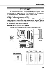
...all components are aligned. Then push down the power supply firmly into the connector. Hardware Setup Power Supply The mainboard supports ATX power supply for the power system. ATX 12V Power Connector: JPW1 This 12V power connector is inserted in the proper orientation and the pins are installed properly... to ensure that no damage will be caused. ATX 20-Pin Power Connector: ATX1 This connector allows you to connect to the CPU. 11 1 3 4 1 2 JPW1 20 10 BATT + ATX1 ...
...all components are aligned. Then push down the power supply firmly into the connector. Hardware Setup Power Supply The mainboard supports ATX power supply for the power system. ATX 12V Power Connector: JPW1 This 12V power connector is inserted in the proper orientation and the pins are installed properly... to ensure that no damage will be caused. ATX 20-Pin Power Connector: ATX1 This connector allows you to connect to the CPU. 11 1 3 4 1 2 JPW1 20 10 BATT + ATX1 ...
User Guide
Page 31
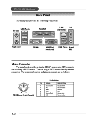
MS-6728 ATX Mainboard Back Panel The back panel provides the following connectors: USB Ports Mouse Parallel LAN L-in (Optional) Keyboard COMA VGA Port (Optional) USB Ports L-out MIC Mouse Connector The mainboard provides a standard PS/2® mouse mini DIN connector for attaching a PS/2® mouse. The connector location and pin assignments are as...
MS-6728 ATX Mainboard Back Panel The back panel provides the following connectors: USB Ports Mouse Parallel LAN L-in (Optional) Keyboard COMA VGA Port (Optional) USB Ports L-out MIC Mouse Connector The mainboard provides a standard PS/2® mouse mini DIN connector for attaching a PS/2® mouse. The connector location and pin assignments are as...

User Guide
Page 32
... Definition PIN SIGNAL DESCRIPTION 1 Keyboard DATA Keyboard DATA 2 NC No connection 3 GND Ground 4 VCC +5V 5 Keyboard Clock Keyboard clock 6 NC No connection USB Connectors The mainboard provides a UHCI (Universal Host Controller Interface) Universal Serial Bus root for attaching a PS/2® keyboard. Hardware Setup Keyboard Connector The...
... Definition PIN SIGNAL DESCRIPTION 1 Keyboard DATA Keyboard DATA 2 NC No connection 3 GND Ground 4 VCC +5V 5 Keyboard Clock Keyboard clock 6 NC No connection USB Connectors The mainboard provides a UHCI (Universal Host Controller Interface) Universal Serial Bus root for attaching a PS/2® keyboard. Hardware Setup Keyboard Connector The...


