User Guide
Page 8
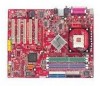
Designed to fit the advanced Intel® Pentium® 4 processors in 478 pin package, the 865 PE/G Neo2 delivers a high performance and professional desktop platform solution. 1-1 Getting Started Chapter 1. The 865 PE/G Neo2 is based on Intel® 865PE/ G & ICH5 chipsets for choosing the 865 PE/G Neo2 (MS-6728) v1. X ATX mainboard. Getting Started Getting Started Thank you for optimal system efficiency.
Designed to fit the advanced Intel® Pentium® 4 processors in 478 pin package, the 865 PE/G Neo2 delivers a high performance and professional desktop platform solution. 1-1 Getting Started Chapter 1. The 865 PE/G Neo2 is based on Intel® 865PE/ G & ICH5 chipsets for choosing the 865 PE/G Neo2 (MS-6728) v1. X ATX mainboard. Getting Started Getting Started Thank you for optimal system efficiency.
User Guide
Page 9
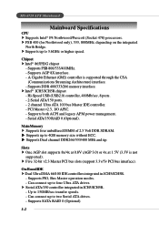
... Dual Ultra DMA 66/100 IDE controllers integrated in ICH5/ICH5R. - h Serial ATA/150 controller integrated in ICH5/ICH5R. - MS-6728 ATX Mainboard Mainboard Specifications CPU h Supports Intel® P4 Northwood/Prescott (Socket 478) processors. h Supports up to two Serial ATA drives. - Supports PIO... Serial ATA/150 ports. - 2 channel Ultra ATA 100 bus Master IDE controller. - Up to four Ultra ATA drives. Chipset h Intel® 865PE/G chipset - Supports AGP 8X interface. - Supports DDR 400/333/266 memory interface. h Intel® ICH5/ICH5R chipset - Supports both ACPI and...
... Dual Ultra DMA 66/100 IDE controllers integrated in ICH5/ICH5R. - h Serial ATA/150 controller integrated in ICH5/ICH5R. - MS-6728 ATX Mainboard Mainboard Specifications CPU h Supports Intel® P4 Northwood/Prescott (Socket 478) processors. h Supports up to two Serial ATA drives. - Supports PIO... Serial ATA/150 ports. - 2 channel Ultra ATA 100 bus Master IDE controller. - Up to four Ultra ATA drives. Chipset h Intel® 865PE/G chipset - Supports AGP 8X interface. - Supports DDR 400/333/266 memory interface. h Intel® ICH5/ICH5R chipset - Supports both ACPI and...
User Guide
Page 11
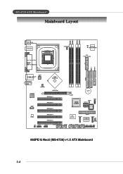
...AW AT X Power Supply IDE 1 FDD 1 T: Giga LAN jack B: USB ports JPW1 T: L in e - In M:Line-Out B:Mic NBFAN1 Intel 865PE/G AGP Slot Intel 547EI PCI Slot 1 JC D1 PCI Slot 2 PCI Slot 3 IDE 2 BATT + ICH5/ ICH5R JB AT1 S ATA 2 JD B1... PCI Slot 5 VIA VT6306 S ATA 4 IDE 3 PROMISE PDC20378 S ATA 3 SFAN1 JA UD 1 JUSB2 (Optional) JUSB1 J1394_1 J1394_2 J1394_3 JFP2 JFP1 JIR1 865PE/G Neo2 (MS-6728) v1.X ATX Mainboard 1-4 MS-6728 ATX Mainboard Mainboard Layout DIMM 1 DIMM 2 DIMM 3 DIMM 4 Top : mouse Bottom: keyboard USB ports Top : Parallel Port Bottom: COM A VGA Port (Optional) CP...
...AW AT X Power Supply IDE 1 FDD 1 T: Giga LAN jack B: USB ports JPW1 T: L in e - In M:Line-Out B:Mic NBFAN1 Intel 865PE/G AGP Slot Intel 547EI PCI Slot 1 JC D1 PCI Slot 2 PCI Slot 3 IDE 2 BATT + ICH5/ ICH5R JB AT1 S ATA 2 JD B1... PCI Slot 5 VIA VT6306 S ATA 4 IDE 3 PROMISE PDC20378 S ATA 3 SFAN1 JA UD 1 JUSB2 (Optional) JUSB1 J1394_1 J1394_2 J1394_3 JFP2 JFP1 JIR1 865PE/G Neo2 (MS-6728) v1.X ATX Mainboard 1-4 MS-6728 ATX Mainboard Mainboard Layout DIMM 1 DIMM 2 DIMM 3 DIMM 4 Top : mouse Bottom: keyboard USB ports Top : Parallel Port Bottom: COM A VGA Port (Optional) CP...
User Guide
Page 13
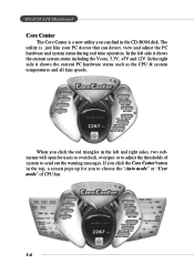
In the right side it shows the current system status including the Vcore, 3.3V, +5V and 12V. MS-6728 ATX Mainboard Core Center The Core Center is just like your PC doctor that can find in the CD-ROM disk. The utility is a new utility you ...
In the right side it shows the current system status including the Vcore, 3.3V, +5V and 12V. MS-6728 ATX Mainboard Core Center The Core Center is just like your PC doctor that can find in the CD-ROM disk. The utility is a new utility you ...
User Guide
Page 15
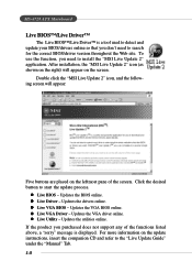
.... z Live Driver - Updates the VGA driver online. Click the desired button to install the "MSI Live Update 2" application. z Live BIOS - Updates the BIOS online. z Live VGA Driver - Double click the "MSI Live Update 2" icon, and the following screen will appear on the leftmost pane of the functions ... instructions, insert the companion CD and refer to search for the correct BIOS/driver version throughout the Web site. MS-6728 ATX Mainboard Live BIOS™/Live Driver™ The Live BIOS™/Live Driver™ is displayed. Updates the VGA BIOS online.
.... z Live Driver - Updates the VGA driver online. Click the desired button to install the "MSI Live Update 2" application. z Live BIOS - Updates the BIOS online. z Live VGA Driver - Double click the "MSI Live Update 2" icon, and the following screen will appear on the leftmost pane of the functions ... instructions, insert the companion CD and refer to search for the correct BIOS/driver version throughout the Web site. MS-6728 ATX Mainboard Live BIOS™/Live Driver™ The Live BIOS™/Live Driver™ is displayed. Updates the VGA BIOS online.
User Guide
Page 17
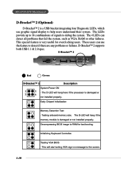
... D-Bracket™ 2 Description System Power ON 1 2 - The D-LED will hang here if the processor is damaged or not installed properly. Initializing Keyboard Controller. MS-6728 ATX Mainboard D-Bracket™ 2 (Optional) D-Bracket™ 2 is a USB bracket integrating four Diagnostic LEDs, which use the feature to the screen. 1-10 D-Bracket™ 2 supports both USB...
... D-Bracket™ 2 Description System Power ON 1 2 - The D-LED will hang here if the processor is damaged or not installed properly. Initializing Keyboard Controller. MS-6728 ATX Mainboard D-Bracket™ 2 (Optional) D-Bracket™ 2 is a USB bracket integrating four Diagnostic LEDs, which use the feature to the screen. 1-10 D-Bracket™ 2 supports both USB...
User Guide
Page 19
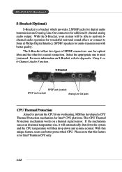
MS-6728 ATX Mainboard S-Bracket (Optional) S-Bracket is for Intel® Pentium CPU only. 1-12 Using 4- or 6-Channel Audio Function. With this feature is a bracket which provides 2 SPDIF jacks ... and the CPU temperature will be able to perform 6channel audio operation for wonderful surround sound effect, or connect to prevent the CPU from overheating, MSI has developed a CPU Thermal Protection mechanism for coaxial connection. The S-Bracket offers two types of SPDIF connectors: one to Appendix. Select the appropriate one for...
MS-6728 ATX Mainboard S-Bracket (Optional) S-Bracket is for Intel® Pentium CPU only. 1-12 Using 4- or 6-Channel Audio Function. With this feature is a bracket which provides 2 SPDIF jacks ... and the CPU temperature will be able to perform 6channel audio operation for wonderful surround sound effect, or connect to prevent the CPU from overheating, MSI has developed a CPU Thermal Protection mechanism for coaxial connection. The S-Bracket offers two types of SPDIF connectors: one to Appendix. Select the appropriate one for...
User Guide
Page 21
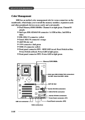
... LED in red, Reset Switch in blue, Power Switch in black, Power LED in light green. MS-6728 ATX Mainboard Color Management MSI has an unified color management rule for some connectors on the mainboards, which helps you to install the memory modules, expansion cards and other peripherals devices more easily and conveniently. Memory...
... LED in red, Reset Switch in blue, Power Switch in black, Power LED in light green. MS-6728 ATX Mainboard Color Management MSI has an unified color management rule for some connectors on the mainboards, which helps you to install the memory modules, expansion cards and other peripherals devices more easily and conveniently. Memory...
User Guide
Page 25
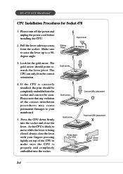
...Gold arrow Gold arrow Correct CPU placement O Gold arrow Incorrect CPU placement X Press down firmly into the socket and close the lever with your mainboard. 5. Look for Socket 478 1. As the CPU is likely to make sure the CPU is being closed, always close the lever. Press ...CPU to move while the lever is properly and completely embedded into the socket and can only fit in the correct orientation. 4. MS-6728 ATX Mainboard CPU Installation Procedures for the gold arrow. Please turn off the power and unplug the power cord before installing the CPU. 2. Make sure...
...Gold arrow Gold arrow Correct CPU placement O Gold arrow Incorrect CPU placement X Press down firmly into the socket and close the lever with your mainboard. 5. Look for Socket 478 1. As the CPU is likely to make sure the CPU is being closed, always close the lever. Press ...CPU to move while the lever is properly and completely embedded into the socket and can only fit in the correct orientation. 4. MS-6728 ATX Mainboard CPU Installation Procedures for the gold arrow. Please turn off the power and unplug the power cord before installing the CPU. 2. Make sure...
User Guide
Page 27
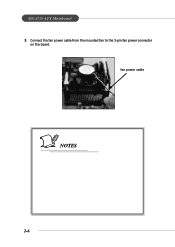
MS-6728 ATX Mainboard 5. Connect the fan power cable from the mounted fan to the 3-pin fan power connector on the board. fan power cable NOTES 2-6
MS-6728 ATX Mainboard 5. Connect the fan power cable from the mounted fan to the 3-pin fan power connector on the board. fan power cable NOTES 2-6
User Guide
Page 29
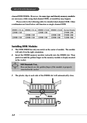
... The module will automatically close. The DDR DIMM has only one notch on the memory module is properly inserted in the right orientation. 2. MSI Reminds You... Please refer to the following table for detailed dual-channel DDR. Other combination not listed below will function as single-channel DDR....128MB~1GB 128MB~1GB DIMM4 (Ch B) 128MB~1GB 128MB~1GB System Density 256MB~2GB 256MB~2GB 512MB~4GB Installing DDR Modules 1. MS-6728 ATX Mainboard channelDDR DIMMs. However, the same type and density memory modules are necessary while using dual-channel DDR, or instability may happen.
... The module will automatically close. The DDR DIMM has only one notch on the memory module is properly inserted in the right orientation. 2. MSI Reminds You... Please refer to the following table for detailed dual-channel DDR. Other combination not listed below will function as single-channel DDR....128MB~1GB 128MB~1GB DIMM4 (Ch B) 128MB~1GB 128MB~1GB System Density 256MB~2GB 256MB~2GB 512MB~4GB Installing DDR Modules 1. MS-6728 ATX Mainboard channelDDR DIMMs. However, the same type and density memory modules are necessary while using dual-channel DDR, or instability may happen.
User Guide
Page 31
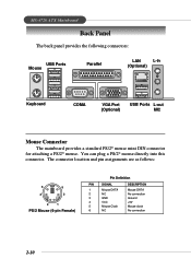
... 6 NC DESCRIPTION Mouse DATA No connection Ground +5V Mouse clock No connection 2-10 You can plug a PS/2® mouse directly into this connector. MS-6728 ATX Mainboard Back Panel The back panel provides the following connectors: USB Ports Mouse Parallel LAN L-in (Optional) Keyboard COMA VGA Port (Optional) USB Ports L-out MIC...
... 6 NC DESCRIPTION Mouse DATA No connection Ground +5V Mouse clock No connection 2-10 You can plug a PS/2® mouse directly into this connector. MS-6728 ATX Mainboard Back Panel The back panel provides the following connectors: USB Ports Mouse Parallel LAN L-in (Optional) Keyboard COMA VGA Port (Optional) USB Ports L-out MIC...
User Guide
Page 33
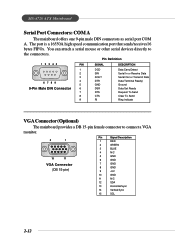
MS-6728 ATX Mainboard Serial Port Connectors: COM A The mainboard offers one 9-pin male DIN connectors as serial port COM A. Pin Definition 1 2 3 4 5 PIN SIGNAL DESCRIPTION 1 2 3 4 6 7 8 9 5 9-Pin Male DIN Connector 6 7 8 9 DCD SIN SOUT DTR GND DSR ... Data Serial Out or Transmit Data Data Terminal Ready) Ground Data Set Ready Request To Send Clear To Send Ring Indicate VGA Connector (Optional) The mainboard provides a DB 15-pin female connector to the connectors. The port is a 16550A high speed communication port that sends/receives16 bytes FIFOs. You can attach...
MS-6728 ATX Mainboard Serial Port Connectors: COM A The mainboard offers one 9-pin male DIN connectors as serial port COM A. Pin Definition 1 2 3 4 5 PIN SIGNAL DESCRIPTION 1 2 3 4 6 7 8 9 5 9-Pin Male DIN Connector 6 7 8 9 DCD SIN SOUT DTR GND DSR ... Data Serial Out or Transmit Data Data Terminal Ready) Ground Data Set Ready Request To Send Clear To Send Ring Indicate VGA Connector (Optional) The mainboard provides a DB 15-pin female connector to the connectors. The port is a 16550A high speed communication port that sends/receives16 bytes FIFOs. You can attach...
User Guide
Page 35
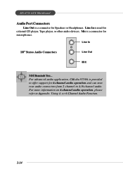
... audio application, CMedia 9739A is used for external CD player, Tape player, or other audio devices. Mic is a connector for Speakers or Headphones. MS-6728 ATX Mainboard Audio Port Connectors Line Out is a connector for microphones. Line In 1/8" Stereo Audio Connectors Line Out MIC...
... audio application, CMedia 9739A is used for external CD player, Tape player, or other audio devices. Mic is a connector for Speakers or Headphones. MS-6728 ATX Mainboard Audio Port Connectors Line Out is a connector for microphones. Line In 1/8" Stereo Audio Connectors Line Out MIC...
User Guide
Page 37
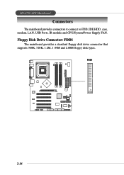
FDD1 B ATT + 2-16 MS-6728 ATX Mainboard Connectors The mainboard provides connectors to connect to FDD, IDE HDD, case, modem, LAN, USB Ports, IR module and CPU/System/Power Supply FAN. Floppy Disk Drive Connector: FDD1 The mainboard provides a standard floppy disk drive connector that supports 360K, 720K, 1.2M, 1.44M and 2.88M floppy disk types.
FDD1 B ATT + 2-16 MS-6728 ATX Mainboard Connectors The mainboard provides connectors to connect to FDD, IDE HDD, case, modem, LAN, USB Ports, IR module and CPU/System/Power Supply FAN. Floppy Disk Drive Connector: FDD1 The mainboard provides a standard floppy disk drive connector that supports 360K, 720K, 1.2M, 1.44M and 2.88M floppy disk types.
User Guide
Page 39
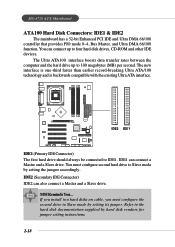
... other IDE devices. IDE2 (Secondary IDE Connector) IDE2 can connect a Master and a Slave drive. Refer to IDE1. MS-6728 ATX Mainboard ATA100 Hard Disk Connectors: IDE1 & IDE2 The mainboard has a 32-bit Enhanced PCI IDE and Ultra DMA 66/100 controller that provides PIO mode 0~4, Bus Master, and Ultra DMA... 66/100 function. The Ultra ATA100 interface boosts data transfer rates between the computer and the hard drive up to 100 megabytes (MB) per second. MSI Reminds...
... other IDE devices. IDE2 (Secondary IDE Connector) IDE2 can connect a Master and a Slave drive. Refer to IDE1. MS-6728 ATX Mainboard ATA100 Hard Disk Connectors: IDE1 & IDE2 The mainboard has a 32-bit Enhanced PCI IDE and Ultra DMA 66/100 controller that provides PIO mode 0~4, Bus Master, and Ultra DMA... 66/100 function. The Ultra ATA100 interface boosts data transfer rates between the computer and the hard drive up to 100 megabytes (MB) per second. MSI Reminds...
User Guide
Page 41
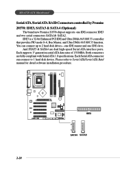
... ATA connector can connect up to 2 hard disk drives---one IDE master and one IDE connector IDE3 and two serial connectors SATA1& SATA2. MS-6728 ATX Mainboard Serial ATA /Serial ATA RAID Connectors controlled by Promise 20378: IDE3, SATA3 & SATA4 (Optional) The brand new Promise 20378 chipset supports one IDE slave. Please...
... ATA connector can connect up to 2 hard disk drives---one IDE master and one IDE connector IDE3 and two serial connectors SATA1& SATA2. MS-6728 ATX Mainboard Serial ATA /Serial ATA RAID Connectors controlled by Promise 20378: IDE3, SATA3 & SATA4 (Optional) The brand new Promise 20378 chipset supports one IDE slave. Please...
User Guide
Page 43
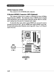
... Line-Out jacks for CD-ROM audio connector. For more information on the S-Bracket, refer to remove the plug from the jack first. MS-6728 ATX Mainboard CD-In Connector: JCD1 The connector is for 4-channel audio output. S-Bracket (SPDIF) Connector: JSP1 (Optional) The connector allows you need to Appendix: Using...
... Line-Out jacks for CD-ROM audio connector. For more information on the S-Bracket, refer to remove the plug from the jack first. MS-6728 ATX Mainboard CD-In Connector: JCD1 The connector is for 4-channel audio output. S-Bracket (SPDIF) Connector: JSP1 (Optional) The connector allows you need to Appendix: Using...
User Guide
Page 45
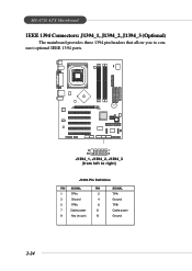
MS-6728 ATX Mainboard IEEE 1394 Connectors: J1394_1, J1394_2, J1394_3 (Optional) The mainboard provides three 1394 pin headers that allow you to right) J1394 Pin Definition PIN SIGNAL PIN 1 TPA+ 2 3 Ground 4 5 TPB+ 6 7 Cable power 8 9 Key (no pin) 10 SIGNAL TPAGround TPBCable power Ground 2-24 B ATT + 9 1 10 2 J1394_1, J1394_2, J1394_3 (from left to connect optional IEEE 1394 ports.
MS-6728 ATX Mainboard IEEE 1394 Connectors: J1394_1, J1394_2, J1394_3 (Optional) The mainboard provides three 1394 pin headers that allow you to right) J1394 Pin Definition PIN SIGNAL PIN 1 TPA+ 2 3 Ground 4 5 TPB+ 6 7 Cable power 8 9 Key (no pin) 10 SIGNAL TPAGround TPBCable power Ground 2-24 B ATT + 9 1 10 2 J1394_1, J1394_2, J1394_3 (from left to connect optional IEEE 1394 ports.
User Guide
Page 47
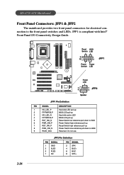
...-down to the front panel switches and LEDs. JFP2 Pin Definition PIN SIGNAL 1 GND 3 SLED 5 PLED 7 NC PIN SIGNAL 2 SPK- 4 BUZ+ 6 BUZ- 8 SPK+ MS-6728 ATX Mainboard Front Panel Connectors: JFP1 & JFP2 The mainboard provides two front panel connectors for electrical connection to GND Reserved. Do not use.
...-down to the front panel switches and LEDs. JFP2 Pin Definition PIN SIGNAL 1 GND 3 SLED 5 PLED 7 NC PIN SIGNAL 2 SPK- 4 BUZ+ 6 BUZ- 8 SPK+ MS-6728 ATX Mainboard Front Panel Connectors: JFP1 & JFP2 The mainboard provides two front panel connectors for electrical connection to GND Reserved. Do not use.


