
User Guide
Page 10
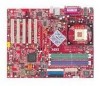
h Connect up to 2 Serial ATA devices and 2 Ultra ATA 133 devices. On-Board Peripherals h On-Board Peripherals include: - 1 floppy port supports 2 FDDs with AC97 v2.2 Spec. - Compliance with 360K, 720K, 1.2M, 1.44M and 2.88Mbytes - 1 serial port COM1, 1 VGA port (for Intel® 82547EI). - Integrated Fast Ethernet MAC and PHY in one ... Ultra ATA, Serial ATA, Ultra ATA RAID 0 or 1 , Serial ATA RAID 0 or 1, Ultra/Serial ATA RAID 0+1 supported. Can support SPDIF Out via S-Bracket only. Dimension h ATX Form Factor: 30.5 cm (L) x 24.4 cm (W).
h Connect up to 2 Serial ATA devices and 2 Ultra ATA 133 devices. On-Board Peripherals h On-Board Peripherals include: - 1 floppy port supports 2 FDDs with AC97 v2.2 Spec. - Compliance with 360K, 720K, 1.2M, 1.44M and 2.88Mbytes - 1 serial port COM1, 1 VGA port (for Intel® 82547EI). - Integrated Fast Ethernet MAC and PHY in one ... Ultra ATA, Serial ATA, Ultra ATA RAID 0 or 1 , Serial ATA RAID 0 or 1, Ultra/Serial ATA RAID 0+1 supported. Can support SPDIF Out via S-Bracket only. Dimension h ATX Form Factor: 30.5 cm (L) x 24.4 cm (W).
User Guide
Page 17
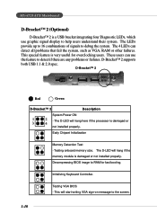
The D-LED will hang here if the processor is damaged or 3 4 not installed properly. Testing VGA BIOS - MS-6728 ATX Mainboard D-Bracket™ 2 (Optional) D-Bracket™ 2 is a USB bracket integrating four Diagnostic LEDs, which use the feature to detect if there are any problems or .... This will start writing VGA sign-on message to help users understand their system. Early Chipset Initialization Memory Detection Test - D-Bracket™ 2 supports both USB 1.1 & 2.0 spec. These users can detect all problems that fail the system, such as VGA, RAM or other failures.
The D-LED will hang here if the processor is damaged or 3 4 not installed properly. Testing VGA BIOS - MS-6728 ATX Mainboard D-Bracket™ 2 (Optional) D-Bracket™ 2 is a USB bracket integrating four Diagnostic LEDs, which use the feature to detect if there are any problems or .... This will start writing VGA sign-on message to help users understand their system. Early Chipset Initialization Memory Detection Test - D-Bracket™ 2 supports both USB 1.1 & 2.0 spec. These users can detect all problems that fail the system, such as VGA, RAM or other failures.
User Guide
Page 21
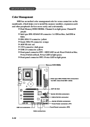
...Serial ATA150 connectors Front Panel connector JFP1 Front Panel connector JFP2 1-14 h Dual Memory DDR DIMMs: Channel A in light green, Channel B purple h Intel spec IDE ATA66/100 connector: 1st IDE in blue, 2nd IDE in white h IDE ATA133 connector: yellow h Serial ATA150 connector: orange h AGP 8X slot:... Power Switch in black, Power LED in light green. h Front panel connector JFP2: Power LED in light green. MS-6728 ATX Mainboard Color Management MSI has an unified color management rule for some connectors on the mainboards, which helps you to install the memory modules, expansion cards ...
...Serial ATA150 connectors Front Panel connector JFP1 Front Panel connector JFP2 1-14 h Dual Memory DDR DIMMs: Channel A in light green, Channel B purple h Intel spec IDE ATA66/100 connector: 1st IDE in blue, 2nd IDE in white h IDE ATA133 connector: yellow h Serial ATA150 connector: orange h AGP 8X slot:... Power Switch in black, Power LED in light green. h Front panel connector JFP2: Power LED in light green. MS-6728 ATX Mainboard Color Management MSI has an unified color management rule for some connectors on the mainboards, which helps you to install the memory modules, expansion cards ...
User Guide
Page 49
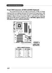
... Definition PIN SIGNAL PIN SIGNAL 1 VCC 2 VCC 3 USB0- 4 USB1- 5 USB0+ 6 USB1+ 7 GND 8 GND 9 Key (no pin) 10 USBOC 2 10 1 9 JUSB2, JUSB1 (USB 2.0/Intel spec) 2-28 MS-6728 ATX Mainboard Front USB Connectors: JUSB1 & JUSB2 (Optional) The mainboard provides two USB 2.0 pin headers JUSB1 & JUSB2 (Optional) that are compliant with Intel® I/O Connectivity...
... Definition PIN SIGNAL PIN SIGNAL 1 VCC 2 VCC 3 USB0- 4 USB1- 5 USB0+ 6 USB1+ 7 GND 8 GND 9 Key (no pin) 10 USBOC 2 10 1 9 JUSB2, JUSB1 (USB 2.0/Intel spec) 2-28 MS-6728 ATX Mainboard Front USB Connectors: JUSB1 & JUSB2 (Optional) The mainboard provides two USB 2.0 pin headers JUSB1 & JUSB2 (Optional) that are compliant with Intel® I/O Connectivity...
User Guide
Page 50
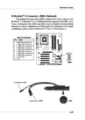
... DBracket™ 2. It integrates four LEDs and allows users to D-Bracket™ 2 at P.1-10 in Chapter 1. D-Bracket™ 2 is a USB Bracket that supports both USB1.1 & 2. 0 spec. For definitions of 16 signal combinations, please refer to identify system problem through 16 various combinations of LED signals. Hardware Setup D-Bracket™ 2 Connector: JDB1...
... DBracket™ 2. It integrates four LEDs and allows users to D-Bracket™ 2 at P.1-10 in Chapter 1. D-Bracket™ 2 is a USB Bracket that supports both USB1.1 & 2. 0 spec. For definitions of 16 signal combinations, please refer to identify system problem through 16 various combinations of LED signals. Hardware Setup D-Bracket™ 2 Connector: JDB1...
