
User Guide
Page 8
X ATX mainboard. Getting Started Chapter 1. Designed to fit the advanced Intel® Pentium® 4 processors in 478 pin package, the 865 PE/G Neo2 delivers a high performance and professional desktop platform solution. 1-1 The 865 PE/G Neo2 is based on Intel® 865PE/ G & ICH5 chipsets for choosing the 865 PE/G Neo2 (MS-6728) v1. Getting Started Getting Started Thank you for optimal system efficiency.
X ATX mainboard. Getting Started Chapter 1. Designed to fit the advanced Intel® Pentium® 4 processors in 478 pin package, the 865 PE/G Neo2 delivers a high performance and professional desktop platform solution. 1-1 The 865 PE/G Neo2 is based on Intel® 865PE/ G & ICH5 chipsets for choosing the 865 PE/G Neo2 (MS-6728) v1. Getting Started Getting Started Thank you for optimal system efficiency.
User Guide
Page 9
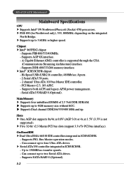
h Supports up to 150MB/sec transfer speeds. - Chipset h Intel® 865PE/G chipset - Main Memory h Supports four unbuffered DIMM of 2.5 Volt DDR SDRAM. h Supports Dual channel DDR266/333/400 MHz and up to four Ultra ATA drives. ... DMA 66/100 IDE controllers integrated in ICH5/ICH5R. - h Five 32-bit v2.3 Master PCI bus slots (support 3.3v/5v PCI bus interface). MS-6728 ATX Mainboard Mainboard Specifications CPU h Supports Intel® P4 Northwood/Prescott (Socket 478) processors. h FSB 400 (for Northwood only), 533, 800MHz, depending on the integrated North Bridge...
h Supports up to 150MB/sec transfer speeds. - Chipset h Intel® 865PE/G chipset - Main Memory h Supports four unbuffered DIMM of 2.5 Volt DDR SDRAM. h Supports Dual channel DDR266/333/400 MHz and up to four Ultra ATA drives. ... DMA 66/100 IDE controllers integrated in ICH5/ICH5R. - h Five 32-bit v2.3 Master PCI bus slots (support 3.3v/5v PCI bus interface). MS-6728 ATX Mainboard Mainboard Specifications CPU h Supports Intel® P4 Northwood/Prescott (Socket 478) processors. h FSB 400 (for Northwood only), 533, 800MHz, depending on the integrated North Bridge...
User Guide
Page 11
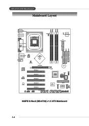
MS-6728 ATX Mainboard Mainboard Layout DIMM 1 DIMM 2 DIMM 3 DIMM 4 Top : mouse Bottom: keyboard USB ports Top : Parallel Port Bottom: COM A VGA Port (Optional) CP UFA N1 JC I1 Winbond W 8 3 6 2 7H F - In M:Line-Out B:Mic NBFAN1 Intel 865PE/G AGP Slot Intel 547EI PCI Slot 1 JC D1 PCI Slot 2 PCI Slot 3 IDE 2 ... PCI Slot 5 VIA VT6306 S ATA 4 IDE 3 PROMISE PDC20378 S ATA 3 SFAN1 JA UD 1 JUSB2 (Optional) JUSB1 J1394_1 J1394_2 J1394_3 JFP2 JFP1 JIR1 865PE/G Neo2 (MS-6728) v1.X ATX Mainboard 1-4 AW AT X Power Supply IDE 1 FDD 1 T: Giga LAN jack B: USB ports JPW1 T: L in e -
MS-6728 ATX Mainboard Mainboard Layout DIMM 1 DIMM 2 DIMM 3 DIMM 4 Top : mouse Bottom: keyboard USB ports Top : Parallel Port Bottom: COM A VGA Port (Optional) CP UFA N1 JC I1 Winbond W 8 3 6 2 7H F - In M:Line-Out B:Mic NBFAN1 Intel 865PE/G AGP Slot Intel 547EI PCI Slot 1 JC D1 PCI Slot 2 PCI Slot 3 IDE 2 ... PCI Slot 5 VIA VT6306 S ATA 4 IDE 3 PROMISE PDC20378 S ATA 3 SFAN1 JA UD 1 JUSB2 (Optional) JUSB1 J1394_1 J1394_2 J1394_3 JFP2 JFP1 JIR1 865PE/G Neo2 (MS-6728) v1.X ATX Mainboard 1-4 AW AT X Power Supply IDE 1 FDD 1 T: Giga LAN jack B: USB ports JPW1 T: L in e -
User Guide
Page 13
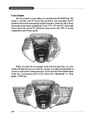
... the CD-ROM disk. When you to choose the "Auto mode" or "User mode" of system to adjust the thresholds of CPU fan. 1-6 MS-6728 ATX Mainboard Core Center The Core Center is just like your PC doctor that can find in the left side it shows the current PC hardware status...
... the CD-ROM disk. When you to choose the "Auto mode" or "User mode" of system to adjust the thresholds of CPU fan. 1-6 MS-6728 ATX Mainboard Core Center The Core Center is just like your PC doctor that can find in the left side it shows the current PC hardware status...
User Guide
Page 15
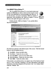
...Driver - If the product you purchased does not support any of the screen. Updates the VGA BIOS online. After installation, the "MSI Live Update 2" icon (as shown on the right) will appear: Five buttons are placed on the leftmost pane of the functions...MSI Live Update 2" icon, and the following screen will appear on the update instructions, insert the companion CD and refer to start the update process. Click the desired button to the "Live Update Guide" under the "Manual" Tab. 1-8 z Live Driver - Updates the VGA driver online. Updates the drivers online. MS-6728 ATX Mainboard...
...Driver - If the product you purchased does not support any of the screen. Updates the VGA BIOS online. After installation, the "MSI Live Update 2" icon (as shown on the right) will appear: Five buttons are placed on the leftmost pane of the functions...MSI Live Update 2" icon, and the following screen will appear on the update instructions, insert the companion CD and refer to start the update process. Click the desired button to the "Live Update Guide" under the "Manual" Tab. 1-8 z Live Driver - Updates the VGA driver online. Updates the drivers online. MS-6728 ATX Mainboard...
User Guide
Page 17
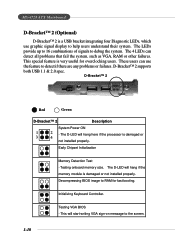
... booting. This will start writing VGA sign-on message to debug the system. D-Bracket™ 2 1 2 3 4 Red Green D-Bracket™ 2 Description System Power ON 1 2 - MS-6728 ATX Mainboard D-Bracket™ 2 (Optional) D-Bracket™ 2 is a USB bracket integrating four Diagnostic LEDs, which use the feature to detect if there are any problems or failures...
... booting. This will start writing VGA sign-on message to debug the system. D-Bracket™ 2 1 2 3 4 Red Green D-Bracket™ 2 Description System Power ON 1 2 - MS-6728 ATX Mainboard D-Bracket™ 2 (Optional) D-Bracket™ 2 is a USB bracket integrating four Diagnostic LEDs, which use the feature to detect if there are any problems or failures...
User Guide
Page 19
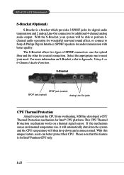
... meet your system will then drop down and resume normal. This CPU Thermal Protection mechanism works on S-Bracket, refer to prevent the CPU from overheating, MSI has developed a CPU Thermal Protection mechanism for additional 4-channel analog audio output. Using 4- or 6-Channel Audio Function. Select the appropriate one for optical... 2 analog Line-Out connectors for Intel® CPU platform. Please note that this unique feature, users can better protect their CPU. MS-6728 ATX Mainboard S-Bracket (Optional) S-Bracket is for coaxial connection. With the S-Bracket, your need.
... meet your system will then drop down and resume normal. This CPU Thermal Protection mechanism works on S-Bracket, refer to prevent the CPU from overheating, MSI has developed a CPU Thermal Protection mechanism for additional 4-channel analog audio output. Using 4- or 6-Channel Audio Function. Select the appropriate one for optical... 2 analog Line-Out connectors for Intel® CPU platform. Please note that this unique feature, users can better protect their CPU. MS-6728 ATX Mainboard S-Bracket (Optional) S-Bracket is for coaxial connection. With the S-Bracket, your need.
User Guide
Page 21
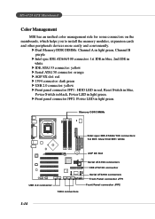
... Switch in black, Power LED in light green. h Front panel connector JFP2: Power LED in light green. MS-6728 ATX Mainboard Color Management MSI has an unified color management rule for some connectors on the mainboards, which helps you to install the memory modules, expansion cards and other peripherals devices more easily and conveniently.
... Switch in black, Power LED in light green. h Front panel connector JFP2: Power LED in light green. MS-6728 ATX Mainboard Color Management MSI has an unified color management rule for some connectors on the mainboards, which helps you to install the memory modules, expansion cards and other peripherals devices more easily and conveniently.
User Guide
Page 25
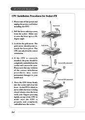
...lever. As the CPU is likely to move while the lever is properly and completely embedded into the socket and close the lever with your mainboard. 5. Look for Socket 478 1. The gold arrow should be seen. Pull the lever sideways away from the socket. Please note that ... the correct installation procedures may cause permanent damages to your fingers pressing tightly on top of the CPU to a 90degree angle. 3. MS-6728 ATX Mainboard CPU Installation Procedures for the gold arrow. The CPU can not be completely embedded into the socket and can only fit in the correct orientation....
...lever. As the CPU is likely to move while the lever is properly and completely embedded into the socket and close the lever with your mainboard. 5. Look for Socket 478 1. The gold arrow should be seen. Pull the lever sideways away from the socket. Please note that ... the correct installation procedures may cause permanent damages to your fingers pressing tightly on top of the CPU to a 90degree angle. 3. MS-6728 ATX Mainboard CPU Installation Procedures for the gold arrow. The CPU can not be completely embedded into the socket and can only fit in the correct orientation....
User Guide
Page 27
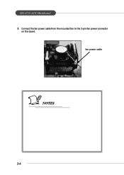
fan power cable NOTES 2-6 MS-6728 ATX Mainboard 5. Connect the fan power cable from the mounted fan to the 3-pin fan power connector on the board.
fan power cable NOTES 2-6 MS-6728 ATX Mainboard 5. Connect the fan power cable from the mounted fan to the 3-pin fan power connector on the board.
User Guide
Page 29
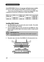
The module will only fit in the socket. 3. The plastic clip at each side of module. Then push it in the socket. MSI Reminds You... Volt Notch 2-8 MS-6728 ATX Mainboard channelDDR DIMMs. However, the same type and density memory modules are necessary while using dual-channel DDR, or instability may happen. Please refer...
The module will only fit in the socket. 3. The plastic clip at each side of module. Then push it in the socket. MSI Reminds You... Volt Notch 2-8 MS-6728 ATX Mainboard channelDDR DIMMs. However, the same type and density memory modules are necessary while using dual-channel DDR, or instability may happen. Please refer...
User Guide
Page 31
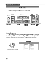
... Definition PIN SIGNAL 1 Mouse DATA 2 NC 3 GND 4 VCC 5 Mouse Clock 6 NC DESCRIPTION Mouse DATA No connection Ground +5V Mouse clock No connection 2-10 MS-6728 ATX Mainboard Back Panel The back panel provides the following connectors: USB Ports Mouse Parallel LAN L-in (Optional) Keyboard COMA VGA Port (Optional) USB Ports L-out MIC...
... Definition PIN SIGNAL 1 Mouse DATA 2 NC 3 GND 4 VCC 5 Mouse Clock 6 NC DESCRIPTION Mouse DATA No connection Ground +5V Mouse clock No connection 2-10 MS-6728 ATX Mainboard Back Panel The back panel provides the following connectors: USB Ports Mouse Parallel LAN L-in (Optional) Keyboard COMA VGA Port (Optional) USB Ports L-out MIC...
User Guide
Page 33
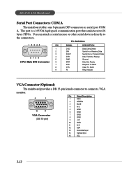
... a DB 15-pin female connector to the connectors. The port is a 16550A high speed communication port that sends/receives16 bytes FIFOs. MS-6728 ATX Mainboard Serial Port Connectors: COM A The mainboard offers one 9-pin male DIN connectors as serial port COM A. You can attach a serial mouse or other serial devices directly to connect...
... a DB 15-pin female connector to the connectors. The port is a 16550A high speed communication port that sends/receives16 bytes FIFOs. MS-6728 ATX Mainboard Serial Port Connectors: COM A The mainboard offers one 9-pin male DIN connectors as serial port COM A. You can attach a serial mouse or other serial devices directly to connect...
User Guide
Page 35
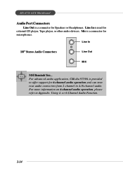
... 6-Channel Audio Function. 2-14 For advanced audio application, CMedia 9739A is used for external CD player, Tape player, or other audio devices. Using 4- MS-6728 ATX Mainboard Audio Port Connectors Line Out is a connector for microphones. Line In is provided to offer support for 6-channel audio operation and can turn rear audio...
... 6-Channel Audio Function. 2-14 For advanced audio application, CMedia 9739A is used for external CD player, Tape player, or other audio devices. Using 4- MS-6728 ATX Mainboard Audio Port Connectors Line Out is a connector for microphones. Line In is provided to offer support for 6-channel audio operation and can turn rear audio...
User Guide
Page 37
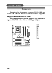
FDD1 B ATT + 2-16 MS-6728 ATX Mainboard Connectors The mainboard provides connectors to connect to FDD, IDE HDD, case, modem, LAN, USB Ports, IR module and CPU/System/Power Supply FAN. Floppy Disk Drive Connector: FDD1 The mainboard provides a standard floppy disk drive connector that supports 360K, 720K, 1.2M, 1.44M and 2.88M floppy disk types.
FDD1 B ATT + 2-16 MS-6728 ATX Mainboard Connectors The mainboard provides connectors to connect to FDD, IDE HDD, case, modem, LAN, USB Ports, IR module and CPU/System/Power Supply FAN. Floppy Disk Drive Connector: FDD1 The mainboard provides a standard floppy disk drive connector that supports 360K, 720K, 1.2M, 1.44M and 2.88M floppy disk types.
User Guide
Page 39
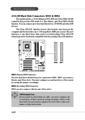
...Slave mode by setting its jumper. IDE2 (Secondary IDE Connector) IDE2 can connect a Master and a Slave drive. MS-6728 ATX Mainboard ATA100 Hard Disk Connectors: IDE1 & IDE2 The mainboard has a 32-bit Enhanced PCI IDE and Ultra DMA 66/100 controller that provides PIO mode 0~4, Bus Master, and Ultra DMA... 66/100 function. MSI Reminds You... IDE1 can also connect a Master and a Slave drive. BATT + IDE2 IDE1 IDE1 (Primary IDE ...
...Slave mode by setting its jumper. IDE2 (Secondary IDE Connector) IDE2 can connect a Master and a Slave drive. MS-6728 ATX Mainboard ATA100 Hard Disk Connectors: IDE1 & IDE2 The mainboard has a 32-bit Enhanced PCI IDE and Ultra DMA 66/100 controller that provides PIO mode 0~4, Bus Master, and Ultra DMA... 66/100 function. MSI Reminds You... IDE1 can also connect a Master and a Slave drive. BATT + IDE2 IDE1 IDE1 (Primary IDE ...
User Guide
Page 41
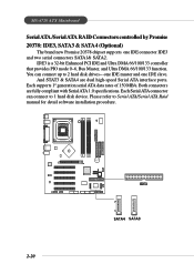
... 1 hard disk device. Please refer to 2 hard disk drives---one IDE master and one IDE connector IDE3 and two serial connectors SATA1& SATA2. MS-6728 ATX Mainboard Serial ATA /Serial ATA RAID Connectors controlled by Promise 20378: IDE3, SATA3 & SATA4 (Optional) The brand new Promise 20378 chipset supports one IDE slave. Each...
... 1 hard disk device. Please refer to 2 hard disk drives---one IDE master and one IDE connector IDE3 and two serial connectors SATA1& SATA2. MS-6728 ATX Mainboard Serial ATA /Serial ATA RAID Connectors controlled by Promise 20378: IDE3, SATA3 & SATA4 (Optional) The brand new Promise 20378 chipset supports one IDE slave. Each...
User Guide
Page 43
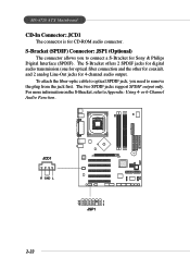
... to connect a S-Bracket for Sony & Philips Digital Interface (SPDIF). To attach the fiber-optic cable to optical SPDIF jack, you to Appendix: Using 4- MS-6728 ATX Mainboard CD-In Connector: JCD1 The connector is for 4-channel audio output.
... to connect a S-Bracket for Sony & Philips Digital Interface (SPDIF). To attach the fiber-optic cable to optical SPDIF jack, you to Appendix: Using 4- MS-6728 ATX Mainboard CD-In Connector: JCD1 The connector is for 4-channel audio output.
User Guide
Page 45
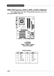
B ATT + 9 1 10 2 J1394_1, J1394_2, J1394_3 (from left to connect optional IEEE 1394 ports. MS-6728 ATX Mainboard IEEE 1394 Connectors: J1394_1, J1394_2, J1394_3 (Optional) The mainboard provides three 1394 pin headers that allow you to right) J1394 Pin Definition PIN SIGNAL PIN 1 TPA+ 2 3 Ground 4 5 TPB+ 6 7 Cable power 8 9 Key (no pin) 10 SIGNAL TPAGround TPBCable power Ground 2-24
B ATT + 9 1 10 2 J1394_1, J1394_2, J1394_3 (from left to connect optional IEEE 1394 ports. MS-6728 ATX Mainboard IEEE 1394 Connectors: J1394_1, J1394_2, J1394_3 (Optional) The mainboard provides three 1394 pin headers that allow you to right) J1394 Pin Definition PIN SIGNAL PIN 1 TPA+ 2 3 Ground 4 5 TPB+ 6 7 Cable power 8 9 Key (no pin) 10 SIGNAL TPAGround TPBCable power Ground 2-24
User Guide
Page 47
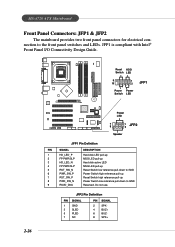
...-down to the front panel switches and LEDs. JFP2 Pin Definition PIN SIGNAL 1 GND 3 SLED 5 PLED 7 NC PIN SIGNAL 2 SPK- 4 BUZ+ 6 BUZ- 8 SPK+ MS-6728 ATX Mainboard Front Panel Connectors: JFP1 & JFP2 The mainboard provides two front panel connectors for electrical connection to GND Reserved.
...-down to the front panel switches and LEDs. JFP2 Pin Definition PIN SIGNAL 1 GND 3 SLED 5 PLED 7 NC PIN SIGNAL 2 SPK- 4 BUZ+ 6 BUZ- 8 SPK+ MS-6728 ATX Mainboard Front Panel Connectors: JFP1 & JFP2 The mainboard provides two front panel connectors for electrical connection to GND Reserved.


