User Guide
Page 2
...trademarks or trademarks of NVIDIA Corporation in the United States and/or other information: http://global.msi.com.tw/index.php? AMI® is a registered trademark of Novell, Inc. Revision ...be obtained from the user's manual, please contact your place of Intel Corporation. Visit the MSI website for further guidance. NVIDIA, the NVIDIA logo, DualNet, and nForce are registered trademarks ...trademarks of purchase or local distributor. func=service Contact our technical staff at: http://ocss.msi.com.tw ii W indows® NT/XP/Vista are under continual improvement and we ...
...trademarks or trademarks of NVIDIA Corporation in the United States and/or other information: http://global.msi.com.tw/index.php? AMI® is a registered trademark of Novell, Inc. Revision ...be obtained from the user's manual, please contact your place of Intel Corporation. Visit the MSI website for further guidance. NVIDIA, the NVIDIA logo, DualNet, and nForce are registered trademarks ...trademarks of purchase or local distributor. func=service Contact our technical staff at: http://ocss.msi.com.tw ii W indows® NT/XP/Vista are under continual improvement and we ...
User Guide
Page 8
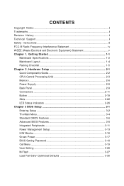
... ...2-8 Back Panel ...2-9 Connectors ...2-11 Button ...2-19 Slots ...2-22 LED Status Indicators 2-26 Chapter 3 BIOS Setup 3-1 Entering Setup ...3-2 The Main Menu ...3-4 Standard CMOS Features 3-6 Advanced BIOS Features 3-8 Integrated Peripherals 3-11 Power Management Setup 3-13 H/W Monitor ...3-16 Green Power ...3-17 BIOS Setting Password 3-18 Cell Menu ...3-19 User Setting ...3-26 M-Flash ...3-27 Load Fail-Safe...
... ...2-8 Back Panel ...2-9 Connectors ...2-11 Button ...2-19 Slots ...2-22 LED Status Indicators 2-26 Chapter 3 BIOS Setup 3-1 Entering Setup ...3-2 The Main Menu ...3-4 Standard CMOS Features 3-6 Advanced BIOS Features 3-8 Integrated Peripherals 3-11 Power Management Setup 3-13 H/W Monitor ...3-16 Green Power ...3-17 BIOS Setting Password 3-18 Cell Menu ...3-19 User Setting ...3-26 M-Flash ...3-27 Load Fail-Safe...
User Guide
Page 26
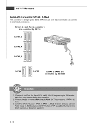
... connectors are controlled by SB750 SATA1_2 SATA3_4 SATA5_6 SATA8 SATA7 SATA7 & SATA8 are controlled by JMB322 Important 1. Each connector can set RAID mode in BIOS setup or in DRIVE BOOSTER MANAGER (refer to one Serial ATA device. SATA7 & SATA8 support RAID 0/ RAID 1/ JBOD function and you can... connect to the BIOS section or Appendix section). 2-12 MS-7577 Mainboard Serial ATA Connector: SATA1~ SATA8 This connector is a high-speed Serial ATA interface port. Please...
... connectors are controlled by SB750 SATA1_2 SATA3_4 SATA5_6 SATA8 SATA7 SATA7 & SATA8 are controlled by JMB322 Important 1. Each connector can set RAID mode in BIOS setup or in DRIVE BOOSTER MANAGER (refer to one Serial ATA device. SATA7 & SATA8 support RAID 0/ RAID 1/ JBOD function and you can... connect to the BIOS section or Appendix section). 2-12 MS-7577 Mainboard Serial ATA Connector: SATA1~ SATA8 This connector is a high-speed Serial ATA interface port. Please...
User Guide
Page 27
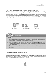
...'s official website or consult the vendors for CPUFAN1. Chassis Intrusion Connector: JCI1 This connector connects to GND. To clear the warning, you must enter the BIOS utility and clear the record. Hardware Setup Fan Power Connectors: CPUFAN1, SYSFAN1/ 2/ 3/ 4 The fan power connectors support system cooling fan with 3 or 4 pins power connector...
...'s official website or consult the vendors for CPUFAN1. Chassis Intrusion Connector: JCI1 This connector connects to GND. To clear the warning, you must enter the BIOS utility and clear the record. Hardware Setup Fan Power Connectors: CPUFAN1, SYSFAN1/ 2/ 3/ 4 The fan power connectors support system cooling fan with 3 or 4 pins power connector...
User Guide
Page 34
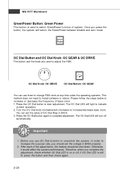
... adjustments, this feature should set the value of system. OC Dial Knob: OC DRIVE OC Dial Button: OC GEAR You can set the voltage in BIOS. 3. Before you should be shut down. MS-7577 Mainboard GreenPower Button: Green Power This button is still lit, press the button and then check ... operation. 2. The OC Dial LED will light to start adjustment. You can use OC Dial function to switch GreenPower function of OC Dial Step in BIOS properly. 2. Therefore, when you press the button, the system will turn off , if OC Dial LED is used to increase the success rate, you use...
... adjustments, this feature should set the value of system. OC Dial Knob: OC DRIVE OC Dial Button: OC GEAR You can set the voltage in BIOS. 3. Before you should be shut down. MS-7577 Mainboard GreenPower Button: Green Power This button is still lit, press the button and then check ... operation. 2. The OC Dial LED will light to start adjustment. You can use OC Dial function to switch GreenPower function of OC Dial Step in BIOS properly. 2. Therefore, when you press the button, the system will turn off , if OC Dial LED is used to increase the success rate, you use...
User Guide
Page 35
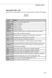
...the table below to OS Loader (typically INT 19H). C4, C6 Initialize chipset. Load Option ROM (VGA and RAID option ROM) form BIOS to memory. 37 Displaying sign-on and first initialize CPU. A7 Display the system configuration screen if enabled. D4, D5 Initialize memory. 08...). AA Enter OS (Vista or W indows XP). 2-21 B1 Save system context for user input at configuration display if needed / requested. BIOS setup if needed . Post Status FF Power on message, CPU information, setup key message and any OEM specific information. 38 Initialize USB device ...
...the table below to OS Loader (typically INT 19H). C4, C6 Initialize chipset. Load Option ROM (VGA and RAID option ROM) form BIOS to memory. 37 Displaying sign-on and first initialize CPU. A7 Display the system configuration screen if enabled. D4, D5 Initialize memory. 08...). AA Enter OS (Vista or W indows XP). 2-21 B1 Save system context for user input at configuration display if needed / requested. BIOS setup if needed . Post Status FF Power on message, CPU information, setup key message and any OEM specific information. 38 Initialize USB device ...
User Guide
Page 36
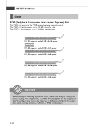
... rate. The PCIE x1 slot supports up to 250 MB/s transfer rate. Meanwhile, read the documentation for the expansion card, such as jumpers, switches or BIOS configuration. 2-22 PCI_E1 supports up to PCIE 2.0 x16 speed PCI_E2 supports up to PCIE 2.0 x1 speed PCI_E3 supports up to PCIE 2.0 x8 speed PCI_E4 supports...
... rate. The PCIE x1 slot supports up to 250 MB/s transfer rate. Meanwhile, read the documentation for the expansion card, such as jumpers, switches or BIOS configuration. 2-22 PCI_E1 supports up to PCIE 2.0 x16 speed PCI_E2 supports up to PCIE 2.0 x1 speed PCI_E3 supports up to PCIE 2.0 x8 speed PCI_E4 supports...
User Guide
Page 37
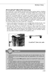
... system's graphics capabilities. Please note that although you connect an adequate power supply to the power connector on PCIE_E1 & PCI_E4 slots. 3. Motherboard photos shown in BIOS by yourself. these graphics cards are for CrossFireXTM mode, make sure that you have to enable the CrossFireXTM in this the most scalable gaming platform...
... system's graphics capabilities. Please note that although you connect an adequate power supply to the power connector on PCIE_E1 & PCI_E4 slots. 3. Motherboard photos shown in BIOS by yourself. these graphics cards are for CrossFireXTM mode, make sure that you have to enable the CrossFireXTM in this the most scalable gaming platform...
User Guide
Page 39
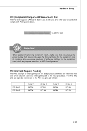
PCI Interrupt Request Routing The IRQ, acronym of interrupt request line and pronounced I-R-Q, are typically connected to the PCI bus pins as jumpers, switches or BIOS configuration. The PCI IRQ pins are hardware lines over which devices can send interrupt signals to configure any necessary hardware or software settings for the ...
PCI Interrupt Request Routing The IRQ, acronym of interrupt request line and pronounced I-R-Q, are typically connected to the PCI bus pins as jumpers, switches or BIOS configuration. The PCI IRQ pins are hardware lines over which devices can send interrupt signals to configure any necessary hardware or software settings for the ...

User Guide
Page 42
You may need to run the Setup program when: ² An error message appears on the BIOS Setup program and allows you to run SETUP. ² You want to configure the system for customized features. 3-1 Chapter 3 BIOS Setup BIOS Setup This chapter provides information on the screen during the system booting up, and requests you to change the default settings for optimum use.
You may need to run the Setup program when: ² An error message appears on the BIOS Setup program and allows you to run SETUP. ² You want to configure the system for customized features. 3-1 Chapter 3 BIOS Setup BIOS Setup This chapter provides information on the screen during the system booting up, and requests you to change the default settings for optimum use.

User Guide
Page 43
... described in the format: A7577AMS V1.0 010109 where: 1st digit refers to BIOS maker as A = AMI, W = AWARD, and P = PHOENIX. 2nd - 5th digit refers to the model number. 6th digit refers to the ... start POST (Power On Self Test) process. You may be slightly different from the latest BIOS and should be held for better system performance. Upon boot-up, the 1st line appearing after the memory count ...-7577 Mainboard Entering Setup Power on the screen, press key to enter Setup. It is the BIOS version. Important 1. Press DEL to enter SETUP If the message disappears before you respond and you...
... described in the format: A7577AMS V1.0 010109 where: 1st digit refers to BIOS maker as A = AMI, W = AWARD, and P = PHOENIX. 2nd - 5th digit refers to the model number. 6th digit refers to the ... start POST (Power On Self Test) process. You may be slightly different from the latest BIOS and should be held for better system performance. Upon boot-up, the 1st line appearing after the memory count ...-7577 Mainboard Entering Setup Power on the screen, press key to enter Setup. It is the BIOS version. Important 1. Press DEL to enter SETUP If the message disappears before you respond and you...

User Guide
Page 44
General Help The BIOS setup program provides a General Help screen. You can use and the possible selections for a field parameter. Sub-M enu If you can use arrow keys ( ↑&#.... If you will see is displayed at the bottom of the screen. The on-line description of the highlighted setup function is the Main Menu. BIOS Setup Control Keys Enter> Move to the previous item Move to the next item Move to the item in the left hand Move to the...
General Help The BIOS setup program provides a General Help screen. You can use and the possible selections for a field parameter. Sub-M enu If you can use arrow keys ( ↑&#.... If you will see is displayed at the bottom of the screen. The on-line description of the highlighted setup function is the Main Menu. BIOS Setup Control Keys Enter> Move to the previous item Move to the next item Move to the item in the left hand Move to the...
User Guide
Page 45
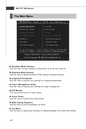
... for integrated peripherals. Integrated Peripherals Use this menu for frequency/voltage control and overclocking. 3-4 BIOS Setting Password Use this menu to setup the items of AMI® special enhanced features. Advanced BIOS Features Use this menu to specify your settings for basic system configurations, such as time,... etc. Power Management Setup Use this menu to set the password for power management. H/W Monitor This entry shows your settings for BIOS. Cell Menu Use this menu to specify the power phase. Green Power Use this menu to specify your PC health status.
... for integrated peripherals. Integrated Peripherals Use this menu for frequency/voltage control and overclocking. 3-4 BIOS Setting Password Use this menu to setup the items of AMI® special enhanced features. Advanced BIOS Features Use this menu to specify your settings for basic system configurations, such as time,... etc. Power Management Setup Use this menu to set the password for power management. H/W Monitor This entry shows your settings for BIOS. Cell Menu Use this menu to specify the power phase. Green Power Use this menu to specify your PC health status.
User Guide
Page 46
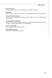
Load Optimized Defaults Use this menu to load the default values set by the motherboard manufacturer specifically for stable system performance. Save & Exit Setup Save changes to read/ flash the BIOS from CMOS for BIOS. Load Fail-Safe Defaults Use this menu to load the default values set by the BIOS vendor for optimal performance of the motherboard. BIOS Setup User Settings Use this menu to save/ load your settings to/ from storage drive (FAT/ FAT32 format only). Exit Without Saving Abandon all changes and exit setup. 3-5 M-Flash Use this menu to CMOS and exit setup.
Load Optimized Defaults Use this menu to load the default values set by the motherboard manufacturer specifically for stable system performance. Save & Exit Setup Save changes to read/ flash the BIOS from CMOS for BIOS. Load Fail-Safe Defaults Use this menu to load the default values set by the BIOS vendor for optimal performance of the motherboard. BIOS Setup User Settings Use this menu to save/ load your settings to/ from storage drive (FAT/ FAT32 format only). Exit Without Saving Abandon all changes and exit setup. 3-5 M-Flash Use this menu to CMOS and exit setup.
User Guide
Page 47
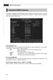
..., from Jan. through Dec. year The year can be adjusted by numeric function keys. Date (MM:DD:YY) This allows you to Sat, determined by BIOS. month The month from Sun to set the system time that you want (usually the current time). date The date from 1 to enter the sub...
..., from Jan. through Dec. year The year can be adjusted by numeric function keys. Date (MM:DD:YY) This allows you to Sat, determined by BIOS. month The month from Sun to set the system time that you want (usually the current time). date The date from 1 to enter the sub...
User Guide
Page 48
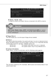
... system doesn't stop for the errors preset, it will stop if an error is detected. This sub-menu shows the CPU information, BIOS version and memory status of floppy drives installed. Hold on The setting determines whether the system will halt on the motherboard. System Information Press... to the IDE/ SATA/ ESATA connector on for 15 seconds and then automatically resume its operation. BIOS Setup Device / Vender / Size It shows the device information that you connected to set the type of your system (read only). 3-7 W ...
... system doesn't stop for the errors preset, it will stop if an error is detected. This sub-menu shows the CPU information, BIOS version and memory status of floppy drives installed. Hold on The setting determines whether the system will halt on the motherboard. System Information Press... to the IDE/ SATA/ ESATA connector on for 15 seconds and then automatically resume its operation. BIOS Setup Device / Vender / Size It shows the device information that you connected to set the type of your system (read only). 3-7 W ...
User Guide
Page 49
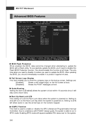
... screen. Enabling APIC mode will allow users to enable or disable the APIC (Advanced Programmable Interrupt Controller). MS-7577 Mainboard Advanced BIOS Features BIOS Flash Protection W hen enabled, the BIOS' data cannot be changed when attempting to [On] will turn on the Num Lock key when the system is powered on.... is used to use the arrow keys on the full screen at boot. [Disabled] Shows the POST messages at all times. After updating the BIOS, you want to disable this function at boot. Due to compliance with a Flash utility. The only time when you 'll need to disable ...
... screen. Enabling APIC mode will allow users to enable or disable the APIC (Advanced Programmable Interrupt Controller). MS-7577 Mainboard Advanced BIOS Features BIOS Flash Protection W hen enabled, the BIOS' data cannot be changed when attempting to [On] will turn on the Num Lock key when the system is powered on.... is used to use the arrow keys on the full screen at boot. [Disabled] Shows the POST messages at all times. After updating the BIOS, you want to disable this function at boot. Due to compliance with a Flash utility. The only time when you 'll need to disable ...
User Guide
Page 50
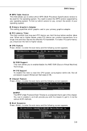
... set to higher values, every PCI device can conduct transactions for the operating system. Chipset Feature Press to read the CPU power consumption while idle. BIOS Setup MPS Table Version This field allows you with the means to get to it , and will provide you to select which graphic card is...
... set to higher values, every PCI device can conduct transactions for the operating system. Chipset Feature Press to read the CPU power consumption while idle. BIOS Setup MPS Table Version This field allows you with the means to get to it , and will provide you to select which graphic card is...
User Guide
Page 51
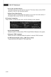
... the disk operating system. MS-7577 Mainboard 1st/ 2nd/ 3rd Boot Device The items allow you to set the first/ second/ Third boot device where BIOS attempts to the system. Execute TPM Command Setting the option to [Enable] allows the system to boot from other device. if the system fails to...
... the disk operating system. MS-7577 Mainboard 1st/ 2nd/ 3rd Boot Device The items allow you to set the first/ second/ Third boot device where BIOS attempts to the system. Execute TPM Command Setting the option to [Enable] allows the system to boot from other device. if the system fails to...
User Guide
Page 52
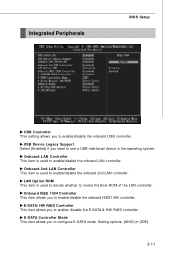
... invoke the Boot ROM of the LAN controller. USB Device Legacy Support Select [Enabled] if you to enable/disable the onboard USB controller. Integrated Peripherals BIOS Setup USB Controller This setting allows you to enable/disable the onboard IEEE1394 controller. Setting options: [AHCI] or [IDE]. 3-11
... invoke the Boot ROM of the LAN controller. USB Device Legacy Support Select [Enabled] if you to enable/disable the onboard USB controller. Integrated Peripherals BIOS Setup USB Controller This setting allows you to enable/disable the onboard IEEE1394 controller. Setting options: [AHCI] or [IDE]. 3-11


