User Guide
Page 8
Hardware Setup 2-1 Quick Components Guide 2-2 CPU (Central Processing Unit 2-3 Memory ...2-6 Power Supply ...2-8 Back Panel ...2-9 Connectors ...2-11 Button ...2-19 Slots ...2-22 LED Status Indicators 2-26 Chapter 3 BIOS Setup 3-1 Entering Setup ...3-2 The Main Menu ...3-4 Standard CMOS Features 3-6 ...
Hardware Setup 2-1 Quick Components Guide 2-2 CPU (Central Processing Unit 2-3 Memory ...2-6 Power Supply ...2-8 Back Panel ...2-9 Connectors ...2-11 Button ...2-19 Slots ...2-22 LED Status Indicators 2-26 Chapter 3 BIOS Setup 3-1 Entering Setup ...3-2 The Main Menu ...3-4 Standard CMOS Features 3-6 ...
User Guide
Page 11
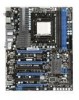
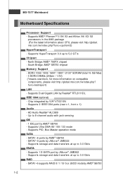
...174; 790FX chipset - South Bridge: AMD® SB750 chipset Memory Support - HD Audio Realtek® ALC889 - Supports storage and data transfers at up to 3.0 Gb/s ESATA - MS-7577 Mainboard Motherboard Specifications ...Processor Support - DDR3 1066/ 1333/ 1600*/ 1800*/ 2133* SDRAM (total 16 GB Max) - 4 DDR3 DIMMs (240pin / 1.5V) (*means overclock, for more information on compatible components, please visit http://global.msi...
...174; 790FX chipset - South Bridge: AMD® SB750 chipset Memory Support - HD Audio Realtek® ALC889 - Supports storage and data transfers at up to 3.0 Gb/s ESATA - MS-7577 Mainboard Motherboard Specifications ...Processor Support - DDR3 1066/ 1333/ 1600*/ 1800*/ 2133* SDRAM (total 16 GB Max) - 4 DDR3 DIMMs (240pin / 1.5V) (*means overclock, for more information on compatible components, please visit http://global.msi...

User Guide
Page 20
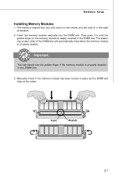
...the DIM M1 first. 2-6 You should always install DDR3 memory modules in different channel DIMM slots. - For more information on compatible components, please visit http://global.msi.com. In Dual-Channel mode, make sure that you install memory modules of the same type and density in the DDR3... DIMM slots. - MS-7577 Mainboard Memory These DIMM slots are not interchangeable with two data bus lines...
...the DIM M1 first. 2-6 You should always install DDR3 memory modules in different channel DIMM slots. - For more information on compatible components, please visit http://global.msi.com. In Dual-Channel mode, make sure that you install memory modules of the same type and density in the DDR3... DIMM slots. - MS-7577 Mainboard Memory These DIMM slots are not interchangeable with two data bus lines...
User Guide
Page 21
... vertically into the DIMM slot. Volt Notch 2-7 The memory module has only one notch on the memory module is properly inserted in place by the DIMM slot clips at each side of the DIMM slot will only fit in the DIMM slot. ...The plastic clip at the sides. Important You can barely see the golden finger if the memory module is deeply inserted in the right orientation. 2. Manually check if the memory module has been locked in the DIMM slot. 3. Then push it in until the golden finger on the center...
... vertically into the DIMM slot. Volt Notch 2-7 The memory module has only one notch on the memory module is properly inserted in place by the DIMM slot clips at each side of the DIMM slot will only fit in the DIMM slot. ...The plastic clip at the sides. Important You can barely see the golden finger if the memory module is deeply inserted in the right orientation. 2. Manually check if the memory module has been locked in the DIMM slot. 3. Then push it in until the golden finger on the center...
User Guide
Page 35
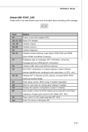
...Display the system configuration screen if enabled. AA Enter OS (Vista or W indows XP). 2-21 C4, C6 Initialize chipset. D4, D5 Initialize memory. 08 Initialize keyboard. 2A, 31 Initialize onboard devices. Detect different devices (parallel ports, serial ports and coprocessor in CPU...etc.) 75, 78...context for user input at configuration display if needed / requested. Load Option ROM (VGA and RAID option ROM) form BIOS to memory. 37 Displaying sign-on and first initialize CPU. A4 W ait for ACPI (Advanced Configuration and Power Interface). C0, C1, C2 Early CPU...
...Display the system configuration screen if enabled. AA Enter OS (Vista or W indows XP). 2-21 C4, C6 Initialize chipset. D4, D5 Initialize memory. 08 Initialize keyboard. 2A, 31 Initialize onboard devices. Detect different devices (parallel ports, serial ports and coprocessor in CPU...etc.) 75, 78...context for user input at configuration display if needed / requested. Load Option ROM (VGA and RAID option ROM) form BIOS to memory. 37 Displaying sign-on and first initialize CPU. A4 W ait for ACPI (Advanced Configuration and Power Interface). C0, C1, C2 Early CPU...

User Guide
Page 40
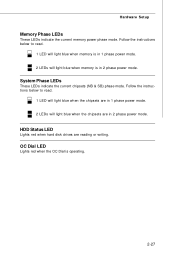
CPU Phase LEDs These LEDs indicate the current CPU power phase mode. MS-7577 Mainboard LED Status Indicators NB Phase LED CPU Phase LEDs Memory Phase LEDs System Phase LEDs OC Dial LED HDD Status LED NB Phase LED Lights blue when the the NB is in 4 phase power mode. 2-26 Follow the instructions below to read. 1 LED will light blue when CPU is in 1 phase power mode. 2 LEDs will light blue when CPU is in 2 phase power mode. 3 LEDs will light blue when CPU is in 3 phase power mode. 4 LEDs will light blue when CPU is operating.
CPU Phase LEDs These LEDs indicate the current CPU power phase mode. MS-7577 Mainboard LED Status Indicators NB Phase LED CPU Phase LEDs Memory Phase LEDs System Phase LEDs OC Dial LED HDD Status LED NB Phase LED Lights blue when the the NB is in 4 phase power mode. 2-26 Follow the instructions below to read. 1 LED will light blue when CPU is in 1 phase power mode. 2 LEDs will light blue when CPU is in 2 phase power mode. 3 LEDs will light blue when CPU is in 3 phase power mode. 4 LEDs will light blue when CPU is operating.
User Guide
Page 41
... operating. 2-27 HDD Status LED Lights red when hard disk drives are in 1 phase power mode. 2 LEDs will light blue when memory is in 2 phase power mode. OC Dial LED Lights red when the OC Dial is in 1 phase power mode. 2 LEDs will light blue when the ...chipsets are in 2 phase power mode. Hardware Setup Memory Phase LEDs These LEDs indicate the current memory power phase mode. System Phase LEDs These LEDs indicate the current chipsets (NB & SB) phase mode. Follow the instructions below to read...
... operating. 2-27 HDD Status LED Lights red when hard disk drives are in 1 phase power mode. 2 LEDs will light blue when memory is in 2 phase power mode. OC Dial LED Lights red when the OC Dial is in 1 phase power mode. 2 LEDs will light blue when the ...chipsets are in 2 phase power mode. Hardware Setup Memory Phase LEDs These LEDs indicate the current memory power phase mode. System Phase LEDs These LEDs indicate the current chipsets (NB & SB) phase mode. Follow the instructions below to read...

User Guide
Page 43
... may be slightly different from the latest BIOS and should be held for better system performance. Upon boot-up, the 1st line appearing after the memory count is usually in this BIOS was released. 3-2 Therefore, the description may also restart the system by turning it OFF and On or pressing the...
... may be slightly different from the latest BIOS and should be held for better system performance. Upon boot-up, the 1st line appearing after the memory count is usually in this BIOS was released. 3-2 Therefore, the description may also restart the system by turning it OFF and On or pressing the...
User Guide
Page 48
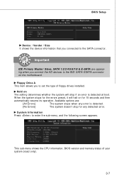
System Information Press to the SATA connector. This sub-menu shows the CPU information, BIOS version and memory status of floppy drives installed. W hen the system stops for the errors preset, it will stop for 15 seconds and then automatically resume ... the IDE/ SATA/ ESATA connector on for any error is detected at boot. Hold on The setting determines whether the system will halt on the motherboard. Important IDE Primary Master/ Slave, SATA 1/2/3/4/5/6/7/8 & E-SATA are : [All Errors] [No Errors] The system stops when any detected error. Available options are ...
System Information Press to the SATA connector. This sub-menu shows the CPU information, BIOS version and memory status of floppy drives installed. W hen the system stops for the errors preset, it will stop for 15 seconds and then automatically resume ... the IDE/ SATA/ ESATA connector on for any error is detected at boot. Hold on The setting determines whether the system will halt on the motherboard. Important IDE Primary Master/ Slave, SATA 1/2/3/4/5/6/7/8 & E-SATA are : [All Errors] [No Errors] The system stops when any detected error. Available options are ...
User Guide
Page 54
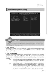
If your operating system is saved to main memory that remains powered while most other hardware components turn off to restore the system when a "wake up" event occurs. 3-13 In this state, no system ... hardware maintains all system context. [S3] The S3 sleep mode is a lower power state where the in formation of this field. The information stored in memory will be used to save energy. ACPI Function This item is a low power state. ACPI Standby State This item specifies the power saving modes for...
If your operating system is saved to main memory that remains powered while most other hardware components turn off to restore the system when a "wake up" event occurs. 3-13 In this state, no system ... hardware maintains all system context. [S3] The S3 sleep mode is a lower power state where the in formation of this field. The information stored in memory will be used to save energy. ACPI Function This item is a low power state. ACPI Standby State This item specifies the power saving modes for...
User Guide
Page 58
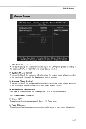
Motherboard LED Control This item is used to reach the best power saving function. Green Power BIOS Setup CPU PWM Phase Control W hen set to [Auto], ... loading of the system. GreenPower Genie----ICore/ I12V These items show the power consumption & efficiency of memory to reach the best power saving function. Pout/ Efficiency These items show the amperage of the motherboard. ----- Read only. 3-17 Memory Phase Control W hen set to [Auto], the hardware will auto adjust the CPU power phase...
Motherboard LED Control This item is used to reach the best power saving function. Green Power BIOS Setup CPU PWM Phase Control W hen set to [Auto], ... loading of the system. GreenPower Genie----ICore/ I12V These items show the power consumption & efficiency of memory to reach the best power saving function. Pout/ Efficiency These items show the amperage of the motherboard. ----- Read only. 3-17 Memory Phase Control W hen set to [Auto], the hardware will auto adjust the CPU power phase...
User Guide
Page 59
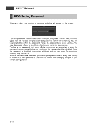
... previously set password from changing any password. A message will show up to six characters in length, and press . This prevents an unauthorized person from CMOS memory. Once the password is disabled, the system will boot and you can enter Setup without entering any part of your system configuration. 3-18 To clear...
... previously set password from changing any password. A message will show up to six characters in length, and press . This prevents an unauthorized person from CMOS memory. Once the password is disabled, the system will boot and you can enter Setup without entering any part of your system configuration. 3-18 To clear...
User Guide
Page 60
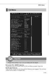
Read-only. This submenu shows the information of CPU and Memory speed. Current CPU / DRAM Frequency These items show the current clocks of installed CPU. 3-19 CPU Specifications Press to enter the sub-menu and the following screen appears. Cell Menu BIOS Setup Important Change these settings only if you are familiar with the chipset.
Read-only. This submenu shows the information of CPU and Memory speed. Current CPU / DRAM Frequency These items show the current clocks of installed CPU. 3-19 CPU Specifications Press to enter the sub-menu and the following screen appears. Cell Menu BIOS Setup Important Change these settings only if you are familiar with the chipset.
User Guide
Page 63
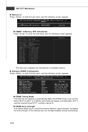
...0], [DCT 1] or [Both], some fields will appear and selectable. DCT 0 controls channel A and DCT1 controls channel B. MS-7577 Mainboard Memory-Z Press to enter the sub-menu and the following screen appears. If you to enter the sub-menu and the following screen appears. DRAM... to enter the sub-menu and the following screen appears. DIMM1~4 Memory SPD Information Press to control the memory data bus' signal strength. Increasing the drive strength of installed memory. This sub-menu displays the informations of the memory bus can increase stability during overclocking. 3-22
...0], [DCT 1] or [Both], some fields will appear and selectable. DCT 0 controls channel A and DCT1 controls channel B. MS-7577 Mainboard Memory-Z Press to enter the sub-menu and the following screen appears. If you to enter the sub-menu and the following screen appears. DRAM... to enter the sub-menu and the following screen appears. DIMM1~4 Memory SPD Information Press to control the memory data bus' signal strength. Increasing the drive strength of installed memory. This sub-menu displays the informations of the memory bus can increase stability during overclocking. 3-22
User Guide
Page 64
...sub-menu and the following screen appears. Setting to [DCT 0], [DCT 1] or [Both], some fields will appear and selectable. 1T/2T Memory Timing This field controls the SDRAM command rate. Auto Disable PCI Frequency W hen set this field to [Auto], the system will automatically reduce the... Frequency (MHz) This field allows you to [Enabled], the system will detect the HT link speed automatically. DCT Unganged Mode This feature is a memory power-saving technology. Setting to [Auto], the system will remove (turn off) clocks from empty PCI slots to Integrate two 64-bit DCTs into ...
...sub-menu and the following screen appears. Setting to [DCT 0], [DCT 1] or [Both], some fields will appear and selectable. 1T/2T Memory Timing This field controls the SDRAM command rate. Auto Disable PCI Frequency W hen set this field to [Auto], the system will automatically reduce the... Frequency (MHz) This field allows you to [Enabled], the system will detect the HT link speed automatically. DCT Unganged Mode This feature is a memory power-saving technology. Setting to [Auto], the system will remove (turn off) clocks from empty PCI slots to Integrate two 64-bit DCTs into ...
User Guide
Page 65
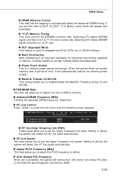
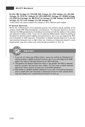
... is reduced, and the system will become less stable. If you are reduced to Enabled for EMI reduction. Spread Spectrum W hen the motherboard's clock generator pulses, the extreme values (spikes) of the pulses create EMI (Electromagnetic Interference). But if you do not have any EMI...optimal system stability and performance. For the most suitable Spread Spectrum value, please consult your overclocked processor to adjust the voltage of CPU, Memory and chipset. But if you are overclocking because even a slight jitter can introduce a temporary boost in clock speed which may just ...
... is reduced, and the system will become less stable. If you are reduced to Enabled for EMI reduction. Spread Spectrum W hen the motherboard's clock generator pulses, the extreme values (spikes) of the pulses create EMI (Electromagnetic Interference). But if you do not have any EMI...optimal system stability and performance. For the most suitable Spread Spectrum value, please consult your overclocked processor to adjust the voltage of CPU, Memory and chipset. But if you are overclocking because even a slight jitter can introduce a temporary boost in clock speed which may just ...
User Guide
Page 94
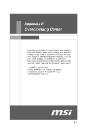
DotNet Frame Work 2.0 B-1 Before you install the Overclocking Center, please make sure the system has meet the following requirements: 1. 256MB system memory. 2. Overclocking Center Appendix B Overclocking Center Overclocking Center, the most useful and powerful utility that MSI has spent much research and efforts to develop, helps users to monitor or configure the hardware status of MSI Motherboard in windows, such as CPU clock, voltage, fan speed and temperature. Operation system: W indows XP or up. 4. DVD-ROM drive for software installation. 3.
DotNet Frame Work 2.0 B-1 Before you install the Overclocking Center, please make sure the system has meet the following requirements: 1. 256MB system memory. 2. Overclocking Center Appendix B Overclocking Center Overclocking Center, the most useful and powerful utility that MSI has spent much research and efforts to develop, helps users to monitor or configure the hardware status of MSI Motherboard in windows, such as CPU clock, voltage, fan speed and temperature. Operation system: W indows XP or up. 4. DVD-ROM drive for software installation. 3.
User Guide
Page 96
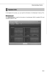
B-3 Overclocking Center System Info In the System Info screen, you can read the information of motherboard/ memory/ PCI. Motherboard Click Motherboard to read the information of motherboard, BIOS, installed CPU and installed graphics card.
B-3 Overclocking Center System Info In the System Info screen, you can read the information of motherboard/ memory/ PCI. Motherboard Click Motherboard to read the information of motherboard, BIOS, installed CPU and installed graphics card.
User Guide
Page 97
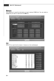
MS-7577 Mainboard Memory Click Memory to read the information of devices on the motherboard. B-4 You can select a DIMM slot you want to read from the SPD list. PCI Click PCI to read the information of each memory DIMM slot.
MS-7577 Mainboard Memory Click Memory to read the information of devices on the motherboard. B-4 You can select a DIMM slot you want to read from the SPD list. PCI Click PCI to read the information of each memory DIMM slot.


