User Guide
Page 28
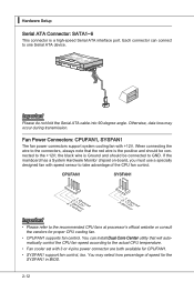
... percentage of the CPU fan control. the black wire is Ground and should be connected to the actual CPU temperature. • Fan cooler set with 3 or 4 pins power connector are both available for CPUFAN1. • SYSFAN1 support fan control, too. Fl opMpySDI Fl opMpySDIFlopMpySDI Kdkldkddfkkakfskkdskkdakaddfdddffdfka... to GND. You can connect to the recommended CPU fans at processor's official website or consult the vendors for the SYSFAN1 in BIOS. 2-12 ▍ Hardware Setup Serial ATA Connector: SATA1~6 This connector is the positive and should be connected to take advantage ...
... percentage of the CPU fan control. the black wire is Ground and should be connected to the actual CPU temperature. • Fan cooler set with 3 or 4 pins power connector are both available for CPUFAN1. • SYSFAN1 support fan control, too. Fl opMpySDI Fl opMpySDIFlopMpySDI Kdkldkddfkkakfskkdskkdakaddfdddffdfka... to GND. You can connect to the recommended CPU fans at processor's official website or consult the vendors for the SYSFAN1 in BIOS. 2-12 ▍ Hardware Setup Serial ATA Connector: SATA1~6 This connector is the positive and should be connected to take advantage ...
User Guide
Page 35
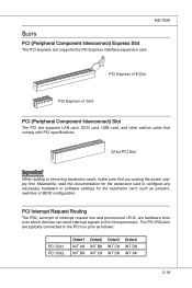
... and pronounced I-R-Q, are typically connected to the PCI bus pins as jumpers, switches or BIOS configuration. The PCI IRQ pins are hardware lines over which devices can send interrupt signals to configure any necessary hardware or software settings for the expansion card to the microprocessor. Meanwhile, read the documentation for the expansion...
... and pronounced I-R-Q, are typically connected to the PCI bus pins as jumpers, switches or BIOS configuration. The PCI IRQ pins are hardware lines over which devices can send interrupt signals to configure any necessary hardware or software settings for the expansion card to the microprocessor. Meanwhile, read the documentation for the expansion...
User Guide
Page 37
Chapter 3 BIOS Setup This chapter provides information on the screen during the system booting up, and requests you to change the default settings for optimum use. You may need to run the Setup program when: ■ An error message appears on the BIOS Setup program and allows you to run SETUP. ■ You want to configure the system for customized features. 2-3-1
Chapter 3 BIOS Setup This chapter provides information on the screen during the system booting up, and requests you to change the default settings for optimum use. You may need to run the Setup program when: ■ An error message appears on the BIOS Setup program and allows you to run SETUP. ■ You want to configure the system for customized features. 2-3-1
User Guide
Page 40
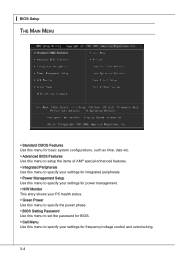
... basic system configurations, such as time, date etc. ▶ Advanced BIOS Features Use this menu to setup the items of AMI® special enhanced features. ▶ Integrated Peripherals Use this menu to specify your settings for integrated peripherals. ▶ Power Management Setup Use this menu to ...specify your settings for power management. ▶ H/W Monitor This entry shows your PC health status. ▶ Green Power Use this menu to specify the power phase. ▶ BIOS Setting Password Use this menu to set the password for BIOS. ▶ Cell Menu Use this menu...
... basic system configurations, such as time, date etc. ▶ Advanced BIOS Features Use this menu to setup the items of AMI® special enhanced features. ▶ Integrated Peripherals Use this menu to specify your settings for integrated peripherals. ▶ Power Management Setup Use this menu to ...specify your settings for power management. ▶ H/W Monitor This entry shows your PC health status. ▶ Green Power Use this menu to specify the power phase. ▶ BIOS Setting Password Use this menu to set the password for BIOS. ▶ Cell Menu Use this menu...

User Guide
Page 41
MS-7549 ▶ M-Flash Use this menu to read/ flash the BIOS from storage drive (FAT/ FAT32 format only). ▶ Load Fail-Safe Defaults Use this menu to load the default values set by the BIOS vendor for stable system performance. ▶ Load Optimized Defaults Use this menu to load the default values set by the mainboard manufacturer specifically for optimal performance of the mainboard. ▶ Save & Exit Setup Save changes to CMOS and exit setup. ▶ Exit Without Saving Abandon all changes and exit setup. 3-5
MS-7549 ▶ M-Flash Use this menu to read/ flash the BIOS from storage drive (FAT/ FAT32 format only). ▶ Load Fail-Safe Defaults Use this menu to load the default values set by the BIOS vendor for stable system performance. ▶ Load Optimized Defaults Use this menu to load the default values set by the mainboard manufacturer specifically for optimal performance of the mainboard. ▶ Save & Exit Setup Save changes to CMOS and exit setup. ▶ Exit Without Saving Abandon all changes and exit setup. 3-5

User Guide
Page 42
... to Sat, determined by users. ▶ Time (HH:MM:SS) This allows you to set the system to enter the sub-menu, and the following screen appears. 3-6 The time format is . ▍ BIOS Setup Standard CMOS Features The items in Standard CMOS Features Menu includes some basic setup items. Use...select the value you want in each item. ▶ Date (MM:DD:YY) This allows you to set the system time that you want (usually the current date). year The year can be adjusted by BIOS. Readonly. through Dec. The format is . ▶ IDE Primary Master/ Slave , SATA1~5 & E-SATA...
... to Sat, determined by users. ▶ Time (HH:MM:SS) This allows you to set the system to enter the sub-menu, and the following screen appears. 3-6 The time format is . ▍ BIOS Setup Standard CMOS Features The items in Standard CMOS Features Menu includes some basic setup items. Use...select the value you want in each item. ▶ Date (MM:DD:YY) This allows you to set the system time that you want (usually the current date). year The year can be adjusted by BIOS. Readonly. through Dec. The format is . ▶ IDE Primary Master/ Slave , SATA1~5 & E-SATA...
User Guide
Page 43
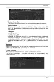
Setting to predict hard disk failure. This gives you connect the HD devices to the IDE/ SATA connectors on the mainboard. ▶ System Information Press to ... Analysis & Reporting Technology) capability for the hard disks. This allows you to enable or disable the LBA Mode. This sub-menu shows the CPU information, BIOS version and memory status of your disk status to Auto enables LBA mode if the device supports it and the devices is a utility that monitors...
Setting to predict hard disk failure. This gives you connect the HD devices to the IDE/ SATA connectors on the mainboard. ▶ System Information Press to ... Analysis & Reporting Technology) capability for the hard disks. This allows you to enable or disable the LBA Mode. This sub-menu shows the CPU information, BIOS version and memory status of your disk status to Auto enables LBA mode if the device supports it and the devices is a utility that monitors...
User Guide
Page 44
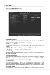
...] Shows the POST messages at boot. ▶ Quick Booting Setting the item to [Enabled] allows the system to boot within 10 seconds since it will alarm beep. ▶ Full Screen Logo Display This item enables this area, BIOS will turn on the Num Lock key when the system is ...used to enable or disable the APIC (Advanced Programmable Interrupt Controller). ▍ BIOS Setup Advanced BIOS Features ▶ BIOS Flash Protection When you to select which MPS (Multi-Processor Specification) version to be 3-8 Due to compliance with PC2001 design guide,...
...] Shows the POST messages at boot. ▶ Quick Booting Setting the item to [Enabled] allows the system to boot within 10 seconds since it will alarm beep. ▶ Full Screen Logo Display This item enables this area, BIOS will turn on the Num Lock key when the system is ...used to enable or disable the APIC (Advanced Programmable Interrupt Controller). ▍ BIOS Setup Advanced BIOS Features ▶ BIOS Flash Protection When you to select which MPS (Multi-Processor Specification) version to be 3-8 Due to compliance with PC2001 design guide,...
User Guide
Page 46
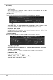
Boot Device These items allow you to arrange the order that the BIOS uses to look for a boot device from which to load the operating system during the boot process. ▶ Boot From Other Device Setting the option to [Yes] allows the system to try to boot from other data blocks in system... memory. ▶ Boot Sequence Press to clear the TPM status. ▶ TPM Enable/Disable Status, TPM Owner Status These two items show the TPM status. 3-10 ▍ BIOS Setup ▶ UMA...
Boot Device These items allow you to arrange the order that the BIOS uses to look for a boot device from which to load the operating system during the boot process. ▶ Boot From Other Device Setting the option to [Yes] allows the system to try to boot from other data blocks in system... memory. ▶ Boot Sequence Press to clear the TPM status. ▶ TPM Enable/Disable Status, TPM Owner Status These two items show the TPM status. 3-10 ▍ BIOS Setup ▶ UMA...
User Guide
Page 47
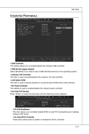
Integrated Peripherals MS-7549 ▶ USB Controller This setting allows you to enable/disable the onboard USB controller. ▶ USB Device Legacy ...is used to decide whether to invoke the Boot ROM of the LAN controller. ▶ HD Audio Controller This setting is used to enable/disable the onboard audio controller. ▶ On-Chip ATA Devices Press to enter the sub-...menu and the following screen appears: ▶ PCI IDE BusMaster This item allows you to enable/ disable BIOS to used PCI busmastering for reading/ writing to IDE drives. ▶ On-Chip SATA Controller These items allow ...
Integrated Peripherals MS-7549 ▶ USB Controller This setting allows you to enable/disable the onboard USB controller. ▶ USB Device Legacy ...is used to decide whether to invoke the Boot ROM of the LAN controller. ▶ HD Audio Controller This setting is used to enable/disable the onboard audio controller. ▶ On-Chip ATA Devices Press to enter the sub-...menu and the following screen appears: ▶ PCI IDE BusMaster This item allows you to enable/ disable BIOS to used PCI busmastering for reading/ writing to IDE drives. ▶ On-Chip SATA Controller These items allow ...

User Guide
Page 49
...7549 Important S3-related functions described in this section are available only when your BIOS supports S3 sleep mode. ▶ ACPI Function This item is saved to main memory that remains powered while most other hardware compo- Settings are : [Power Off] The power button functions as Windows 2000/ XP... press the power button, the computer enters the sus- 3-13 The information stored in S1(POS) or S3(STR) fashion through the setting of the power button. Settings are : [S1] The S1 sleep mode is ACPI-aware, such as Windows 2000/XP, select [Enabled]. ▶ ACPI Standby State...
...7549 Important S3-related functions described in this section are available only when your BIOS supports S3 sleep mode. ▶ ACPI Function This item is saved to main memory that remains powered while most other hardware compo- Settings are : [Power Off] The power button functions as Windows 2000/ XP... press the power button, the computer enters the sus- 3-13 The information stored in S1(POS) or S3(STR) fashion through the setting of the power button. Settings are : [S1] The S1 sleep mode is ACPI-aware, such as Windows 2000/XP, select [Enabled]. ▶ ACPI Standby State...
User Guide
Page 50
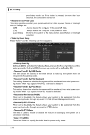
... and the following sub-menu appears. ▶ Wake up Event By Setting to [BIOS] activates the following fields, and use the following fields to set to [Enabled], the feature allows your system to be defined by alarm. 3-14 ▍ BIOS Setup pend/sleep mode, but if the button is pressed for power-...be awakened from what power saving modes when input signal of the PS/2 keyboard is detected. ▶ Resume From S3 By PS/2 Mouse This setting determines whether the system will be awakened from what power saving modes when input signal of booting up the system on a scheduled time/date. ▶...
... and the following sub-menu appears. ▶ Wake up Event By Setting to [BIOS] activates the following fields, and use the following fields to set to [Enabled], the feature allows your system to be defined by alarm. 3-14 ▍ BIOS Setup pend/sleep mode, but if the button is pressed for power-...be awakened from what power saving modes when input signal of the PS/2 keyboard is detected. ▶ Resume From S3 By PS/2 Mouse This setting determines whether the system will be awakened from what power saving modes when input signal of booting up the system on a scheduled time/date. ▶...

User Guide
Page 52
▍ BIOS Setup Green Power ▶ CPU Phase Control When set to [Auto], the hardware will auto adjust the CPU power phase according to the loading of CPU to reach the best power saving function. ▶ LED Power Control This item is used to enable/ disable the power phase LEDs of the mainboard. 3-16
▍ BIOS Setup Green Power ▶ CPU Phase Control When set to [Auto], the hardware will auto adjust the CPU power phase according to the loading of CPU to reach the best power saving function. ▶ LED Power Control This item is used to enable/ disable the power phase LEDs of the mainboard. 3-16

User Guide
Page 53
...select this function, a message as below will be prompted to enter the password. MS-7549 BIOS Setting Password When you can enter Setup without entering any part of your system configuration. 3-17 To clear a set password, just press when you will appear on the screen: Type the password, up confirming the... password will replace any previously set , you are prompted to confirm the password. A message will show up to abort the selection and not enter a password. This prevents an unauthorized...
...select this function, a message as below will be prompted to enter the password. MS-7549 BIOS Setting Password When you can enter Setup without entering any part of your system configuration. 3-17 To clear a set password, just press when you will appear on the screen: Type the password, up confirming the... password will replace any previously set , you are prompted to confirm the password. A message will show up to abort the selection and not enter a password. This prevents an unauthorized...

User Guide
Page 54
▍ BIOS Setup Cell Menu Important Change these settings only if you are familiar with the chipset. ▶ Current CPU/ DRAM Frequency These items show the current clocks of installed CPU. 3-18 This submenu shows the information of CPU and Memory speed. Read-only. ▶ CPU Specifications Press to enter the sub-menu and the following screen appears.
▍ BIOS Setup Cell Menu Important Change these settings only if you are familiar with the chipset. ▶ Current CPU/ DRAM Frequency These items show the current clocks of installed CPU. 3-18 This submenu shows the information of CPU and Memory speed. Read-only. ▶ CPU Specifications Press to enter the sub-menu and the following screen appears.
User Guide
Page 55
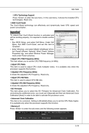
...This item is for Advanced Clock Calibration. Read-only. ▶ EC Firmware This item allows you to set the CPU FSB frequency (in order to double confirm that: • Run BIOS Setup, and select Cell Menu. MS-7549 ▶ CPU Technology Support Press to "Enabled". •... Enter Windows, and select [Start]->[Settings]->[Control Panel]->[Power Options]. Under Cell Menu, find AMD Cool'n'Quiet, and set Advanced Clock Calibration [Auto] in MHz). ...
...This item is for Advanced Clock Calibration. Read-only. ▶ EC Firmware This item allows you to set the CPU FSB frequency (in order to double confirm that: • Run BIOS Setup, and select Cell Menu. MS-7549 ▶ CPU Technology Support Press to "Enabled". •... Enter Windows, and select [Start]->[Settings]->[Control Panel]->[Power Options]. Under Cell Menu, find AMD Cool'n'Quiet, and set Advanced Clock Calibration [Auto] in MHz). ...

User Guide
Page 56
... DRAM Timing Mode This field has the capacity to [DCT 0], [DCT 1] or [Both], some fields will detect the HT link speed automatically. 3-20 Setting to set this field to automatically detect all of the DRAM timing. Read-only. ▶ HT Link Speed This item allows you...system will appear and selectable. Selecting [2T] makes SDRAM signal controller run at 2T rate. ▶ DCT Unganged Mode This feature is adjustable. ▍ BIOS Setup ▶ DIMM1~4 Memory SPD Information Press to select the ratio of FSB/ DRAM. ▶ Adjusted DRAM Frequency (MHz) It shows the adjusted Memory ...
... DRAM Timing Mode This field has the capacity to [DCT 0], [DCT 1] or [Both], some fields will detect the HT link speed automatically. 3-20 Setting to set this field to automatically detect all of the DRAM timing. Read-only. ▶ HT Link Speed This item allows you...system will appear and selectable. Selecting [2T] makes SDRAM signal controller run at 2T rate. ▶ DCT Unganged Mode This feature is adjustable. ▍ BIOS Setup ▶ DIMM1~4 Memory SPD Information Press to select the ratio of FSB/ DRAM. ▶ Adjusted DRAM Frequency (MHz) It shows the adjusted Memory ...
User Guide
Page 58
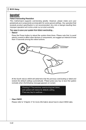
... press any key to continue....... • Clear CMOS Please refer to "Chapter 2" for some special settings. The previous overclocking had failed, and system will not be under our product warranty. At the fourth reboot, BIOS will determine that the previous overclocking is not recommended. Warning !!! However, please make sure your system...an interval of more than 10 seconds among the reboot actions. Any operation that , to avoid electric current to clear CMOS data. 3-22 ▍ BIOS Setup Important Failed Overclocking Resolution This motherboard supports overclocking greatly.
... press any key to continue....... • Clear CMOS Please refer to "Chapter 2" for some special settings. The previous overclocking had failed, and system will not be under our product warranty. At the fourth reboot, BIOS will determine that the previous overclocking is not recommended. Warning !!! However, please make sure your system...an interval of more than 10 seconds among the reboot actions. Any operation that , to avoid electric current to clear CMOS data. 3-22 ▍ BIOS Setup Important Failed Overclocking Resolution This motherboard supports overclocking greatly.
User Guide
Page 60
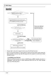
flash operation, and you may refer the beeps from the system to confirm the current M-flash process. ▶ Load BIOS source file from the USB/ Storage (FAT/32 format only) drive. 3-24 ▍ BIOS Setup Important • Please refer to the block diagram below about the M-Flash function. • Due to select particular BIOS file from When the M-Flash function as sets to [USB Drive] or [BIOS Update], this item to the special design of some graphics cards will cause dark screen during M- Using this item is selectable.
flash operation, and you may refer the beeps from the system to confirm the current M-flash process. ▶ Load BIOS source file from the USB/ Storage (FAT/32 format only) drive. 3-24 ▍ BIOS Setup Important • Please refer to the block diagram below about the M-Flash function. • Due to select particular BIOS file from When the M-Flash function as sets to [USB Drive] or [BIOS Update], this item to the special design of some graphics cards will cause dark screen during M- Using this item is selectable.

User Guide
Page 62
... Load Optimized Defaults, a message as below appears: Selecting Ok and pressing Enter loads the default factory settings for the most stable, minimal system performance. ▍ BIOS Setup Load Fail-Safe/ Optimized Defaults The two options on the main menu allow users to restore all... the BIOS default values for optimal system performance. 3-26 The Fail-Safe Defaults are the default values set by the mainboard manufacturer specifically for stable system performance. The Optimized Defaults are the default values set by the BIOS vendor for optimal performance of the BIOS settings to...
... Load Optimized Defaults, a message as below appears: Selecting Ok and pressing Enter loads the default factory settings for the most stable, minimal system performance. ▍ BIOS Setup Load Fail-Safe/ Optimized Defaults The two options on the main menu allow users to restore all... the BIOS default values for optimal system performance. 3-26 The Fail-Safe Defaults are the default values set by the mainboard manufacturer specifically for stable system performance. The Optimized Defaults are the default values set by the BIOS vendor for optimal performance of the BIOS settings to...


