User Guide
Page 2
...and we reserve the right to the correctness of MICRO-STAR INTERNATIONAL. We take every care in this document, but no solution can be obtained from the user's manual, please contact your place of purchase or local ...785GTM-E45 Date July 2009 Technical Support If a problem arises with your system and no guarantee is given as to make changes without notice. Alternatively, please try the following help resources for further guidance. ◙ Visit the MSI website for FAQ, technical guide, BIOS updates, driver updates, and other information: http://www.msi.com/index.php?func=service...
...and we reserve the right to the correctness of MICRO-STAR INTERNATIONAL. We take every care in this document, but no solution can be obtained from the user's manual, please contact your place of purchase or local ...785GTM-E45 Date July 2009 Technical Support If a problem arises with your system and no guarantee is given as to make changes without notice. Alternatively, please try the following help resources for further guidance. ◙ Visit the MSI website for FAQ, technical guide, BIOS updates, driver updates, and other information: http://www.msi.com/index.php?func=service...
User Guide
Page 8
... Started 1-1 Mainboard Specifications 1-2 Mainboard Layout 1-4 Packing Checklist 1-5 Chapter 2 Hardware Setup 2-1 Quick Components Guide 2-2 CPU (Central Processing Unit 2-3 Memory 2-6 Power Supply 2-8 Back Panel 2-9 Connectors 2-11 Jumpers 2-17 Switch 2-18 Slots 2-19 LED Status Indicators 2-20 Chapter 3 BIOS Setup 3-1 Entering Setup 3-2 The Main Menu 3-4 Standard CMOS Features 3-6 Advanced BIOS Features 3-8 Integrated Peripherals 3-11 Power Management Setup 3-13 H/W Monitor 3-15 Green Power 3-16 Cell Menu 3-18 M-Flash 3-23 Load Fail-Safe/ Optimized Defaults 3-26...
... Started 1-1 Mainboard Specifications 1-2 Mainboard Layout 1-4 Packing Checklist 1-5 Chapter 2 Hardware Setup 2-1 Quick Components Guide 2-2 CPU (Central Processing Unit 2-3 Memory 2-6 Power Supply 2-8 Back Panel 2-9 Connectors 2-11 Jumpers 2-17 Switch 2-18 Slots 2-19 LED Status Indicators 2-20 Chapter 3 BIOS Setup 3-1 Entering Setup 3-2 The Main Menu 3-4 Standard CMOS Features 3-6 Advanced BIOS Features 3-8 Integrated Peripherals 3-11 Power Management Setup 3-13 H/W Monitor 3-15 Green Power 3-16 Cell Menu 3-18 M-Flash 3-23 Load Fail-Safe/ Optimized Defaults 3-26...
User Guide
Page 12
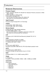
... 8-channel audio with jack sensing ■ Compliant with Azalia 1.0 Spec IDE ■ 1 IDE port by AMD® SB710 ■ Supports Ultra DMA 33/66/100/133, PIO & Bus Master operation mode SATA ■ 6 SATAII ports by AMD® SB710 ■ Supports storage and data transfers at up to 3.0 Gb/s RAID ■ Supports RAID 0/ 1/ 0+1/ JBOD mode by SB710 Floppy ■ 1 floppy port ■ Supports 1 FDD with 360KB, 720KB, 1.2MB, 1.44MB and 2.88MB Connectors ■ Back panel...
... 8-channel audio with jack sensing ■ Compliant with Azalia 1.0 Spec IDE ■ 1 IDE port by AMD® SB710 ■ Supports Ultra DMA 33/66/100/133, PIO & Bus Master operation mode SATA ■ 6 SATAII ports by AMD® SB710 ■ Supports storage and data transfers at up to 3.0 Gb/s RAID ■ Supports RAID 0/ 1/ 0+1/ JBOD mode by SB710 Floppy ■ 1 floppy port ■ Supports 1 FDD with 360KB, 720KB, 1.2MB, 1.44MB and 2.88MB Connectors ■ Back panel...
User Guide
Page 24
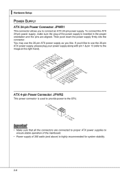
... ATX 4-pin Power Connector: JPWR2 This power connector is used to provide power to the CPU. 2.G1.rGouronudnd 4.+31.+21V2V Important • Make sure that all the connectors are aligned. ▍ Hardware Setup Power Supply ATX 24-pin Power Connector: JPWR1 This connector allows you to ensure stable operation of the mainboard. • Power supply of the power supply is inserted in the proper orientation and the pins are connected to proper ATX power supplies to connect an ATX 24-pin power supply...
... ATX 4-pin Power Connector: JPWR2 This power connector is used to provide power to the CPU. 2.G1.rGouronudnd 4.+31.+21V2V Important • Make sure that all the connectors are aligned. ▍ Hardware Setup Power Supply ATX 24-pin Power Connector: JPWR1 This connector allows you to ensure stable operation of the mainboard. • Power supply of the power supply is inserted in the proper orientation and the pins are connected to proper ATX power supplies to connect an ATX 24-pin power supply...
User Guide
Page 25
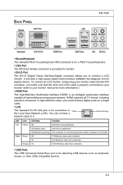
...-Out Line-Out CS-Out Keyboard DVI-D Port HDMI Port USB Ports Mic SS-Out ▶ Mouse/Keyboard The standard PS/2® mouse/keyboard DIN connector is for a PS/2® mouse/keyboard. ▶ VGA Port The DB15-pin female connector is for connection to Yellow the Local Area Network (LAN). It provides a high-speed digital interconnection between the computer and its display device. You can connect a network cable to connect a LCD monitor. The computer is communicating...
...-Out Line-Out CS-Out Keyboard DVI-D Port HDMI Port USB Ports Mic SS-Out ▶ Mouse/Keyboard The standard PS/2® mouse/keyboard DIN connector is for a PS/2® mouse/keyboard. ▶ VGA Port The DB15-pin female connector is for connection to Yellow the Local Area Network (LAN). It provides a high-speed digital interconnection between the computer and its display device. You can connect a network cable to connect a LCD monitor. The computer is communicating...

User Guide
Page 27
... 3 1/2" F loppy Di sk D r ive Connector Important If you install two IDE devices on the same cable, you must configure the drives separately to IDE device's documentation supplied by setting jumpers. Fl opMpySDI Kdkldkddfkkakfskkdskkdakaddfdddffdfkad-dkdffdldkddjadfdsdddjfdddffkadasdfdddffdfadasfsadfddsddadasdsaddsdafsddadsdddfdsadddfffaffsfsdasfdfffdf 5 D 1i s/k4"DFr il voeppCyonnect or 3 1/2" F l oppy D i sk D r i ve Connector 3 1/2" F l oppy D i sk D ri ve Connector IDE Connector: IDE1 This connector supports IDE hard disk drives, optical disk drives and other IDE devices.
... 3 1/2" F loppy Di sk D r ive Connector Important If you install two IDE devices on the same cable, you must configure the drives separately to IDE device's documentation supplied by setting jumpers. Fl opMpySDI Kdkldkddfkkakfskkdskkdakaddfdddffdfkad-dkdffdldkddjadfdsdddjfdddffkadasdfdddffdfadasfsadfddsddadasdsaddsdafsddadsdddfdsadddfffaffsfsdasfdfffdf 5 D 1i s/k4"DFr il voeppCyonnect or 3 1/2" F l oppy D i sk D r i ve Connector 3 1/2" F l oppy D i sk D ri ve Connector IDE Connector: IDE1 This connector supports IDE hard disk drives, optical disk drives and other IDE devices.
User Guide
Page 28
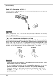
... CPU fan control. You can connect to one Serial ATA device. Fan Power Connectors: CPUFAN1, SYSFAN1 The fan power connectors support system cooling fan with speed sensor to the recommended CPU fans at processor's official website or consult the vendors for CPUFAN1. • SYSFAN1 support fan control, too. the black wire is Ground and should be connected to GND. Each connector can install Dual Core Center utility that the red wire is a high-speed Serial ATA interface port. ▍ Hardware Setup Serial ATA Connector: SATA1~6 This connector...
... CPU fan control. You can connect to one Serial ATA device. Fan Power Connectors: CPUFAN1, SYSFAN1 The fan power connectors support system cooling fan with speed sensor to the recommended CPU fans at processor's official website or consult the vendors for CPUFAN1. • SYSFAN1 support fan control, too. the black wire is Ground and should be connected to GND. Each connector can install Dual Core Center utility that the red wire is a high-speed Serial ATA interface port. ▍ Hardware Setup Serial ATA Connector: SATA1~6 This connector...
User Guide
Page 33
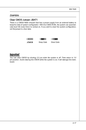
With the CMOS RAM, the system can clear CMOS by shorting 2-3 pin while the system is off. Avoid clearing the CMOS while the system is on . If you want to clear the system configuration, set the jumper to clear data. 1 JCMOS 1 Keep Data 1 Clear Data Important You can automatically boot OS every time it will damage the mainboard. 2-17 MS-7549 Jumpers Clear CMOS Jumper: JBAT1 There is a CMOS RAM onboard that has a power supply from an external battery to 1-2 pin position. it is turned on ; Then return to keep the data of system configuration.
With the CMOS RAM, the system can clear CMOS by shorting 2-3 pin while the system is off. Avoid clearing the CMOS while the system is on . If you want to clear the system configuration, set the jumper to clear data. 1 JCMOS 1 Keep Data 1 Clear Data Important You can automatically boot OS every time it will damage the mainboard. 2-17 MS-7549 Jumpers Clear CMOS Jumper: JBAT1 There is a CMOS RAM onboard that has a power supply from an external battery to 1-2 pin position. it is turned on ; Then return to keep the data of system configuration.
User Guide
Page 35
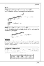
... Slot PCI Express x1 Slot PCI (Peripheral Component Interconnect) Slot The PCI slot supports LAN card, SCSI card, USB card, and other add-on cards that comply with PCI specifications. 32-bit PCI Slot Important When adding or removing expansion cards, make sure that you unplug the power supply first. MS-7549 Slots PCI (Peripheral Component Interconnect) Express Slot The PCI Express slot supports the PCI Express interface expansion card. The PCI IRQ pins are hardware lines over which devices can send interrupt signals to the PCI bus pins as jumpers, switches or BIOS configuration. PCI...
... Slot PCI Express x1 Slot PCI (Peripheral Component Interconnect) Slot The PCI slot supports LAN card, SCSI card, USB card, and other add-on cards that comply with PCI specifications. 32-bit PCI Slot Important When adding or removing expansion cards, make sure that you unplug the power supply first. MS-7549 Slots PCI (Peripheral Component Interconnect) Express Slot The PCI Express slot supports the PCI Express interface expansion card. The PCI IRQ pins are hardware lines over which devices can send interrupt signals to the PCI bus pins as jumpers, switches or BIOS configuration. PCI...
User Guide
Page 43
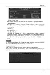
... data from a hard disk that is a utility that you connected to the SATA connector. ▶ LBA/Large Mode This allows you connect the HD devices to the IDE/ SATA connectors on the mainboard. ▶ System Information Press to a safe place before the hard disk becomes offline. Important IDE Primary Master/ Slave , SATA1~5 & E-SATA are appearing when you to activate the S.M.A.R.T. (Self-Monitoring Analysis & Reporting Technology) capability for the hard disks. Setting to predict hard disk failure.
... data from a hard disk that is a utility that you connected to the SATA connector. ▶ LBA/Large Mode This allows you connect the HD devices to the IDE/ SATA connectors on the mainboard. ▶ System Information Press to a safe place before the hard disk becomes offline. Important IDE Primary Master/ Slave , SATA1~5 & E-SATA are appearing when you to activate the S.M.A.R.T. (Self-Monitoring Analysis & Reporting Technology) capability for the hard disks. Setting to predict hard disk failure.
User Guide
Page 44
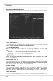
... is powered on. Setting to [On] will allow users to enable or disable the APIC (Advanced Programmable Interrupt Controller). Setting to [Off] will turn on the Num Lock key when the system is able to show the company logo on the boot-up screen. ▍ BIOS Setup Advanced BIOS Features ▶ BIOS Flash Protection When you to select which MPS (Multi-Processor Specification) version to compliance with PC2001 design guide...
... is powered on. Setting to [On] will allow users to enable or disable the APIC (Advanced Programmable Interrupt Controller). Setting to [Off] will turn on the Num Lock key when the system is able to show the company logo on the boot-up screen. ▍ BIOS Setup Advanced BIOS Features ▶ BIOS Flash Protection When you to select which MPS (Multi-Processor Specification) version to compliance with PC2001 design guide...
User Guide
Page 45
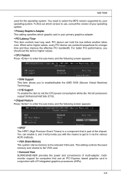
... to enable/disable the AMD SVM (Secure Virtual Machine) Technology. ▶ C1E Support To enable this item to red the CPU power consumption while idle. To find out which version to use an PCI Express based graphics card in conjunction with the means to get to it via the various ACPI methods. ▶ VGA Share Memory The system shares memory to the onboard VGA card. This setting controls the exact memory size shared to the VGA card. ▶...
... to enable/disable the AMD SVM (Secure Virtual Machine) Technology. ▶ C1E Support To enable this item to red the CPU power consumption while idle. To find out which version to use an PCI Express based graphics card in conjunction with the means to get to it via the various ACPI methods. ▶ VGA Share Memory The system shares memory to the onboard VGA card. This setting controls the exact memory size shared to the VGA card. ▶...
User Guide
Page 47
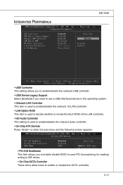
...; Onboard LAN Controller This item is used to enable/disable the onboard 1st LAN controller. ▶ LAN Option ROM This item is used to decide whether to invoke the Boot ROM of the LAN controller. ▶ HD Audio Controller This setting is used to enable/disable the onboard audio controller. ▶ On-Chip ATA Devices Press to enter the sub-menu and the following screen appears: ▶ PCI IDE BusMaster This item allows you to enable/ disable BIOS to used PCI busmastering for reading/ writing to IDE drives. ▶ On-Chip SATA Controller...
...; Onboard LAN Controller This item is used to enable/disable the onboard 1st LAN controller. ▶ LAN Option ROM This item is used to decide whether to invoke the Boot ROM of the LAN controller. ▶ HD Audio Controller This setting is used to enable/disable the onboard audio controller. ▶ On-Chip ATA Devices Press to enter the sub-menu and the following screen appears: ▶ PCI IDE BusMaster This item allows you to enable/ disable BIOS to used PCI busmastering for reading/ writing to IDE drives. ▶ On-Chip SATA Controller...

User Guide
Page 49
..., select [Enabled]. ▶ ACPI Standby State This item specifies the power saving modes for ACPI function. Settings are : [S1] The S1 sleep mode is saved to save energy. Settings are : [Power Off] The power button functions as Windows 2000/ XP , you press the power button, the computer enters the sus- 3-13 In this field. If your operating system supports ACPI, such as normal power off to main memory that remains powered while...
..., select [Enabled]. ▶ ACPI Standby State This item specifies the power saving modes for ACPI function. Settings are : [S1] The S1 sleep mode is saved to save energy. Settings are : [Power Off] The power button functions as Windows 2000/ XP , you press the power button, the computer enters the sus- 3-13 In this field. If your operating system supports ACPI, such as normal power off to main memory that remains powered while...
User Guide
Page 50
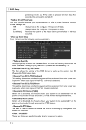
... the USB device to wake up events. ▍ BIOS Setup pend/sleep mode, but if the button is pressed for power-on state. [Last State] Restores the system to the status before power failure or interrupt occurred. ▶ Wake Up Event Setup Press and the following sub-menu appears. ▶ Wake up Event By Setting to [BIOS] activates the following fields, and use the following fields to set the wake...
... the USB device to wake up events. ▍ BIOS Setup pend/sleep mode, but if the button is pressed for power-on state. [Last State] Restores the system to the status before power failure or interrupt occurred. ▶ Wake Up Event Setup Press and the following sub-menu appears. ▶ Wake up Event By Setting to [BIOS] activates the following fields, and use the following fields to set the wake...
User Guide
Page 51
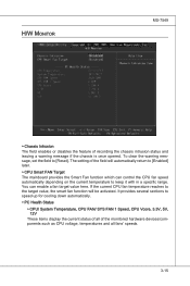
... The mainboard provides the Smart Fan function which can enable a fan target value here. It provides several sections to [Reset]. To clear the warning message, set the field to speed up for cooling down automatically. ▶ PC Health Status ▶ CPU/ System Temperature, CPU FAN/ SYS FAN 1 Speed, CPU Vcore, 3.3V, 5V, 12V These items display the current status of all of the monitored hardware devices/components such as CPU voltage, temperatures...
... The mainboard provides the Smart Fan function which can enable a fan target value here. It provides several sections to [Reset]. To clear the warning message, set the field to speed up for cooling down automatically. ▶ PC Health Status ▶ CPU/ System Temperature, CPU FAN/ SYS FAN 1 Speed, CPU Vcore, 3.3V, 5V, 12V These items display the current status of all of the monitored hardware devices/components such as CPU voltage, temperatures...
User Guide
Page 60
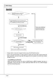
Using this item to select particular BIOS file from When the M-Flash function as sets to [USB Drive] or [BIOS Update], this item is selectable. ▍ BIOS Setup Important • Please refer to the block diagram below about the M-Flash function. • Due to confirm the current M-flash process. ▶ Load BIOS source file from the USB/ Storage (FAT/32 format only) drive. 3-24 flash operation, and you may refer the beeps from the system to the special design of some graphics cards will cause dark screen during M-
Using this item to select particular BIOS file from When the M-Flash function as sets to [USB Drive] or [BIOS Update], this item is selectable. ▍ BIOS Setup Important • Please refer to the block diagram below about the M-Flash function. • Due to confirm the current M-flash process. ▶ Load BIOS source file from the USB/ Storage (FAT/32 format only) drive. 3-24 flash operation, and you may refer the beeps from the system to the special design of some graphics cards will cause dark screen during M-
User Guide
Page 92
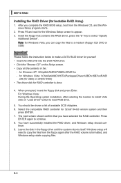
... load RAID drive. 5. tinue. 9. Note: for yourself. • Insert the MSI DVD into the DVD-ROM drive. • Click the "Browse CD" on "Load Driver" button to continue. 8. Windows setup will need to appear. 3. Insert the floppy that you have successfully installed the RAID driver, and Windows setup should confirm that contains the RAID driver, press the "S" key to make a SATA RAID driver for Windows Vista, you complete the RAID BIOS setup, boot from the floppy again after selecting the location to install...
... load RAID drive. 5. tinue. 9. Note: for yourself. • Insert the MSI DVD into the DVD-ROM drive. • Click the "Browse CD" on "Load Driver" button to continue. 8. Windows setup will need to appear. 3. Insert the floppy that you have successfully installed the RAID driver, and Windows setup should confirm that contains the RAID driver, press the "S" key to make a SATA RAID driver for Windows Vista, you complete the RAID BIOS setup, boot from the floppy again after selecting the location to install...

User Guide
Page 93
The driver will appear. 3. Under the Driver tab, click on AMD chipset drivers by your need. The AMD chipset drivers includes RAID Driver. 4. Insert the MSI DVD into the DVD-ROM drive. 2. B-9 The DVD will auto-run and the setup screen will be automatically installed. MS-7549 Installing the RAID Driver Under Windows (for Non-bootable RAID Array) 1.
The driver will appear. 3. Under the Driver tab, click on AMD chipset drivers by your need. The AMD chipset drivers includes RAID Driver. 4. Insert the MSI DVD into the DVD-ROM drive. 2. B-9 The DVD will auto-run and the setup screen will be automatically installed. MS-7549 Installing the RAID Driver Under Windows (for Non-bootable RAID Array) 1.

User Guide
Page 97
... Main Before using this utility. C-3 MB Click MB button to read current GPU temperature, GPU clock and memory clock of the MSI mainboard would be available. VGA Click VGA button to install with the version 8.26 or newer driver)/ V046 or V060 graphics card can activate the full function of mainboard will show below . Introduction: Click each button appearing above to enter sub-menu to make further configuration or to enable or disable the Dynamic Overclocking Technology...
... Main Before using this utility. C-3 MB Click MB button to read current GPU temperature, GPU clock and memory clock of the MSI mainboard would be available. VGA Click VGA button to install with the version 8.26 or newer driver)/ V046 or V060 graphics card can activate the full function of mainboard will show below . Introduction: Click each button appearing above to enter sub-menu to make further configuration or to enable or disable the Dynamic Overclocking Technology...


