User Guide
Page 2
...V1.7 Revision History For 785GTM-E45 Date July 2009 Technical Support If a problem arises with your system and no guarantee is given as to make changes without notice. Our products are the properties of their respective owners. ■ MSI® is registered trademark of Micro-Star Int'l Co.,...help resources for further guidance. ◙ Visit the MSI website for FAQ, technical guide, BIOS updates, driver updates, and other information: http://www.msi.com/index.php?func=service ◙ Contact our technical staff at: http://ocss.msi.com ii We take every care in this document,...
...V1.7 Revision History For 785GTM-E45 Date July 2009 Technical Support If a problem arises with your system and no guarantee is given as to make changes without notice. Our products are the properties of their respective owners. ■ MSI® is registered trademark of Micro-Star Int'l Co.,...help resources for further guidance. ◙ Visit the MSI website for FAQ, technical guide, BIOS updates, driver updates, and other information: http://www.msi.com/index.php?func=service ◙ Contact our technical staff at: http://ocss.msi.com ii We take every care in this document,...
User Guide
Page 8
... Processing Unit 2-3 Memory 2-6 Power Supply 2-8 Back Panel 2-9 Connectors 2-11 Jumpers 2-17 Switch 2-18 Slots 2-19 LED Status Indicators 2-20 Chapter 3 BIOS Setup 3-1 Entering Setup 3-2 The Main Menu 3-4 Standard CMOS Features 3-6 Advanced BIOS Features 3-8 Integrated Peripherals 3-11 Power Management Setup 3-13 H/W Monitor 3-15 Green Power 3-16 Cell Menu 3-18 M-Flash 3-23 Load Fail...
... Processing Unit 2-3 Memory 2-6 Power Supply 2-8 Back Panel 2-9 Connectors 2-11 Jumpers 2-17 Switch 2-18 Slots 2-19 LED Status Indicators 2-20 Chapter 3 BIOS Setup 3-1 Entering Setup 3-2 The Main Menu 3-4 Standard CMOS Features 3-6 Advanced BIOS Features 3-8 Integrated Peripherals 3-11 Power Management Setup 3-13 H/W Monitor 3-15 Green Power 3-16 Cell Menu 3-18 M-Flash 3-23 Load Fail...
User Guide
Page 28
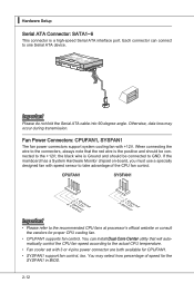
the black wire is Ground and should be connected to take advantage of speed for the SYSFAN1 in BIOS. 2-12 If the mainboard has a System Hardware Monitor chipset on-board, you must use a specially designed fan with speed sensor to GND. Otherwise, data loss ...
the black wire is Ground and should be connected to take advantage of speed for the SYSFAN1 in BIOS. 2-12 If the mainboard has a System Hardware Monitor chipset on-board, you must use a specially designed fan with speed sensor to GND. Otherwise, data loss ...

User Guide
Page 30
... is a 16550A high speed communication port that sends/ receives 16 bytes FIFOs. The system will be activated. To clear the warning, you must enter the BIOS utility and clear the record. 1.C2.IGNTroRuUnd Front Panel Audio Connector: JAUD1 This connector allows you to the chassis intrusion switch cable. You can attach...
... is a 16550A high speed communication port that sends/ receives 16 bytes FIFOs. The system will be activated. To clear the warning, you must enter the BIOS utility and clear the record. 1.C2.IGNTroRuUnd Front Panel Audio Connector: JAUD1 This connector allows you to the chassis intrusion switch cable. You can attach...
User Guide
Page 35
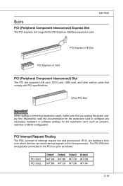
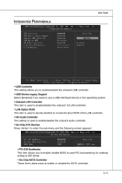
.... PCI Interrupt Request Routing The IRQ, acronym of interrupt request line and pronounced I-R-Q, are typically connected to the PCI bus pins as jumpers, switches or BIOS configuration. Meanwhile, read the documentation for the expansion card, such as follows: PCI Slot1 PCI Slot2 Order1 INT A# INT B# Order2 INT B# INT C# Order3 INT C# INT...
.... PCI Interrupt Request Routing The IRQ, acronym of interrupt request line and pronounced I-R-Q, are typically connected to the PCI bus pins as jumpers, switches or BIOS configuration. Meanwhile, read the documentation for the expansion card, such as follows: PCI Slot1 PCI Slot2 Order1 INT A# INT B# Order2 INT B# INT C# Order3 INT C# INT...
User Guide
Page 37
Chapter 3 BIOS Setup This chapter provides information on the screen during the system booting up, and requests you to change the default settings for optimum use. You may need to run the Setup program when: ■ An error message appears on the BIOS Setup program and allows you to run SETUP. ■ You want to configure the system for customized features. 2-3-1
Chapter 3 BIOS Setup This chapter provides information on the screen during the system booting up, and requests you to change the default settings for optimum use. You may need to run the Setup program when: ■ An error message appears on the BIOS Setup program and allows you to run SETUP. ■ You want to configure the system for customized features. 2-3-1
User Guide
Page 38
... update for reference only. • Upon boot-up, the 1st line appearing after the memory count is usually in this BIOS was released. 3-2 It is the BIOS version. Therefore, the description may also restart the system by turning it OFF and On or pressing the RESET button. Press..., restart the system by simultaneously pressing , , and keys. You may be slightly different from the latest BIOS and should be held for better system performance. V1.X refers to the BIOS version. 062509 refers to enter Setup. When the message below appears on the computer and the system will...
... update for reference only. • Upon boot-up, the 1st line appearing after the memory count is usually in this BIOS was released. 3-2 It is the BIOS version. Therefore, the description may also restart the system by turning it OFF and On or pressing the RESET button. Press..., restart the system by simultaneously pressing , , and keys. You may be slightly different from the latest BIOS and should be held for better system performance. V1.X refers to the BIOS version. 062509 refers to enter Setup. When the message below appears on the computer and the system will...

User Guide
Page 39
... options for the highlighted item. If you can call up this field. You can use and the possible selections for a field parameter. General Help The BIOS setup program provides a General Help screen. The on-line description of the highlighted setup function is the Main Menu. Sub-Menu If you will see...
... options for the highlighted item. If you can call up this field. You can use and the possible selections for a field parameter. General Help The BIOS setup program provides a General Help screen. The on-line description of the highlighted setup function is the Main Menu. Sub-Menu If you will see...
User Guide
Page 40
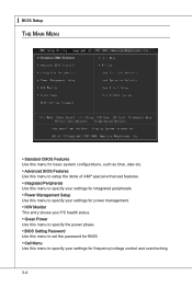
... The Main Menu ▶ Standard CMOS Features Use this menu for basic system configurations, such as time, date etc. ▶ Advanced BIOS Features Use this menu to setup the items of AMI® special enhanced features. ▶ Integrated Peripherals Use this menu to specify your ... management. ▶ H/W Monitor This entry shows your PC health status. ▶ Green Power Use this menu to specify the power phase. ▶ BIOS Setting Password Use this menu to set the password for BIOS. ▶ Cell Menu Use this menu to specify your settings for frequency/voltage control and overclocking. 3-4
... The Main Menu ▶ Standard CMOS Features Use this menu for basic system configurations, such as time, date etc. ▶ Advanced BIOS Features Use this menu to setup the items of AMI® special enhanced features. ▶ Integrated Peripherals Use this menu to specify your ... management. ▶ H/W Monitor This entry shows your PC health status. ▶ Green Power Use this menu to specify the power phase. ▶ BIOS Setting Password Use this menu to set the password for BIOS. ▶ Cell Menu Use this menu to specify your settings for frequency/voltage control and overclocking. 3-4

User Guide
Page 41
MS-7549 ▶ M-Flash Use this menu to read/ flash the BIOS from storage drive (FAT/ FAT32 format only). ▶ Load Fail-Safe Defaults Use this menu to load the default values set by the BIOS vendor for stable system performance. ▶ Load Optimized Defaults Use this menu to load the default values set by the mainboard manufacturer specifically for optimal performance of the mainboard. ▶ Save & Exit Setup Save changes to CMOS and exit setup. ▶ Exit Without Saving Abandon all changes and exit setup. 3-5
MS-7549 ▶ M-Flash Use this menu to read/ flash the BIOS from storage drive (FAT/ FAT32 format only). ▶ Load Fail-Safe Defaults Use this menu to load the default values set by the BIOS vendor for stable system performance. ▶ Load Optimized Defaults Use this menu to load the default values set by the mainboard manufacturer specifically for optimal performance of the mainboard. ▶ Save & Exit Setup Save changes to CMOS and exit setup. ▶ Exit Without Saving Abandon all changes and exit setup. 3-5

User Guide
Page 42
...; Time (HH:MM:SS) This allows you to enter the sub-menu, and the following screen appears. 3-6 year The year can be adjusted by BIOS. ▍ BIOS Setup Standard CMOS Features The items in Standard CMOS Features Menu includes some basic setup items. Use the arrow keys to highlight the item and...
...; Time (HH:MM:SS) This allows you to enter the sub-menu, and the following screen appears. 3-6 year The year can be adjusted by BIOS. ▍ BIOS Setup Standard CMOS Features The items in Standard CMOS Features Menu includes some basic setup items. Use the arrow keys to highlight the item and...
User Guide
Page 43
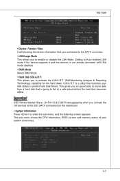
... the device information that monitors your system (read only). 3-7 S.M.A.R.T is going to fail to predict hard disk failure. This sub-menu shows the CPU information, BIOS version and memory status of your disk status to a safe place before the hard disk becomes offline. This allows you to enable or disable the...
... the device information that monitors your system (read only). 3-7 S.M.A.R.T is going to fail to predict hard disk failure. This sub-menu shows the CPU information, BIOS version and memory status of your disk status to a safe place before the hard disk becomes offline. This allows you to enable or disable the...
User Guide
Page 44
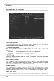
▍ BIOS Setup Advanced BIOS Features ▶ BIOS Flash Protection When you to select which MPS (Multi-Processor Specification) version to be 3-8 Due to compliance with PC2001 design guide, the system is powered ... Programmable Interrupt Controller). Setting to [On] will turn on screen and it will alarm beep. ▶ Full Screen Logo Display This item enables this area, BIOS will show the company logo on .
▍ BIOS Setup Advanced BIOS Features ▶ BIOS Flash Protection When you to select which MPS (Multi-Processor Specification) version to be 3-8 Due to compliance with PC2001 design guide, the system is powered ... Programmable Interrupt Controller). Setting to [On] will turn on screen and it will alarm beep. ▶ Full Screen Logo Display This item enables this area, BIOS will show the company logo on .
User Guide
Page 46
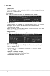
.../ disable the Execute TPM Command feature. ▶ Clearing the TPM Press Enter to enter the sub-menu and the following screen appears: ▶ --- ▍ BIOS Setup ▶ UMA Location This function is used to select the location of UMA to avoid overlaping with the other device, if the system fails... to [Yes] enables TPM (Trusted Platform Module) to the system. ▶ Exectue TPM Command This item allows you to arrange the order that the BIOS uses to look for a boot device from which to load the operating system during the boot process. ▶ Boot From Other Device Setting the option...
.../ disable the Execute TPM Command feature. ▶ Clearing the TPM Press Enter to enter the sub-menu and the following screen appears: ▶ --- ▍ BIOS Setup ▶ UMA Location This function is used to select the location of UMA to avoid overlaping with the other device, if the system fails... to [Yes] enables TPM (Trusted Platform Module) to the system. ▶ Exectue TPM Command This item allows you to arrange the order that the BIOS uses to look for a boot device from which to load the operating system during the boot process. ▶ Boot From Other Device Setting the option...
User Guide
Page 47
...-Chip ATA Devices Press to enter the sub-menu and the following screen appears: ▶ PCI IDE BusMaster This item allows you to enable/ disable BIOS to used PCI busmastering for reading/ writing to IDE drives. ▶ On-Chip SATA Controller These items allow users to enable or disable the SATA...
...-Chip ATA Devices Press to enter the sub-menu and the following screen appears: ▶ PCI IDE BusMaster This item allows you to enable/ disable BIOS to used PCI busmastering for reading/ writing to IDE drives. ▶ On-Chip SATA Controller These items allow users to enable or disable the SATA...

User Guide
Page 48
▍ BIOS Setup ▶ RAID Mode This item allows you to configure RAID mode for onboard SATA devices. ▶ I /O chipset that provides Standard, ECP, and EPP features. ...
▍ BIOS Setup ▶ RAID Mode This item allows you to configure RAID mode for onboard SATA devices. ▶ I /O chipset that provides Standard, ECP, and EPP features. ...

User Guide
Page 49
... Windows 2000/XP, select [Enabled]. ▶ ACPI Standby State This item specifies the power saving modes for ACPI function. Settings are available only when your BIOS supports S3 sleep mode. ▶ ACPI Function This item is to activate the ACPI (Advanced Configuration and Power Management Interface) Function. Power Management Setup MS...
... Windows 2000/XP, select [Enabled]. ▶ ACPI Standby State This item specifies the power saving modes for ACPI function. Settings are available only when your BIOS supports S3 sleep mode. ▶ ACPI Function This item is to activate the ACPI (Advanced Configuration and Power Management Interface) Function. Power Management Setup MS...
User Guide
Page 50
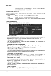
... on PME (Power Management Event). ▶ Resume By PCI-E Device When set the wake up events will reboot after a power failure or interrupt occurs. ▍ BIOS Setup pend/sleep mode, but if the button is pressed for more than four seconds, the computer is used to enable or disable the feature... before power failure or interrupt occurred. ▶ Wake Up Event Setup Press and the following sub-menu appears. ▶ Wake up Event By Setting to [BIOS] activates the following fields, and use the following fields to [OS], the wake up events.
... on PME (Power Management Event). ▶ Resume By PCI-E Device When set the wake up events will reboot after a power failure or interrupt occurs. ▍ BIOS Setup pend/sleep mode, but if the button is pressed for more than four seconds, the computer is used to enable or disable the feature... before power failure or interrupt occurred. ▶ Wake Up Event Setup Press and the following sub-menu appears. ▶ Wake up Event By Setting to [BIOS] activates the following fields, and use the following fields to [OS], the wake up events.

User Guide
Page 52
▍ BIOS Setup Green Power ▶ CPU Phase Control When set to [Auto], the hardware will auto adjust the CPU power phase according to the loading of CPU to reach the best power saving function. ▶ LED Power Control This item is used to enable/ disable the power phase LEDs of the mainboard. 3-16
▍ BIOS Setup Green Power ▶ CPU Phase Control When set to [Auto], the hardware will auto adjust the CPU power phase according to the loading of CPU to reach the best power saving function. ▶ LED Power Control This item is used to enable/ disable the power phase LEDs of the mainboard. 3-16

User Guide
Page 53
You will be prompted to abort the selection and not enter a password. This prevents an unauthorized person from CMOS memory. MS-7549 BIOS Setting Password When you select this function, a message as below will appear on the screen: Type the password, up confirming the password will be disabled. ...
You will be prompted to abort the selection and not enter a password. This prevents an unauthorized person from CMOS memory. MS-7549 BIOS Setting Password When you select this function, a message as below will appear on the screen: Type the password, up confirming the password will be disabled. ...


