
User Guide
Page 2
...® is registered trademark of JMicron Technology Corporation. ■ Netware® is a registered trademark of purchase or local distributor. Alternatively, please try the following help resources for further guidance. ◙ Visit the MSI website for FAQ, technical guide, BIOS updates, driver updates, and other information: http://www.msi.com/index.php?func=service ◙ Contact our technical staff at...
...® is registered trademark of JMicron Technology Corporation. ■ Netware® is a registered trademark of purchase or local distributor. Alternatively, please try the following help resources for further guidance. ◙ Visit the MSI website for FAQ, technical guide, BIOS updates, driver updates, and other information: http://www.msi.com/index.php?func=service ◙ Contact our technical staff at...

User Guide
Page 8
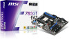
...Technical Support ii Safety Instructions iii FCC-B Radio Frequency Interference Statement iv WEEE (Waste Electrical and Electronic Equipment) Statement v Chapter 1 Getting Started 1-1 Mainboard Specifications 1-2 Mainboard Layout 1-4 Packing Checklist 1-5 Chapter 2 Hardware Setup 2-1 Quick Components Guide 2-2 CPU (Central Processing Unit 2-3 Memory 2-6 Power Supply 2-8 Back Panel 2-9 Connectors 2-11 Switch 2-17 Button 2-18 Slots 2-19 LED Status Indicators 2-20 Chapter 3 BIOS Setup 3-1 Entering Setup 3-2 The Main Menu 3-4 Standard CMOS Features 3-6 Advanced BIOS Features...
...Technical Support ii Safety Instructions iii FCC-B Radio Frequency Interference Statement iv WEEE (Waste Electrical and Electronic Equipment) Statement v Chapter 1 Getting Started 1-1 Mainboard Specifications 1-2 Mainboard Layout 1-4 Packing Checklist 1-5 Chapter 2 Hardware Setup 2-1 Quick Components Guide 2-2 CPU (Central Processing Unit 2-3 Memory 2-6 Power Supply 2-8 Back Panel 2-9 Connectors 2-11 Switch 2-17 Button 2-18 Slots 2-19 LED Status Indicators 2-20 Chapter 3 BIOS Setup 3-1 Entering Setup 3-2 The Main Menu 3-4 Standard CMOS Features 3-6 Advanced BIOS Features...
User Guide
Page 12
....msi.com/index.php?func=testreport) LAN ■ Supports LAN 10/100/1000 Fast Ethernet by Realtek® RTL 8111DL Audio ■ Chip integrated by Realtek® ALC889/ ALC888S V2 ■ Flexible 8-channel audio with jack sensing ■ Compliant with Azalia 1.0 Spec IDE ■ 1 IDE port by AMD® SB750/ SB710 ■ Supports Ultra DMA 66/100/133, PIO & Bus Master operation mode SATA ■ 5 SATAII ports by AMD...
....msi.com/index.php?func=testreport) LAN ■ Supports LAN 10/100/1000 Fast Ethernet by Realtek® RTL 8111DL Audio ■ Chip integrated by Realtek® ALC889/ ALC888S V2 ■ Flexible 8-channel audio with jack sensing ■ Compliant with Azalia 1.0 Spec IDE ■ 1 IDE port by AMD® SB750/ SB710 ■ Supports Ultra DMA 66/100/133, PIO & Bus Master operation mode SATA ■ 5 SATAII ports by AMD...
User Guide
Page 22
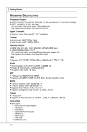
...; DDR2 memory modules are used for Dual-Channel mode. ▍ Hardware Setup Memory These DIMM slots are not interchangeable with two data bus lines simultaneously. Enabling Dual-Channel mode can transmit and receive data with DDR and the DDR2 standard is not backwards compatible. You should always install DDR2 memory modules in the DDR2 DIMM slots. • In Dual-Channel mode, make sure that you install memory modules of the same type and...
...; DDR2 memory modules are used for Dual-Channel mode. ▍ Hardware Setup Memory These DIMM slots are not interchangeable with two data bus lines simultaneously. Enabling Dual-Channel mode can transmit and receive data with DDR and the DDR2 standard is not backwards compatible. You should always install DDR2 memory modules in the DDR2 DIMM slots. • In Dual-Channel mode, make sure that you install memory modules of the same type and...
User Guide
Page 25
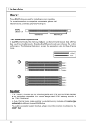
... Area Network (LAN). The computer is communicating with another computer on a single cable. ▶ eSATA Port The eSATA port is for attaching the eSATA external hard drive. ▶ LAN The standard RJ-45 LAN jack is for monitor. ▶ DVI-D Port The DVI-D (Digital Visual Interface-Digital) connector allows you to connect a LCD monitor. It provides a high-speed digital interconnection between the computer and its display device. To connect...
... Area Network (LAN). The computer is communicating with another computer on a single cable. ▶ eSATA Port The eSATA port is for attaching the eSATA external hard drive. ▶ LAN The standard RJ-45 LAN jack is for monitor. ▶ DVI-D Port The DVI-D (Digital Visual Interface-Digital) connector allows you to connect a LCD monitor. It provides a high-speed digital interconnection between the computer and its display device. To connect...
User Guide
Page 27
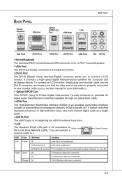
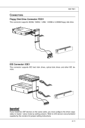
... / slave mode by the vendors for jumper setting instructions. 2-11 MS-7551 Connectors Floppy Disk Drive Connector: FDD1 This connector supports 360KB, 720KB, 1.2MB, 1.44MB or 2.88MB floppy disk drive. Fl opMpySDI Kdkldkddfkkakfskkdskkdakaddfdddffdfkad-dkdffdldkddjadfdsdddjfdddffkadasdfdddffdfadasfsadfddsddadasdsaddsdafsddadsdddfdsadddfffaffsfsdasfdfffdf 5 D 1i s/k4"DFr il voeppCyonnect or 3 1/2" F l oppy D i sk D r i ve Connector 3 1/2" F l oppy D i sk D ri ve Connector IDE Connector: IDE1 This connector supports IDE hard disk drives, optical disk drives and other IDE devices. Fl...
... / slave mode by the vendors for jumper setting instructions. 2-11 MS-7551 Connectors Floppy Disk Drive Connector: FDD1 This connector supports 360KB, 720KB, 1.2MB, 1.44MB or 2.88MB floppy disk drive. Fl opMpySDI Kdkldkddfkkakfskkdskkdakaddfdddffdfkad-dkdffdldkddjadfdsdddjfdddffkadasdfdddffdfadasfsadfddsddadasdsaddsdafsddadsdddfdsadddfffaffsfsdasfdfffdf 5 D 1i s/k4"DFr il voeppCyonnect or 3 1/2" F l oppy D i sk D r i ve Connector 3 1/2" F l oppy D i sk D ri ve Connector IDE Connector: IDE1 This connector supports IDE hard disk drives, optical disk drives and other IDE devices. Fl...
User Guide
Page 29
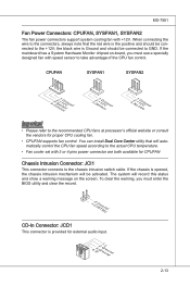
... for proper CPU cooling fan. • CPUFAN supports fan control. To clear the warning, you must enter the BIOS utility and clear the record. 1.C2.IGNTroRuUnd CD-In Connector: JCD1 This connector is Ground and should be connected to the +12V; If the mainboard has a System Hardware Monitor chipset on the screen. If the chassis is the positive and should be activated. When connecting the wire to the connectors, always note...
... for proper CPU cooling fan. • CPUFAN supports fan control. To clear the warning, you must enter the BIOS utility and clear the record. 1.C2.IGNTroRuUnd CD-In Connector: JCD1 This connector is Ground and should be connected to the +12V; If the mainboard has a System Hardware Monitor chipset on the screen. If the chassis is the positive and should be activated. When connecting the wire to the connectors, always note...
User Guide
Page 34
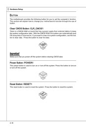
... explain how to keep the system configuration data. Clear CMOS Button: CLR_CMOS1 There is used to turn -off the system before clearing CMOS data. ▍ Hardware Setup Button The motherboard provides the following button for you want to clear the system configuration, use of button. Reset Button: RESET1 This reset button is a CMOS RAM on or turn -on . Important Make sure that has a power supply from external battery to change your motherboard's function through the use the button to clear data.
... explain how to keep the system configuration data. Clear CMOS Button: CLR_CMOS1 There is used to turn -off the system before clearing CMOS data. ▍ Hardware Setup Button The motherboard provides the following button for you want to clear the system configuration, use of button. Reset Button: RESET1 This reset button is a CMOS RAM on or turn -on . Important Make sure that has a power supply from external battery to change your motherboard's function through the use the button to clear data.
User Guide
Page 35
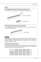
... Slot PCI Express x1 Slot PCI (Peripheral Component Interconnect) Slot The PCI slot supports LAN card, SCSI card, USB card, and other add-on cards that comply with PCI specifications. 32-bit PCI Slot Important When adding or removing expansion cards, make sure that you unplug the power supply first. PCI Interrupt Request Routing The IRQ, acronym of interrupt request line and pronounced I-R-Q, are typically connected to the PCI bus pins as jumpers, switches or BIOS configuration. MS-7551 Slots PCI (Peripheral Component Interconnect) Express Slot The PCI Express slot supports...
... Slot PCI Express x1 Slot PCI (Peripheral Component Interconnect) Slot The PCI slot supports LAN card, SCSI card, USB card, and other add-on cards that comply with PCI specifications. 32-bit PCI Slot Important When adding or removing expansion cards, make sure that you unplug the power supply first. PCI Interrupt Request Routing The IRQ, acronym of interrupt request line and pronounced I-R-Q, are typically connected to the PCI bus pins as jumpers, switches or BIOS configuration. MS-7551 Slots PCI (Peripheral Component Interconnect) Express Slot The PCI Express slot supports...
User Guide
Page 43
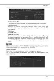
... allows you connect the HD devices to the IDE/ SATA connectors on the mainboard. ▶ System Information Press to enter the sub-menu, and the following screen appears. Important IDE Primary Master/ Slave , SATA1~5 & E-SATA are appearing when you to activate the S.M.A.R.T. (Self-Monitoring Analysis & Reporting Technology) capability for the hard disks. This sub-menu shows the CPU information, BIOS version and memory status of your disk status to predict hard disk failure. S.M.A.R.T is...
... allows you connect the HD devices to the IDE/ SATA connectors on the mainboard. ▶ System Information Press to enter the sub-menu, and the following screen appears. Important IDE Primary Master/ Slave , SATA1~5 & E-SATA are appearing when you to activate the S.M.A.R.T. (Self-Monitoring Analysis & Reporting Technology) capability for the hard disks. This sub-menu shows the CPU information, BIOS version and memory status of your disk status to predict hard disk failure. S.M.A.R.T is...
User Guide
Page 44
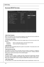
... skip some check items. ▶ Boot Up Num Lock LED This setting is to set the Num Lock status when the system is powered on . ▍ BIOS Setup Advanced BIOS Features ▶ BIOS Flash Protection When you to select which MPS (Multi-Processor Specification) version to be 3-8 Setting to [Off] will alarm beep. ▶ Full Screen Logo Display This item enables this area, BIOS will show the company logo...
... skip some check items. ▶ Boot Up Num Lock LED This setting is to set the Num Lock status when the system is powered on . ▍ BIOS Setup Advanced BIOS Features ▶ BIOS Flash Protection When you to select which MPS (Multi-Processor Specification) version to be 3-8 Setting to [Off] will alarm beep. ▶ Full Screen Logo Display This item enables this area, BIOS will show the company logo...
User Guide
Page 45
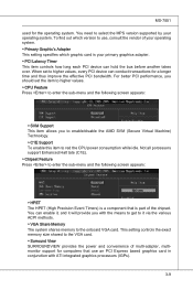
...; CPU Feature Press to enter the sub-menu and the following screen appears: ▶ HPET The HPET (High Precision Event Timers) is a component that use an PCI Express based graphics card in conjunction with the means to get to it will provide you to enable/disable the AMD SVM (Secure Virtual Machine) Technology. ▶ C1E Support To enable this item to select the MPS version supported by your primary graphics...
...; CPU Feature Press to enter the sub-menu and the following screen appears: ▶ HPET The HPET (High Precision Event Timers) is a component that use an PCI Express based graphics card in conjunction with the means to get to it will provide you to enable/disable the AMD SVM (Secure Virtual Machine) Technology. ▶ C1E Support To enable this item to select the MPS version supported by your primary graphics...
User Guide
Page 47
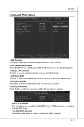
... to enable/disable the onboard USB controller. ▶ USB Device Legacy Support Select [Enabled] if you need to use a USB-interfaced device in the operating system. ▶ Onboard LAN Controller This item is used to enable/disable the onboard 1st LAN controller. ▶ LAN Option ROM This item is used to decide whether to invoke the Boot ROM of the LAN controller. ▶ HD Audio Controller This setting is used to enable/disable the onboard audio controller. ▶ On-Chip ATA Devices Press to enter the sub-menu and the following screen appears: ▶ PCI IDE...
... to enable/disable the onboard USB controller. ▶ USB Device Legacy Support Select [Enabled] if you need to use a USB-interfaced device in the operating system. ▶ Onboard LAN Controller This item is used to enable/disable the onboard 1st LAN controller. ▶ LAN Option ROM This item is used to decide whether to invoke the Boot ROM of the LAN controller. ▶ HD Audio Controller This setting is used to enable/disable the onboard audio controller. ▶ On-Chip ATA Devices Press to enter the sub-menu and the following screen appears: ▶ PCI IDE...
User Guide
Page 49
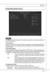
... sleep mode is to save energy. Settings are: [Power Off] The power button functions as Windows 2000/XP, select [Enabled]. ▶ ACPI Standby State This item specifies the power saving modes for ACPI function. The information stored in memory will be used to restore the system when a "wake up" event occurs. ▶ Power Button Function This feature sets the function of system configuration and open applications/files is saved to main memory...
... sleep mode is to save energy. Settings are: [Power Off] The power button functions as Windows 2000/XP, select [Enabled]. ▶ ACPI Standby State This item specifies the power saving modes for ACPI function. The information stored in memory will be used to restore the system when a "wake up" event occurs. ▶ Power Button Function This feature sets the function of system configuration and open applications/files is saved to main memory...
User Guide
Page 50
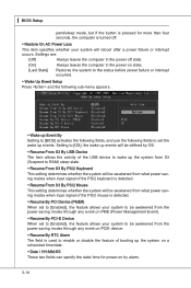
▍ BIOS Setup pend/sleep mode, but if the button is pressed for power-on by OS. ▶ Resume From S3 By USB Device The item allows the activity of the USB device to wake up the system from S3 (Suspend to RAM) sleep state. ▶ Resume From S3 By PS/2 Keyboard This setting determines whether the system will be awakened from what power saving modes when input...
▍ BIOS Setup pend/sleep mode, but if the button is pressed for power-on by OS. ▶ Resume From S3 By USB Device The item allows the activity of the USB device to wake up the system from S3 (Suspend to RAM) sleep state. ▶ Resume From S3 By PS/2 Keyboard This setting determines whether the system will be awakened from what power saving modes when input...
User Guide
Page 51
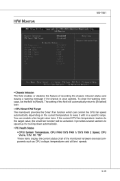
... display the current status of all of recording the chassis intrusion status and issuing a warning message if the chassis is once opened. You can control the CPU fan speed automatically depending on the current temperature to [Reset]. The setting of the field will be activated. H/W Monitor MS-7551 ▶ Chassis Intrusion The field enables or disables the feature of the monitored hardware devices/components such as CPU voltage, temperatures...
... display the current status of all of recording the chassis intrusion status and issuing a warning message if the chassis is once opened. You can control the CPU fan speed automatically depending on the current temperature to [Reset]. The setting of the field will be activated. H/W Monitor MS-7551 ▶ Chassis Intrusion The field enables or disables the feature of the monitored hardware devices/components such as CPU voltage, temperatures...
User Guide
Page 60
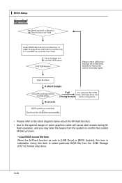
Using this item is selectable. ▍ BIOS Setup Important • Please refer to the block diagram below about the M-Flash function. • Due to select particular BIOS file from When the M-Flash function as sets to [USB Drive] or [BIOS Update], this item to the special design of some graphics cards will cause dark screen during M- flash operation, and you may refer the beeps from the system to confirm the current M-flash process. ▶ Load BIOS source file from the USB/ Storage (FAT/32 format only) drive. 3-24
Using this item is selectable. ▍ BIOS Setup Important • Please refer to the block diagram below about the M-Flash function. • Due to select particular BIOS file from When the M-Flash function as sets to [USB Drive] or [BIOS Update], this item to the special design of some graphics cards will cause dark screen during M- flash operation, and you may refer the beeps from the system to confirm the current M-flash process. ▶ Load BIOS source file from the USB/ Storage (FAT/32 format only) drive. 3-24
User Guide
Page 92
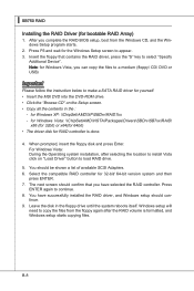
... the instruction below to appear. 3. Note: for yourself. • Insert the MSI DVD into the DVD-ROM drive. • Click the "Browse CD" on "Load Driver" button to select "Specify Additional Device". Press ENTER again to copy the files from the Windows CD, and the Windows Setup program starts. 2. When prompted, insert the floppy disk and press Enter. The next screen should confirm that contains the RAID driver, press the "S" key to load RAID drive. 5. You...
... the instruction below to appear. 3. Note: for yourself. • Insert the MSI DVD into the DVD-ROM drive. • Click the "Browse CD" on "Load Driver" button to select "Specify Additional Device". Press ENTER again to copy the files from the Windows CD, and the Windows Setup program starts. 2. When prompted, insert the floppy disk and press Enter. The next screen should confirm that contains the RAID driver, press the "S" key to load RAID drive. 5. You...

User Guide
Page 93
The DVD will auto-run and the setup screen will be automatically installed. The driver will appear. 3. Insert the MSI DVD into the DVD-ROM drive. 2. The AMD chipset drivers includes RAID Driver. 4. Under the Driver tab, click on AMD chipset drivers by your need. MS-7551 Installing the RAID Driver Under Windows (for Non-bootable RAID Array) 1. B-9
The DVD will auto-run and the setup screen will be automatically installed. The driver will appear. 3. Insert the MSI DVD into the DVD-ROM drive. 2. The AMD chipset drivers includes RAID Driver. 4. Under the Driver tab, click on AMD chipset drivers by your need. MS-7551 Installing the RAID Driver Under Windows (for Non-bootable RAID Array) 1. B-9
User Guide
Page 97
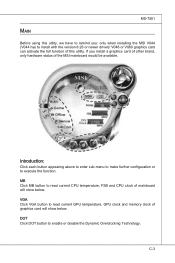
... utility, we have to remind you install a graphics card of other brand, only hardware status of the MSI mainboard would be available. Introduction: Click each button appearing above to enter sub-menu to make further configuration or to enable or disable the Dynamic Overclocking Technology. C-3 MS-7551 Main Before using this utility. If you : only when installing the MSI V044 (V044 has to read current GPU temperature, GPU clock and memory clock of graphics card...
... utility, we have to remind you install a graphics card of other brand, only hardware status of the MSI mainboard would be available. Introduction: Click each button appearing above to enter sub-menu to make further configuration or to enable or disable the Dynamic Overclocking Technology. C-3 MS-7551 Main Before using this utility. If you : only when installing the MSI V044 (V044 has to read current GPU temperature, GPU clock and memory clock of graphics card...


