User Guide
Page 2
...785GM-E51 & 760GM-E51 Date August 2009 Technical Support If a problem arises with your system and no guarantee is given as to make changes without notice. Revision History Revision V1.4 Revision History Release for FAQ, technical guide, BIOS updates, driver updates, and other information: http://www.msi...; is registered trademark of Micro-Star Int'l Co.,Ltd. ■ NVIDIA® is registered trademark of NVIDIA Corporation. ■ ATI® is registered trademark of ATI Technologies, Inc. ■ AMD® is registered trademarks of AMD Corporation. ■ Intel® is ...
...785GM-E51 & 760GM-E51 Date August 2009 Technical Support If a problem arises with your system and no guarantee is given as to make changes without notice. Revision History Revision V1.4 Revision History Release for FAQ, technical guide, BIOS updates, driver updates, and other information: http://www.msi...; is registered trademark of Micro-Star Int'l Co.,Ltd. ■ NVIDIA® is registered trademark of NVIDIA Corporation. ■ ATI® is registered trademark of ATI Technologies, Inc. ■ AMD® is registered trademarks of AMD Corporation. ■ Intel® is ...
User Guide
Page 8
... 2-1 Quick Components Guide 2-2 CPU (Central Processing Unit 2-3 Memory 2-6 Power Supply 2-8 Back Panel 2-9 Connectors 2-11 Jumpers 2-18 Switch 2-19 Slots 2-20 LED Status Indicators 2-23 Chapter 3 BIOS Setup 3-1 Entering Setup 3-2 The Main Menu 3-4 Standard CMOS Features 3-6 Advanced BIOS Features 3-9 Integrated Peripherals 3-12 Power Management Setup 3-14 H/W Monitor 3-16 Green Power 3-17...
... 2-1 Quick Components Guide 2-2 CPU (Central Processing Unit 2-3 Memory 2-6 Power Supply 2-8 Back Panel 2-9 Connectors 2-11 Jumpers 2-18 Switch 2-19 Slots 2-20 LED Status Indicators 2-23 Chapter 3 BIOS Setup 3-1 Entering Setup 3-2 The Main Menu 3-4 Standard CMOS Features 3-6 Advanced BIOS Features 3-9 Integrated Peripherals 3-12 Power Management Setup 3-14 H/W Monitor 3-16 Green Power 3-17...

User Guide
Page 27
Otherwise, data loss may occur during transmission. To clear the warning, you must enter the BIOS utility and clear the record. 1.C2.IGNTroRuUnd 2-12 The system will be activated. Chassis Intrusion Connector: JCI1 This connector connects to one Serial ATA device. &#...
Otherwise, data loss may occur during transmission. To clear the warning, you must enter the BIOS utility and clear the record. 1.C2.IGNTroRuUnd 2-12 The system will be activated. Chassis Intrusion Connector: JCI1 This connector connects to one Serial ATA device. &#...

User Guide
Page 36
...Click Apply. Select "Enable CrossFire™". 5. To avoid the issue, please follow the steps below to http://game.amd.com/us-en/crossfirex_hybrid.aspx Important Changing integrated graphic memory operating mode may cause Hybrid CrossFireX™ fail. More details ...VGA. • Save BIOS settings and reboot. • Enable the Hybrid CrossFireX™ in the Catalyst Control Center, click CrossFire™. 3. From the "Graphics Adapter" list, select the graphics card that acts as are all cards in the configuration as the Display GPU. 4. MS-7596 2. When Hybrid CrossFireX&#...
...Click Apply. Select "Enable CrossFire™". 5. To avoid the issue, please follow the steps below to http://game.amd.com/us-en/crossfirex_hybrid.aspx Important Changing integrated graphic memory operating mode may cause Hybrid CrossFireX™ fail. More details ...VGA. • Save BIOS settings and reboot. • Enable the Hybrid CrossFireX™ in the Catalyst Control Center, click CrossFire™. 3. From the "Graphics Adapter" list, select the graphics card that acts as are all cards in the configuration as the Display GPU. 4. MS-7596 2. When Hybrid CrossFireX&#...
User Guide
Page 37
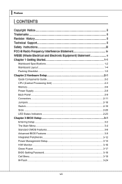
The PCI IRQ pins are hardware lines over which devices can send interrupt signals to the PCI bus pins as jumpers, switches or BIOS configuration. PCI Interrupt Request Routing The IRQ, acronym of interrupt request line and pronounced I-R-Q, are typically connected to the microprocessor. Meanwhile, read the documentation for ...
The PCI IRQ pins are hardware lines over which devices can send interrupt signals to the PCI bus pins as jumpers, switches or BIOS configuration. PCI Interrupt Request Routing The IRQ, acronym of interrupt request line and pronounced I-R-Q, are typically connected to the microprocessor. Meanwhile, read the documentation for ...

User Guide
Page 40
Chapter 3 BIOS Setup This chapter provides information on the screen during the system booting up, and requests you to change the default settings for optimum use. You may need to run the Setup program when: ■ An error message appears on the BIOS Setup program and allows you to run SETUP. ■ You want to configure the system for customized features. 2-3-1
Chapter 3 BIOS Setup This chapter provides information on the screen during the system booting up, and requests you to change the default settings for optimum use. You may need to run the Setup program when: ■ An error message appears on the BIOS Setup program and allows you to run SETUP. ■ You want to configure the system for customized features. 2-3-1

User Guide
Page 41
...and On or pressing the RESET button. V2.1 refers to the BIOS version. 070509 refers to the customer as I = Intel, N = NVIDIA, A = AMD and V = VIA. 7th - 8th digit refers to the date this chapter are under each BIOS category described in the format: A7596AMS V2.1 070509 where: 1st digit... refers to BIOS maker as A = AMI, W = AWARD, and P = PHOENIX. 2nd - 5th digit refers...
...and On or pressing the RESET button. V2.1 refers to the BIOS version. 070509 refers to the customer as I = Intel, N = NVIDIA, A = AMD and V = VIA. 7th - 8th digit refers to the date this chapter are under each BIOS category described in the format: A7596AMS V2.1 070509 where: 1st digit... refers to BIOS maker as A = AMI, W = AWARD, and P = PHOENIX. 2nd - 5th digit refers...
User Guide
Page 42
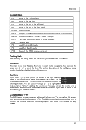
... the Setup menu, the first menu you want to return to field within a sub-menu. General Help The BIOS setup program provides a General Help screen. Press to call up the sub-menu. MS-7596 Control Keys Move to the previous item Move to the next item Move to the item in the...
... the Setup menu, the first menu you want to return to field within a sub-menu. General Help The BIOS setup program provides a General Help screen. Press to call up the sub-menu. MS-7596 Control Keys Move to the previous item Move to the next item Move to the item in the...

User Guide
Page 43
...; Standard CMOS Features Use this menu for basic system configurations, such as time, date etc. ▶ Advanced BIOS Features Use this menu to setup the items of the BIOS special enhanced features. ▶ Integrated Peripherals Use this menu to specify your settings for integrated peripherals. ▶ ... Monitor This entry shows your PC health status. ▶ Green Power Use this menu to specify the power phase. ▶ BIOS Setting Password Use this menu to set the password for BIOS. ▶ Cell Menu Use this menu to specify your settings for frequency/voltage control and overclocking. 3-4
...; Standard CMOS Features Use this menu for basic system configurations, such as time, date etc. ▶ Advanced BIOS Features Use this menu to setup the items of the BIOS special enhanced features. ▶ Integrated Peripherals Use this menu to specify your settings for integrated peripherals. ▶ ... Monitor This entry shows your PC health status. ▶ Green Power Use this menu to specify the power phase. ▶ BIOS Setting Password Use this menu to set the password for BIOS. ▶ Cell Menu Use this menu to specify your settings for frequency/voltage control and overclocking. 3-4

User Guide
Page 44
MS-7596 ▶ M-Flash Use this menu to read/ flash the BIOS from storage drive (FAT/ FAT32 format only). ▶ User Settings Use this menu to save/ load your settings to/ from CMOS for BIOS. ▶ Load Fail-Safe Defaults Use this menu to load the default values set by the BIOS vendor for stable...
MS-7596 ▶ M-Flash Use this menu to read/ flash the BIOS from storage drive (FAT/ FAT32 format only). ▶ User Settings Use this menu to save/ load your settings to/ from CMOS for BIOS. ▶ Load Fail-Safe Defaults Use this menu to load the default values set by the BIOS vendor for stable...

User Guide
Page 45
... time format is . [day] Day of the week, from 1 to 31 can be keyed by numeric function keys. [year] The year can be adjusted by BIOS. The format is . 3-6 through Dec. [date] The date from Sun to Sat, determined by users. ▶ Time (HH:MM:SS) This allows you to set... the system to the date that you want (usually the current time). only. [month] The month from Jan. ▍ BIOS Setup Standard CMOS Features The items in Standard CMOS Features Menu include some basic setup items. Use the arrow keys to highlight the item and...
... time format is . [day] Day of the week, from 1 to 31 can be keyed by numeric function keys. [year] The year can be adjusted by BIOS. The format is . 3-6 through Dec. [date] The date from Sun to Sat, determined by users. ▶ Time (HH:MM:SS) This allows you to set... the system to the date that you want (usually the current time). only. [month] The month from Jan. ▍ BIOS Setup Standard CMOS Features The items in Standard CMOS Features Menu include some basic setup items. Use the arrow keys to highlight the item and...
User Guide
Page 47
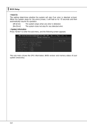
▍ BIOS Setup ▶ Hold On The setting determines whether the system will halt on for any error is detected. [No Error] The system does not stop if an error is detected at boot. This sub-menu shows the CPU information, BIOS version and memory status of your system (read only). 3-8 When the system stops for the errors preset, it will stop for 15 seconds and then automatically resume its operation. [All Error] The system stops when any detected error. ▶ System Information Press to enter the sub-menu, and the following screen appears.
▍ BIOS Setup ▶ Hold On The setting determines whether the system will halt on for any error is detected. [No Error] The system does not stop if an error is detected at boot. This sub-menu shows the CPU information, BIOS version and memory status of your system (read only). 3-8 When the system stops for the errors preset, it will stop for 15 seconds and then automatically resume its operation. [All Error] The system stops when any detected error. ▶ System Information Press to enter the sub-menu, and the following screen appears.

User Guide
Page 48
... to protect it against viruses. ▶ Full Screen Logo Display This item enables this Flash BIOS Protection function. Settings are: [Enabled] Shows a still image (logo) on . Advanced BIOS Features MS-7596 ▶ BIOS Flash Protection This function protects the BIOS from accidental corruption by unauthorized users or computer viruses. Setting to [Off] will allow users...
... to protect it against viruses. ▶ Full Screen Logo Display This item enables this Flash BIOS Protection function. Settings are: [Enabled] Shows a still image (logo) on . Advanced BIOS Features MS-7596 ▶ BIOS Flash Protection This function protects the BIOS from accidental corruption by unauthorized users or computer viruses. Setting to [Off] will allow users...
User Guide
Page 49
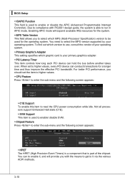
... via the various ACPI methods. 3-10 Enabling APIC mode will provide you to select which graphic card is able to run in APIC mode. ▍ BIOS Setup ▶ IOAPIC Function This field is used to enable/ disable SVM. ▶ Chipset Feature Press to enter the sub-menu and the following screen...
... via the various ACPI methods. 3-10 Enabling APIC mode will provide you to select which graphic card is able to run in APIC mode. ▍ BIOS Setup ▶ IOAPIC Function This field is used to enable/ disable SVM. ▶ Chipset Feature Press to enter the sub-menu and the following screen...

User Guide
Page 50
... to enter the sub-menu and the following screen appears: ▶ 1st Boot Device This item allows you to set the first boot device where BIOS attempts to load the disk operating system. ▶ Boot From Other Device Setting the option to [Yes] allows the system to try to boot from... the TPM Press Enter to allocate the memory for onboard VGA. ▶ VGA Share Memory The system shares memory to the onboard VGA card. MS-7596 ▶ On-chip VGA This item specifies whether to clear the TPM status. 3-11 Setting to [UMA], allocates the system share memory for onboard VGA...
... to enter the sub-menu and the following screen appears: ▶ 1st Boot Device This item allows you to set the first boot device where BIOS attempts to load the disk operating system. ▶ Boot From Other Device Setting the option to [Yes] allows the system to try to boot from... the TPM Press Enter to allocate the memory for onboard VGA. ▶ VGA Share Memory The system shares memory to the onboard VGA card. MS-7596 ▶ On-chip VGA This item specifies whether to clear the TPM status. 3-11 Setting to [UMA], allocates the system share memory for onboard VGA...
User Guide
Page 51
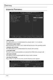
▍ BIOS Setup Integrated Peripherals ▶ USB Controller This setting allows you to enable/disable the onboard USB 1.1/ 2.0 controller. ▶ USB Device Legacy Support Select [Enabled] if ...
▍ BIOS Setup Integrated Peripherals ▶ USB Controller This setting allows you to enable/disable the onboard USB 1.1/ 2.0 controller. ▶ USB Device Legacy Support Select [Enabled] if ...

User Guide
Page 52
... Parallel Port only, choose [SPP]. To operate the onboard parallel port in the EPP mode simultaneously, choose [EPP]. MS-7596 ▶ PCI IDE BusMaster This item allows you to enable/ disable BIOS to used PCI busmastering for reading/ writing to IDE drives. ▶ OnChip SATA Controller This item allows users to enable...
... Parallel Port only, choose [SPP]. To operate the onboard parallel port in the EPP mode simultaneously, choose [EPP]. MS-7596 ▶ PCI IDE BusMaster This item allows you to enable/ disable BIOS to used PCI busmastering for reading/ writing to IDE drives. ▶ OnChip SATA Controller This item allows users to enable...
User Guide
Page 53
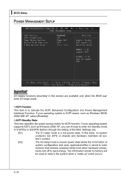
▍ BIOS Setup Power Management Setup Important S3-related functions described in this section are : [S1] The S1 sleep mode is a low power state. In this field. .../ 2000/ ME/ XP, select [Enabled]. ▶ ACPI Standby State This item specifies the power saving modes for ACPI function. Settings are available only when the BIOS supports S3 sleep mode. ▶ ACPI Function This item is ACPI-aware, such as Windows 2000/ XP, you can choose to restore the system when...
▍ BIOS Setup Power Management Setup Important S3-related functions described in this section are : [S1] The S1 sleep mode is a low power state. In this field. .../ 2000/ ME/ XP, select [Enabled]. ▶ ACPI Standby State This item specifies the power saving modes for ACPI function. Settings are available only when the BIOS supports S3 sleep mode. ▶ ACPI Function This item is ACPI-aware, such as Windows 2000/ XP, you can choose to restore the system when...

User Guide
Page 54
... your system will be awakened from what power saving modes when input signal of the PS/2 keyboard/ mouse is used to wake up events. MS-7596 ▶ Power Button Function This feature sets the function of booting up the system on a scheduled time/date. 3-15 Settings are : [Off] Always... failure or interrupt occurred. ▶ Wake Up Event Setup Press and the following sub-menu appears. ▶ Wake Up Event By Setting to [BIOS] activates the following fields, and use the following fields to set to [Enabled], the feature allows your system to be awakened from the power saving...
... your system will be awakened from what power saving modes when input signal of the PS/2 keyboard/ mouse is used to wake up events. MS-7596 ▶ Power Button Function This feature sets the function of booting up the system on a scheduled time/date. 3-15 Settings are : [Off] Always... failure or interrupt occurred. ▶ Wake Up Event Setup Press and the following sub-menu appears. ▶ Wake Up Event By Setting to [BIOS] activates the following fields, and use the following fields to set to [Enabled], the feature allows your system to be awakened from the power saving...

User Guide
Page 55
... automatically return to [Enabled] later. ▶ CPU Smart FAN Target The mainboard provides the Smart Fan function which can enable a fan target value here. ▍ BIOS Setup H/W Monitor ▶ Chassis Intrusion The field enables or disables the feature of the field will be activated. It provides several sections to speed up...
... automatically return to [Enabled] later. ▶ CPU Smart FAN Target The mainboard provides the Smart Fan function which can enable a fan target value here. ▍ BIOS Setup H/W Monitor ▶ Chassis Intrusion The field enables or disables the feature of the field will be activated. It provides several sections to speed up...


