
Operators Manual EN
Page 70
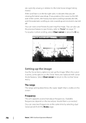
... key. You can view sonar history by selecting dual Sonar panels from the Home page. 70 Sonar | HDS Carbon Operator Manual Select Clear cursor to return to "Preview" on the transducer model that you position the cursor to the left side of the screen, the history bar starts scrolling towards...latest soundings. You can also use the preview feature to pan history, refer to the normal Sonar menu. Frequency The unit supports several transducer frequencies. If you are received is connected. Available frequencies depend on page 77. Setting up the image Use the Sonar menu options to...
... key. You can view sonar history by selecting dual Sonar panels from the Home page. 70 Sonar | HDS Carbon Operator Manual Select Clear cursor to return to "Preview" on the transducer model that you position the cursor to the left side of the screen, the history bar starts scrolling towards...latest soundings. You can also use the preview feature to pan history, refer to the normal Sonar menu. Frequency The unit supports several transducer frequencies. If you are received is connected. Available frequencies depend on page 77. Setting up the image Use the Sonar menu options to...

Operators Manual EN
Page 71
...display to your preference while still maintaining the auto sensitivity functionality. To define sources, refer to the separate HDS Carbon Installation manual. Ú Note: Using two transducers at the same frequency ranges can cause interference between the two, and they can be adjusted (+/-) to... help separate fish and important structures on Sonar | HDS Carbon Operator Manual 71 Conversely, desired echoes may not be made by ...
...display to your preference while still maintaining the auto sensitivity functionality. To define sources, refer to the separate HDS Carbon Installation manual. Ú Note: Using two transducers at the same frequency ranges can cause interference between the two, and they can be adjusted (+/-) to... help separate fish and important structures on Sonar | HDS Carbon Operator Manual 71 Conversely, desired echoes may not be made by ...

Operators Manual EN
Page 72
... adjust for specific fishing conditions. 72 Sonar | HDS Carbon Operator Manual Advanced options The Advanced option is only available when the cursor is set one transducer at one frequency range (such as Medium CHIRP) and the other transducer at a different frequency range (such as vertical ...lines. Scroll speed You can cause onscreen clutter near the surface. Ping speed Ping speed controls the rate the transducer transmits the signal into the water. Surface clarity Wave action, boat wakes, and temperature inversion can select the scrolling speed of...
... adjust for specific fishing conditions. 72 Sonar | HDS Carbon Operator Manual Advanced options The Advanced option is only available when the cursor is set one transducer at one frequency range (such as Medium CHIRP) and the other transducer at a different frequency range (such as vertical ...lines. Scroll speed You can cause onscreen clutter near the surface. Ping speed Ping speed controls the rate the transducer transmits the signal into the water. Surface clarity Wave action, boat wakes, and temperature inversion can select the scrolling speed of...

Operators Manual EN
Page 73
... being recorded, there is an advanced user mode that restricts digital depth capability, so the unit only processes sonar signals in the selected range. Sonar | HDS Carbon Operator Manual 73 File format Select a file format from the Sonar Settings dialog. Manual mode Manual mode is a flashing red symbol in the top left... data and save the file internally in the unit, or save it onto a card inserted into the unit's card reader. Filename Specify the name of transducer range.
... being recorded, there is an advanced user mode that restricts digital depth capability, so the unit only processes sonar signals in the selected range. Sonar | HDS Carbon Operator Manual 73 File format Select a file format from the Sonar Settings dialog. Manual mode Manual mode is a flashing red symbol in the top left... data and save the file internally in the unit, or save it onto a card inserted into the unit's card reader. Filename Specify the name of transducer range.

Operators Manual EN
Page 79
... regular Sonar image. Fishing mode This feature consists of preset packages of structure overlay shown on a unit which does not have a transducer connected. Network Sonar You can share the Sonar images from this unit with other units connected on the network. Select Overlay on the...Water Fresh Water Depth ≤ 1,000 ft ≤ 60 ft ≤ 400 ft Palette White background White background White background Sonar | HDS Carbon Operator Manual 79 Select this option disables the internal Sonar in the Sonar menu. Overlay downscan When a DownScan source is critical to optimal ...
... regular Sonar image. Fishing mode This feature consists of preset packages of structure overlay shown on a unit which does not have a transducer connected. Network Sonar You can share the Sonar images from this unit with other units connected on the network. Select Overlay on the...Water Fresh Water Depth ≤ 1,000 ft ≤ 60 ft ≤ 400 ft Palette White background White background White background Sonar | HDS Carbon Operator Manual 79 Select this option disables the internal Sonar in the Sonar menu. Overlay downscan When a DownScan source is critical to optimal ...

Operators Manual EN
Page 80
...as a paused image, and you control the scrolling and display from the structure transducer to start and stop recording of Sonar data. Structure depth offset Setting for the distance from the transducer to the lowest point of the boat in the upper right corner or by pressing... the water or from the lowest point of the 80 Sonar | HDS Carbon Operator Manual All transducers measure water depth from the transducer to the bottom, do not account for Structure transducers. To show the depth from the transducer to the water surface. Before setting the Structure offset, measure the ...
...as a paused image, and you control the scrolling and display from the structure transducer to start and stop recording of Sonar data. Structure depth offset Setting for the distance from the transducer to the lowest point of the boat in the upper right corner or by pressing... the water or from the lowest point of the 80 Sonar | HDS Carbon Operator Manual All transducers measure water depth from the transducer to the bottom, do not account for Structure transducers. To show the depth from the transducer to the water surface. Before setting the Structure offset, measure the ...

Operators Manual EN
Page 81
... bottom. Installation Used for defining Sonar sources available for example, the distance is 0.3 m (1 ft), it will be the distance from the structure transducer to the separate HDS Carbon Installation manual. Sonar | HDS Carbon Operator Manual 81 To show the depth from the water surface to "Source" on page 71. For information about defining sources, refer...
... bottom. Installation Used for defining Sonar sources available for example, the distance is 0.3 m (1 ft), it will be the distance from the structure transducer to the separate HDS Carbon Installation manual. Sonar | HDS Carbon Operator Manual 81 To show the depth from the water surface to "Source" on page 71. For information about defining sources, refer...

Operators Manual EN
Page 82
...added as a DownScan image, or showing left/right side scanning. The StructureScan page is accessed from the Home page when the transducer is connected. Ú Note: StructureScan 3D is a multi-beam sonar technology that allows anglers to see underwater structure and ...Note: You must have a StructureScan HD, TotalScan or StructureScan 3D transducer installed to use StructureScan features. The StructureScan image The view The StructureScan panel can also be set up as an overlay to the traditional Sonar image. 82 StructureScan | HDS Carbon Operator Manual For more information about...
...added as a DownScan image, or showing left/right side scanning. The StructureScan page is accessed from the Home page when the transducer is connected. Ú Note: StructureScan 3D is a multi-beam sonar technology that allows anglers to see underwater structure and ...Note: You must have a StructureScan HD, TotalScan or StructureScan 3D transducer installed to use StructureScan features. The StructureScan image The view The StructureScan panel can also be set up as an overlay to the traditional Sonar image. 82 StructureScan | HDS Carbon Operator Manual For more information about...

Operators Manual EN
Page 86
... sonar menu option when you want to turn off the StructureScan transducer, but not turn off the unit. The noise rejection option filters the signal interference and reduces on-screen clutter. Ú Note: By default, Noise rejection is active. 86 StructureScan | HDS Carbon Operator Manual By default, the sonar history preview appears when...
... sonar menu option when you want to turn off the StructureScan transducer, but not turn off the unit. The noise rejection option filters the signal interference and reduces on-screen clutter. Ú Note: By default, Noise rejection is active. 86 StructureScan | HDS Carbon Operator Manual By default, the sonar history preview appears when...

Operators Manual EN
Page 88
..., refer to fish them. The SpotlightScan transducer works with the foot pedal. The SpotlightScan transducer can show structure and fish targets ahead and around the boat without disturbing these areas before you have a chance to the SpotlightScan Installation Manual. The SpotlightScan image 1 Water column 88 SpotlightScan | HDS Carbon Operator Manual Its scanning speed is...
..., refer to fish them. The SpotlightScan transducer works with the foot pedal. The SpotlightScan transducer can show structure and fish targets ahead and around the boat without disturbing these areas before you have a chance to the SpotlightScan Installation Manual. The SpotlightScan image 1 Water column 88 SpotlightScan | HDS Carbon Operator Manual Its scanning speed is...

Operators Manual EN
Page 90
... so the top of the receiver near the surface. Frequency SpotlightScan can cause onscreen clutter near the surface. 90 SpotlightScan | HDS Carbon Operator Manual Access the Advanced option in the Structure menu. Advanced SpotlightScan settings Surface clarity Wave action, boat wakes and temperature ... 455 kHz has the best range, but with the trolling motor. Select Position adjustment 4. The wide end of the SpotlightScan transducer. The surface clarity option reduces surface clutter by increasing or decreasing the range. Position your boat appears on the display by decreasing...
... so the top of the receiver near the surface. Frequency SpotlightScan can cause onscreen clutter near the surface. 90 SpotlightScan | HDS Carbon Operator Manual Access the Advanced option in the Structure menu. Advanced SpotlightScan settings Surface clarity Wave action, boat wakes and temperature ... 455 kHz has the best range, but with the trolling motor. Select Position adjustment 4. The wide end of the SpotlightScan transducer. The surface clarity option reduces surface clutter by increasing or decreasing the range. Position your boat appears on the display by decreasing...
Operators Manual EN
Page 94
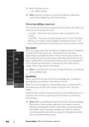
... to overlay Structure logs on available memory in the files browser. When increasing the search range, the ping speed of the StructureScan transducer is reduced, but only one StructureMap of interest on a previous scanned area. Ú Note: When saved files are required, ...StructureMap (*.smf) format. Select Structure source - If there is lost. Saved mode is available on separate memory cards. 94 StructureMap | HDS Carbon Operator Manual Saved files When Saved files are connected. These are recorded StructureScan (*.sl2 or *.sl3) data that are displayed. StructureMap ...
... to overlay Structure logs on available memory in the files browser. When increasing the search range, the ping speed of the StructureScan transducer is reduced, but only one StructureMap of interest on a previous scanned area. Ú Note: When saved files are required, ...StructureMap (*.smf) format. Select Structure source - If there is lost. Saved mode is available on separate memory cards. 94 StructureMap | HDS Carbon Operator Manual Saved files When Saved files are connected. These are recorded StructureScan (*.sl2 or *.sl3) data that are displayed. StructureMap ...

Operators Manual EN
Page 97
... resolution, while 455 kHz has greater depth and range coverage. Frequency Sets the transducer frequency used as the source. Structure options You adjust the StructureMap settings from the screen and begins showing only the most current data. StructureMap | HDS Carbon Operator Manual 97 With minimum transparency settings, the chart details are greyed. If...
... resolution, while 455 kHz has greater depth and range coverage. Frequency Sets the transducer frequency used as the source. Structure options You adjust the StructureMap settings from the screen and begins showing only the most current data. StructureMap | HDS Carbon Operator Manual 97 With minimum transparency settings, the chart details are greyed. If...

Installation Manual EN
Page 9
... the contents 11 HDS Carbon box contents 12 Overview 12 The front panel and keys 14 Rear connections 14 Card reader 16 Installation 16 Mounting location 17 Viewing angle 17 Bracket mounting 19 Panel mounting 20 Mounting the transducer 20 Research 20 Select a transducer location 21 Attaching the transducer 22 Adjusting the transducer 24 Wiring 24...
... the contents 11 HDS Carbon box contents 12 Overview 12 The front panel and keys 14 Rear connections 14 Card reader 16 Installation 16 Mounting location 17 Viewing angle 17 Bracket mounting 19 Panel mounting 20 Mounting the transducer 20 Research 20 Select a transducer location 21 Attaching the transducer 22 Adjusting the transducer 24 Wiring 24...

Installation Manual EN
Page 20
... selection and installation are two of propeller and hull generated turbulence, while mounting the transducer as possible. 1 23 4 5 20 Mounting the transducer | HDS Carbon Installation Manual To function properly the transducer must be in the water at cruising speed, watch the water flow behind the boat to the center of the propeller(s) • With the...
... selection and installation are two of propeller and hull generated turbulence, while mounting the transducer as possible. 1 23 4 5 20 Mounting the transducer | HDS Carbon Installation Manual To function properly the transducer must be in the water at cruising speed, watch the water flow behind the boat to the center of the propeller(s) • With the...

Installation Manual EN
Page 21
...on the hull can create large amounts of turbulence at higher speeds. Attaching the transducer The transducer should be installed parallel with strakes or ribs on these . Mounting the transducer | HDS Carbon Installation Manual 21 undisturbed water flow 5 Planing strake - The unit could also... to port (left) of propeller 2 Conventional clockwise propeller rotation 3 Avoid mounting within 7.5 cm (3") to the engine. Ú Note: If the transducer is of random lines or dots. avoid mounting behind here Ú Note: Reverse the distance guides (1 & 3) from propeller where engine is not ...
...on the hull can create large amounts of turbulence at higher speeds. Attaching the transducer The transducer should be installed parallel with strakes or ribs on these . Mounting the transducer | HDS Carbon Installation Manual 21 undisturbed water flow 5 Planing strake - The unit could also... to port (left) of propeller 2 Conventional clockwise propeller rotation 3 Avoid mounting within 7.5 cm (3") to the engine. Ú Note: If the transducer is of random lines or dots. avoid mounting behind here Ú Note: Reverse the distance guides (1 & 3) from propeller where engine is not ...

Installation Manual EN
Page 22
...ladder cannot snag the cable. Hold the transducer with speed, it may be possible to suit fasteners. Ú Note: Check that may be damaged by adjusting the angle of the transducer. 22 Mounting the transducer | HDS Carbon Installation Manual Drill pilot holes to eliminate ...these by drilling. Ú Note: Ensure the entire bottom surface of the transducer hangs at regular intervals using supplied stainless steel fasteners....
...ladder cannot snag the cable. Hold the transducer with speed, it may be possible to suit fasteners. Ú Note: Check that may be damaged by adjusting the angle of the transducer. 22 Mounting the transducer | HDS Carbon Installation Manual Drill pilot holes to eliminate ...these by drilling. Ú Note: Ensure the entire bottom surface of the transducer hangs at regular intervals using supplied stainless steel fasteners....

Installation Manual EN
Page 23
If performance does not improve with tilting, try adjusting the height of the transducer relative to the transom of the transom. If the transducer is tilted too far in either direction does not perform well; Mounting the transducer | HDS Carbon Installation Manual 23 Ú Note: A transducer that is too high it may be seeing cavitation caused by the trailing edge of the boat. missing targets, or losing the bottom at speed.
If performance does not improve with tilting, try adjusting the height of the transducer relative to the transom of the transom. If the transducer is tilted too far in either direction does not perform well; Mounting the transducer | HDS Carbon Installation Manual 23 Ú Note: A transducer that is too high it may be seeing cavitation caused by the trailing edge of the boat. missing targets, or losing the bottom at speed.

Installation Manual EN
Page 26
...plugged in standby mode, never transmit mode, when triggered by the accessory wake up line 7 Vessel's 12 V DC supply Transducer connection The unit has internal CHIRP, Broadband, StructureScan, TotalScan and ForwardScan sonar. The 9-pin black StructureScan connector can be ... POWER A 1 POWER B 2 3 4 5 6 +_ 7 A Power connection to unit on the left B Power connection to unit on page 14. 26 Wiring | HDS Carbon Installation Manual For connector location, refer to the embossed labeling on the unit or the section "Rear connections" on the right 1 Power cable connectors to...
...plugged in standby mode, never transmit mode, when triggered by the accessory wake up line 7 Vessel's 12 V DC supply Transducer connection The unit has internal CHIRP, Broadband, StructureScan, TotalScan and ForwardScan sonar. The 9-pin black StructureScan connector can be ... POWER A 1 POWER B 2 3 4 5 6 +_ 7 A Power connection to unit on the left B Power connection to unit on page 14. 26 Wiring | HDS Carbon Installation Manual For connector location, refer to the embossed labeling on the unit or the section "Rear connections" on the right 1 Power cable connectors to...

Installation Manual EN
Page 27
... RX5 Shield Color Blue/White Blue Orange/White Orange Bare Ethernet expansion device Connection of ports. Wiring | HDS Carbon Installation Manual 27 Ú Note: The connector attached to the transducer cable is equipped with an Ethernet port, which allows connecting the unit to your network using a 7-pin... to 9-pin adaptor cable. Refer to secure. Ú Note: A 7-pin transducer cable can be added to provide the required number of network devices can be inserted in one orientation. Once inserted, turn locking collar to...
... RX5 Shield Color Blue/White Blue Orange/White Orange Bare Ethernet expansion device Connection of ports. Wiring | HDS Carbon Installation Manual 27 Ú Note: The connector attached to the transducer cable is equipped with an Ethernet port, which allows connecting the unit to your network using a 7-pin... to 9-pin adaptor cable. Refer to secure. Ú Note: A 7-pin transducer cable can be added to provide the required number of network devices can be inserted in one orientation. Once inserted, turn locking collar to...


