
HALO 20 20 and 24 Installation Manual
Page 5
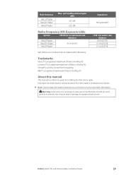
Preface | Halo20, 20+ and 24 Dome Radars Installation Manual | 5 Halo Antennas Halo 20 Radar Halo20+ Radar Halo24 Radar Max. Lowrance® is used by an independent laboratory. Simrad® is a registered trademark of injury and/or damage to equipment/personnel. Important text that they .... B&G® is emphasized as measured by license from the reader is a registered trademark of Navico Holding AS. Trademarks Navico® is a reference guide for installing the Halo dome radar. About this manual This manual is a registered trademark of Navico Holding AS.
Preface | Halo20, 20+ and 24 Dome Radars Installation Manual | 5 Halo Antennas Halo 20 Radar Halo20+ Radar Halo24 Radar Max. Lowrance® is used by an independent laboratory. Simrad® is a registered trademark of injury and/or damage to equipment/personnel. Important text that they .... B&G® is emphasized as measured by license from the reader is a registered trademark of Navico Holding AS. Trademarks Navico® is a reference guide for installing the Halo dome radar. About this manual This manual is a registered trademark of Navico Holding AS.
HALO 20 20 and 24 Installation Manual
Page 6
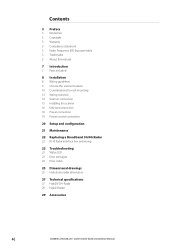
... Power control connection 20 Setup and configuration 21 Maintenance 22 Replacing a Broadband 3G/4G Radar 22 RI-10 Radar interface box and wiring 23 Troubleshooting 23 Status LED 23 Error messages 24 Error codes 25 Dimensional drawings 25 Halo dome radar dimensions 27 Technical specifications 27 Halo20/20+ Radar 28 Halo24 Radar 29 Accessories 6 | Contents | Halo20, 20+ and 24 Dome Radars Installation Manual
... Power control connection 20 Setup and configuration 21 Maintenance 22 Replacing a Broadband 3G/4G Radar 22 RI-10 Radar interface box and wiring 23 Troubleshooting 23 Status LED 23 Error messages 24 Error codes 25 Dimensional drawings 25 Halo dome radar dimensions 27 Technical specifications 27 Halo20/20+ Radar 28 Halo24 Radar 29 Accessories 6 | Contents | Halo20, 20+ and 24 Dome Radars Installation Manual
HALO 20 20 and 24 Installation Manual
Page 7
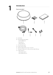
1 Introduction Parts included A B bbbbaaaannnnddddgggg....ccccoooommmm EEEENNNNGGGGLLLLIIIISSSSHHHHIIIInnnnssssttttaaaallllllllaaaattttiiiioooonnnn MMMMaaaannnnuuuuaaaallll C D E F G A Halo Radar B Mounting bolts and washers Hex bolt (M8x30), 4x Flat washer, 4x Spring washer, 4x C Documentation pack D Interconnection cable E Ethernet adapter RJ45 to 5-pin, 1.5m (4.9 ft) F Waterproof cable boot for interconnection cable RJ45 plug G Cable retainer kit Cable retainer clip, 2x Screw (Phillips drive), 4x Introduction | Halo20, 20+ and 24 Dome Radars Installation Manual | 7
1 Introduction Parts included A B bbbbaaaannnnddddgggg....ccccoooommmm EEEENNNNGGGGLLLLIIIISSSSHHHHIIIInnnnssssttttaaaallllllllaaaattttiiiioooonnnn MMMMaaaannnnuuuuaaaallll C D E F G A Halo Radar B Mounting bolts and washers Hex bolt (M8x30), 4x Flat washer, 4x Spring washer, 4x C Documentation pack D Interconnection cable E Ethernet adapter RJ45 to 5-pin, 1.5m (4.9 ft) F Waterproof cable boot for interconnection cable RJ45 plug G Cable retainer kit Cable retainer clip, 2x Screw (Phillips drive), 4x Introduction | Halo20, 20+ and 24 Dome Radars Installation Manual | 7
HALO 20 20 and 24 Installation Manual
Page 8
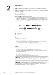
... the voltage of the power supply is left on or turned on page 22. If power is compatible with the unit. 8 | Installation | Halo20, 20+ and 24 Dome Radars Installation Manual BAB AC B B A Mouse line B Electrical tape C Cable tie Do: • make drip and...always be sure to "Replacing a Broadband 3G/4G Radar" on during the installation, fire, electrical shock, or other serious injury may occur. ! 2 Installation ¼ Note: The Halo Radar is transferred to the stronger outer jacket of the radar interconnection cable so that allows water to flow down...
... the voltage of the power supply is left on or turned on page 22. If power is compatible with the unit. 8 | Installation | Halo20, 20+ and 24 Dome Radars Installation Manual BAB AC B B A Mouse line B Electrical tape C Cable tie Do: • make drip and...always be sure to "Replacing a Broadband 3G/4G Radar" on during the installation, fire, electrical shock, or other serious injury may occur. ! 2 Installation ¼ Note: The Halo Radar is transferred to the stronger outer jacket of the radar interconnection cable so that allows water to flow down...
HALO 20 20 and 24 Installation Manual
Page 9
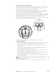
...Installation | Halo20, 20+ and 24 Dome Radars Installation Manual | 9 Higher installation height also reduces the ability of the radar to elevate the scanner so the radar beam clears the roof line. If you think you'll need a longer cable, consult your radar is sufficient for the majority of the radar...scanner should, where possible, be subjected to lamps or exhaust outlets. Warning: For dual radar installations, ensure the Halo Radar is likely to detect targets greatly depends on the position of the radar ! The ideal location for roof mounting" on a pedestal or base, ensure that ...
...Installation | Halo20, 20+ and 24 Dome Radars Installation Manual | 9 Higher installation height also reduces the ability of the radar to elevate the scanner so the radar beam clears the roof line. If you think you'll need a longer cable, consult your radar is sufficient for the majority of the radar...scanner should, where possible, be subjected to lamps or exhaust outlets. Warning: For dual radar installations, ensure the Halo Radar is likely to detect targets greatly depends on the position of the radar ! The ideal location for roof mounting" on a pedestal or base, ensure that ...
HALO 20 20 and 24 Installation Manual
Page 10
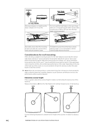
... size of the hard top of the vessel, it is 0.7 m (2.3 ft). Pulse Radar STBY Do not install the Halo Radar on power boats that the mounting location provides the scanner with a clear view all round the vessel. Installation | Halo20, 20+ and 24 Dome Radars Installation Manual If installed on the same beam plane as per Optimum performance section, else performance...
... size of the hard top of the vessel, it is 0.7 m (2.3 ft). Pulse Radar STBY Do not install the Halo Radar on power boats that the mounting location provides the scanner with a clear view all round the vessel. Installation | Halo20, 20+ and 24 Dome Radars Installation Manual If installed on the same beam plane as per Optimum performance section, else performance...
HALO 20 20 and 24 Installation Manual
Page 11
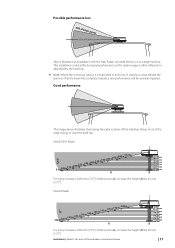
... top. This installation could suffer decreased performance as the radar energy is either reflected or absorbed by the hard top. ¼ Note: Where the mounting surface is constructed of any form of beam power Above illustrates an installation with the Halo Radar mounted directly on to clear the hard top. Halo20/20+ Radar 3.0 m2.80... m2.60 m2.40 m2.20 m2.00 m1.80 m1.60 m1.40 m1.20 m1.00 m0.80 m 0.55 m A 0 mm 60 mm ...
... top. This installation could suffer decreased performance as the radar energy is either reflected or absorbed by the hard top. ¼ Note: Where the mounting surface is constructed of any form of beam power Above illustrates an installation with the Halo Radar mounted directly on to clear the hard top. Halo20/20+ Radar 3.0 m2.80... m2.60 m2.40 m2.20 m2.00 m1.80 m1.60 m1.40 m1.20 m1.00 m0.80 m 0.55 m A 0 mm 60 mm ...
HALO 20 20 and 24 Installation Manual
Page 13
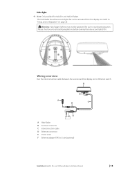
... a blue accent light that can be approved for Halo20+ and Halo24 Radars. Please check your boating location. Warning: Halo Radar's lighting may not be activated from the display unit. Halo light ¼ Note: Only available for use in your local... the scanner and the display unit or Ethernet switch. A B F D C E A Halo Radar B Scanner connector C Interconnection cable D Ethernet connector E Power wires F Ethernet adapter RJ45 to "Setup and configuration" on page 20. ! Refer to 5-pin (optional) Installation | Halo20, 20+ and 24 Dome Radars Installation Manual | 13
... a blue accent light that can be approved for Halo20+ and Halo24 Radars. Please check your boating location. Warning: Halo Radar's lighting may not be activated from the display unit. Halo light ¼ Note: Only available for use in your local... the scanner and the display unit or Ethernet switch. A B F D C E A Halo Radar B Scanner connector C Interconnection cable D Ethernet connector E Power wires F Ethernet adapter RJ45 to "Setup and configuration" on page 20. ! Refer to 5-pin (optional) Installation | Halo20, 20+ and 24 Dome Radars Installation Manual | 13
HALO 20 20 and 24 Installation Manual
Page 20
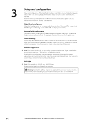
... light level of the LED accent light. ! Make the following settings before turning the blue accent lights ON. 20 | Setup and configuration | Halo20, 20+ and 24 Dome Radars Installation Manual Sector blanking Used to Auto. Warning: Halo Radar's lighting may occur if this control is not adjusted correctly. Adjust bearing alignment Aligns the heading marker on the...
... light level of the LED accent light. ! Make the following settings before turning the blue accent lights ON. 20 | Setup and configuration | Halo20, 20+ and 24 Dome Radars Installation Manual Sector blanking Used to Auto. Warning: Halo Radar's lighting may occur if this control is not adjusted correctly. Adjust bearing alignment Aligns the heading marker on the...
HALO 20 20 and 24 Installation Manual
Page 22
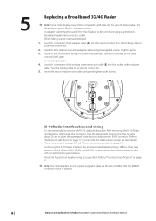
...(A) into the socket on page 27. ¼ Note: Halo dome radars do not require navigation data via the scanner adaptor cable, with Halo 20, 20+ and 24 dome radars. Swivel the second retainer over the RJ45 connector. Install the second retainer using the supplied screws. Turn the locking ...channel is connected via Simnet or NMEA 2000 for MARPA or Velocity Track to operate. 22 | Replacing a Broadband 3G/4G Radar | Halo20, 20+ and 24 Dome Radars Installation Manual Turn the locking collar to "Waterproof cable boot" on page 19. Refer to secure the connector. 2. Check the...
...(A) into the socket on page 27. ¼ Note: Halo dome radars do not require navigation data via the scanner adaptor cable, with Halo 20, 20+ and 24 dome radars. Swivel the second retainer over the RJ45 connector. Install the second retainer using the supplied screws. Turn the locking ...channel is connected via Simnet or NMEA 2000 for MARPA or Velocity Track to operate. 22 | Replacing a Broadband 3G/4G Radar | Halo20, 20+ and 24 Dome Radars Installation Manual Turn the locking collar to "Waterproof cable boot" on page 19. Refer to secure the connector. 2. Check the...

HALO 20 20 and 24 Installation Manual
Page 25
A 7 Dimensional drawings Halo dome radar dimensions B C D Key Halo20/20+ Radar A 223.0 mm (8.78") B 510.0 mm (20.08") C 233.0 mm (9.17") D 141.5 mm (5.57") Dimensions Halo24 Radar 225 mm (8.9") 610 mm (24") 233.0 mm (9.17") 141.5 mm (5.57") Broadband 3G/4G Radar 280 mm (11.02") 488.6 mm (19.24") 233.0 mm (9.17") 141.5 mm (5.57") ¼ Note: The bolt holes are located in the same position for each radar. Dimensional drawings | Halo20, 20+ and 24 Dome Radars Installation Manual | 25
A 7 Dimensional drawings Halo dome radar dimensions B C D Key Halo20/20+ Radar A 223.0 mm (8.78") B 510.0 mm (20.08") C 233.0 mm (9.17") D 141.5 mm (5.57") Dimensions Halo24 Radar 225 mm (8.9") 610 mm (24") 233.0 mm (9.17") 141.5 mm (5.57") Broadband 3G/4G Radar 280 mm (11.02") 488.6 mm (19.24") 233.0 mm (9.17") 141.5 mm (5.57") ¼ Note: The bolt holes are located in the same position for each radar. Dimensional drawings | Halo20, 20+ and 24 Dome Radars Installation Manual | 25

HALO 20 20 and 24 Installation Manual
Page 26
Halo dome radar bottom view C C D D B C C A Key Description A Cable entry area B Cable retention channel C Bolt hole M8 x 30 mm D LED accent light* * Only available for Halo20+ and Halo24 Radars. 26 | Dimensional drawings | Halo20, 20+ and 24 Dome Radars Installation Manual
Halo dome radar bottom view C C D D B C C A Key Description A Cable entry area B Cable retention channel C Bolt hole M8 x 30 mm D LED accent light* * Only available for Halo20+ and Halo24 Radars. 26 | Dimensional drawings | Halo20, 20+ and 24 Dome Radars Installation Manual


