Getting Started EN
Page 27
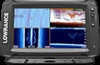
Setting up the image Use the Sonar menu options to the normal Sonar menu. Sonar | ELITE Ti Getting Started 27 Select Clear cursor to return to set too low. If you will not be displayed if Sensitivity is active, some options on ... The range setting determines the water depth that is visible on the Sonar menu are replaced with cursor mode features. Available frequencies depend on the transducer model that is connected. Ú Note: This unit cannot operate CHIRP frequencies and SideScan at the same time by panning the image. To resume normal...
Setting up the image Use the Sonar menu options to the normal Sonar menu. Sonar | ELITE Ti Getting Started 27 Select Clear cursor to return to set too low. If you will not be displayed if Sensitivity is active, some options on ... The range setting determines the water depth that is visible on the Sonar menu are replaced with cursor mode features. Available frequencies depend on the transducer model that is connected. Ú Note: This unit cannot operate CHIRP frequencies and SideScan at the same time by panning the image. To resume normal...

Getting Started EN
Page 29
...range. When you select the record option in manual mode, you might not receive any depth readings, or you might receive incorrect depth information. Sonar | ELITE Ti Getting Started 29 By default, the ping speed is out of sonar data. Ú Note: In certain conditions it onto a card inserted into the ... for specific fishing conditions. Recorded StructureScan data can save it may be necessary to adjust the scroll speed to start and stop recording of transducer range. Ping speed Ping speed controls the rate the transducer transmits the signal into the unit's card reader.
...range. When you select the record option in manual mode, you might not receive any depth readings, or you might receive incorrect depth information. Sonar | ELITE Ti Getting Started 29 By default, the ping speed is out of sonar data. Ú Note: In certain conditions it onto a card inserted into the ... for specific fishing conditions. Recorded StructureScan data can save it may be necessary to adjust the scroll speed to start and stop recording of transducer range. Ping speed Ping speed controls the rate the transducer transmits the signal into the unit's card reader.

Getting Started EN
Page 30
...turn on StructureScan Left/Right view, you will not be set up as an overlay to the traditional Sonar image. 30 StructureScan | ELITE Ti Getting Started The StructureScan image The view The StructureScan panel can also be added as a DownScan image, or showing left/right side scanning...resolution, picture-like image of structure and fish directly below your boat. The StructureScan page is accessed from the Home page when the TotalScan transducer is connected. Ú Note: This unit cannot operate CHIRP frequencies and SideScan at the same time. StructureScan HD provides a wide coverage in...
...turn on StructureScan Left/Right view, you will not be set up as an overlay to the traditional Sonar image. 30 StructureScan | ELITE Ti Getting Started The StructureScan image The view The StructureScan panel can also be added as a DownScan image, or showing left/right side scanning...resolution, picture-like image of structure and fish directly below your boat. The StructureScan page is accessed from the Home page when the TotalScan transducer is connected. Ú Note: This unit cannot operate CHIRP frequencies and SideScan at the same time. StructureScan HD provides a wide coverage in...

Getting Started EN
Page 32
... option when you use Auto contrast. Range The range setting determines the water depth and SideScan range that you want to turn off the StructureScan transducer, but not turn off the unit. 32 StructureScan | ELITE Ti Getting Started
... option when you use Auto contrast. Range The range setting determines the water depth and SideScan range that you want to turn off the StructureScan transducer, but not turn off the unit. 32 StructureScan | ELITE Ti Getting Started

Getting Started EN
Page 33
... be added to the image to make it easier to start and stop recording of the transducer installation. Recording StructureScan data Select the Log data menu option to estimate depth (Downscan) and distance (SideScan). StructureScan | ELITE Ti Getting Started 33 The surface clarity option reduces surface clutter by decreasing the sensitivity of the...
... be added to the image to make it easier to start and stop recording of the transducer installation. Recording StructureScan data Select the Log data menu option to estimate depth (Downscan) and distance (SideScan). StructureScan | ELITE Ti Getting Started 33 The surface clarity option reduces surface clutter by decreasing the sensitivity of the...
Installation Manual EN
Page 9
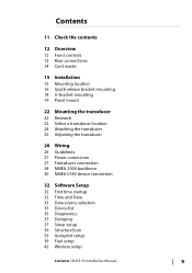
... mounting 18 U-bracket mounting 19 Panel mount 22 Mounting the transducer 22 Research 22 Select a transducer location 24 Attaching the transducer 25 Adjusting the transducer 26 Wiring 26 Guidelines 27 Power connection 27 Transducer connection 28 NMEA 2000 backbone 30 NMEA 0183 device connection 32... Software Setup 32 First time startup 32 Time and Date 33 Data source selection 35 Device list 35 Diagnostics 37 Damping 37 Sonar setup 39 StructureScan 39 Autopilot setup 39 Fuel setup 42 Wireless setup Contents | ELITE Ti...
... mounting 18 U-bracket mounting 19 Panel mount 22 Mounting the transducer 22 Research 22 Select a transducer location 24 Attaching the transducer 25 Adjusting the transducer 26 Wiring 26 Guidelines 27 Power connection 27 Transducer connection 28 NMEA 2000 backbone 30 NMEA 0183 device connection 32... Software Setup 32 First time startup 32 Time and Date 33 Data source selection 35 Device list 35 Diagnostics 37 Damping 37 Sonar setup 39 StructureScan 39 Autopilot setup 39 Fuel setup 42 Wireless setup Contents | ELITE Ti...
Installation Manual EN
Page 11
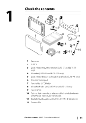
... 12 11 1 Sun cover 2 ELITE Ti 3 Quick release mounting bracket (ELITE-5Ti and ELITE-7Ti only) 4 U bracket (ELITE-9Ti and ELITE-12Ti only) 5 Quick release bracket locking bolt and knob. (ELITE-7Ti only) 6 Documentation pack 7 Fuse holder (ATC blade) 8 U bracket knobs (2x) (ELITE-9Ti and ELITE-12Ti only) 9 Fuse (3 amp) 10 7-pin to 9-pin transducer adapter cable. Included only with...
... 12 11 1 Sun cover 2 ELITE Ti 3 Quick release mounting bracket (ELITE-5Ti and ELITE-7Ti only) 4 U bracket (ELITE-9Ti and ELITE-12Ti only) 5 Quick release bracket locking bolt and knob. (ELITE-7Ti only) 6 Documentation pack 7 Fuse holder (ATC blade) 8 U bracket knobs (2x) (ELITE-9Ti and ELITE-12Ti only) 9 Fuse (3 amp) 10 7-pin to 9-pin transducer adapter cable. Included only with...

Installation Manual EN
Page 22
... rotation of the vessel as possible. 22 Mounting the transducer | ELITE Ti Installation Manual Warning: Read all times, and in Sonar installation. Transducer location selection and installation are provided with the smoothest flow (least bubbles) Select a transducer location The primary aim is moving. 4 Mounting the transducer This chapter provides instructions for installing the StructureScan HD and...
... rotation of the vessel as possible. 22 Mounting the transducer | ELITE Ti Installation Manual Warning: Read all times, and in Sonar installation. Transducer location selection and installation are provided with the smoothest flow (least bubbles) Select a transducer location The primary aim is moving. 4 Mounting the transducer This chapter provides instructions for installing the StructureScan HD and...

Installation Manual EN
Page 23
... (1 & 3) from propeller where engine is of counterclockwise configuration. Ú Note: Vessels with strakes or ribs on these . A good transducer location on the hull can create large amounts of turbulence at higher speeds. Mounting the transducer | ELITE Ti Installation Manual 23 undisturbed water flow 5 Planing strake - 1 23 4 5 1 Avoid mounting within 1 m (3.3') to port (left) of propeller...
... (1 & 3) from propeller where engine is of counterclockwise configuration. Ú Note: Vessels with strakes or ribs on these . A good transducer location on the hull can create large amounts of turbulence at higher speeds. Mounting the transducer | ELITE Ti Installation Manual 23 undisturbed water flow 5 Planing strake - 1 23 4 5 1 Avoid mounting within 1 m (3.3') to port (left) of propeller...

Installation Manual EN
Page 24
... drilling points in the middle of the boat and trace the slotted screw hole locations (two on the 83/200 KHz transducer, and four on the other side of the mounting surface that may be installed parallel with bracket up to the transom ...Note: Check that there is nothing on the 50/200 KHz transducer). Drill a 25 mm (1") hole above the waterline, large enough to transom, using supplied stainless steel fasteners. Attaching the transducer The transducer should be damaged by drilling. Attach transducer to pass the plug through. 24 Mounting the transducer | ELITE Ti Installation Manual
... drilling points in the middle of the boat and trace the slotted screw hole locations (two on the 83/200 KHz transducer, and four on the other side of the mounting surface that may be installed parallel with bracket up to the transom ...Note: Check that there is nothing on the 50/200 KHz transducer). Drill a 25 mm (1") hole above the waterline, large enough to transom, using supplied stainless steel fasteners. Attaching the transducer The transducer should be damaged by drilling. Attach transducer to pass the plug through. 24 Mounting the transducer | ELITE Ti Installation Manual
Installation Manual EN
Page 25
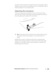
... tilted too far in either direction does not perform well; Mounting the transducer | ELITE Ti Installation Manual 25 missing targets, or losing the bottom at regular intervals using cable P clips or saddles and ensure that is too high it ... may be seeing cavitation caused by adjusting the angle of the transducer. Ú Note: A transducer that moving , which worsen with tilting, try adjusting the height of the transducer relative to eliminate these by the trailing edge of the boat. Adjusting the transducer If the sonar image shows interference lines on the screen when...
... tilted too far in either direction does not perform well; Mounting the transducer | ELITE Ti Installation Manual 25 missing targets, or losing the bottom at regular intervals using cable P clips or saddles and ensure that is too high it ... may be seeing cavitation caused by adjusting the angle of the transducer. Ú Note: A transducer that moving , which worsen with tilting, try adjusting the height of the transducer relative to eliminate these by the trailing edge of the boat. Adjusting the transducer If the sonar image shows interference lines on the screen when...
Installation Manual EN
Page 27
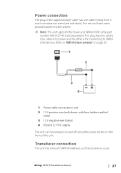
... wires provide power into the system. Ú Note: The unit supports the Power and NMEA 0183 Cable, part number 000-0127-49 (sold separately). Transducer connection The unit has internal CHIRP, Broadband, and StructureScan sonar. Wiring | ELITE Ti Installation Manual 27 Power connection The plug of the unit. This plug has two cables.
... wires provide power into the system. Ú Note: The unit supports the Power and NMEA 0183 Cable, part number 000-0127-49 (sold separately). Transducer connection The unit has internal CHIRP, Broadband, and StructureScan sonar. Wiring | ELITE Ti Installation Manual 27 Power connection The plug of the unit. This plug has two cables.
Installation Manual EN
Page 28
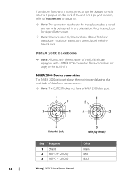
...NMEA 2000 backbone Ú Note: All units, with the exception of the ELITE-5Ti, are included with a NMEA 2000 connector. This section does not apply to the transducer cable is keyed, and can be inserted in one orientation. NMEA 2000 Device...3 NET-C (- 12 VDC) Color Drain Red Black 28 Wiring | ELITE Ti Installation Manual Once inserted, turn locking collar to secure. Ú Note: StructureScan HD, StructureScan 3D and TotalScan transducer installation instructions are equipped with the transducers. Transducers fitted with a 9 pin connector can only be plugged directly into the...
...NMEA 2000 backbone Ú Note: All units, with the exception of the ELITE-5Ti, are included with a NMEA 2000 connector. This section does not apply to the transducer cable is keyed, and can be inserted in one orientation. NMEA 2000 Device...3 NET-C (- 12 VDC) Color Drain Red Black 28 Wiring | ELITE Ti Installation Manual Once inserted, turn locking collar to secure. Ú Note: StructureScan HD, StructureScan 3D and TotalScan transducer installation instructions are equipped with the transducers. Transducers fitted with a 9 pin connector can only be plugged directly into the...

Installation Manual EN
Page 37
... Setup | ELITE Ti Installation Manual 37 Keel offset All transducers measure water depth from the transducer to make the information appear more stable. Fast Packet Errors Cumulative counter of network nodes (devices). As a result, water depth readings do not account for the distance from the transducer to the ... (for heading, course over ground, speed over ground, apparent wind, true wind, boat speed, depth, and tide sourced from the transducer to 32 frames. The entire message will be resolved by correcting termination, reducing backbone or drop lengths, or reducing the number of any...
... Setup | ELITE Ti Installation Manual 37 Keel offset All transducers measure water depth from the transducer to make the information appear more stable. Fast Packet Errors Cumulative counter of network nodes (devices). As a result, water depth readings do not account for the distance from the transducer to the ... (for heading, course over ground, speed over ground, apparent wind, true wind, boat speed, depth, and tide sourced from the transducer to 32 frames. The entire message will be resolved by correcting termination, reducing backbone or drop lengths, or reducing the number of any...

Installation Manual EN
Page 38
... built-in temperature sensors, the temperature reading may be inaccurate or not available at all if the wrong transducer is selected. Transducer temperature sensors are 38 Software Setup | ELITE Ti Installation Manual If, for localized influences to the measured temperature. A A Keel offset, for example: - 0.3 m (- 1 ft) Before setting the keel offset, measure the distance from...
... built-in temperature sensors, the temperature reading may be inaccurate or not available at all if the wrong transducer is selected. Transducer temperature sensors are 38 Software Setup | ELITE Ti Installation Manual If, for localized influences to the measured temperature. A A Keel offset, for example: - 0.3 m (- 1 ft) Before setting the keel offset, measure the distance from...
Installation Manual EN
Page 39
... the utility, a Navico Fuel Flow sensor, or a NMEA 2000 engine adaptor cable/gateway with transducer to the engine manufacturer or dealer for information on page 33. Software Setup | ELITE Ti Installation Manual 39 given for the same model transducer, refer to paperwork supplied with Navico Fuel Data Storage device must be used to "Data...
... the utility, a Navico Fuel Flow sensor, or a NMEA 2000 engine adaptor cable/gateway with transducer to the engine manufacturer or dealer for information on page 33. Software Setup | ELITE Ti Installation Manual 39 given for the same model transducer, refer to paperwork supplied with Navico Fuel Data Storage device must be used to "Data...
Installation Manual EN
Page 55
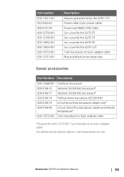
...pin power cable) Power and NMEA 0183 Cable Sun cover for the ELITE-5Ti Sun cover for the ELITE-7Ti Sun cover for the ELITE-9Ti Sun cover for the ELITE-12Ti 7-pin transducer to 9-pin adapter cable Blue and black corner detail clips Sonar ...transducer, 83/200 kHz* 000-0106-73 In-hull shoot-thru transducer, depth only* 000-0106-89 In-hull, shoot-thru transducer, depth and remote temperature* 000-12572-001 7-pin transducer to 9-pin adapter cable * Require the 000-12572-001 7-pin transducer to 9-pin adapter cable For additional transducer options, visit www.lowrance.com Accessories | ELITE Ti...
...pin power cable) Power and NMEA 0183 Cable Sun cover for the ELITE-5Ti Sun cover for the ELITE-7Ti Sun cover for the ELITE-9Ti Sun cover for the ELITE-12Ti 7-pin transducer to 9-pin adapter cable Blue and black corner detail clips Sonar ...transducer, 83/200 kHz* 000-0106-73 In-hull shoot-thru transducer, depth only* 000-0106-89 In-hull, shoot-thru transducer, depth and remote temperature* 000-12572-001 7-pin transducer to 9-pin adapter cable * Require the 000-12572-001 7-pin transducer to 9-pin adapter cable For additional transducer options, visit www.lowrance.com Accessories | ELITE Ti...

Installation Manual EN
Page 67
... Import 53 Date format 32 Device list 35 Device name 33 DHCP Probe, wireless tool 47 Diagnostics 35 Dimensional drawings ELITE-12Ti 65 ELITE-5Ti 64 ELITE-7Ti 64 ELITE-9Ti 65 E Echosounder Noise, adjust transducer 25 Engines Setup 39 Export Region 52 Database backup 52 Database export settings 53 Waypoints, Routes, and Tracks 52...
... Import 53 Date format 32 Device list 35 Device name 33 DHCP Probe, wireless tool 47 Diagnostics 35 Dimensional drawings ELITE-12Ti 65 ELITE-5Ti 64 ELITE-7Ti 64 ELITE-9Ti 65 E Echosounder Noise, adjust transducer 25 Engines Setup 39 Export Region 52 Database backup 52 Database export settings 53 Waypoints, Routes, and Tracks 52...
Installation Manual EN
Page 68
... setup 37 StructureScan 39 T Tablet connection GoFree, wireless 42 Technical specifications 62 Time Vessel location, format 32 Tools Wireless fault finding 46 Touchscreen Calibration 50 Transducer type 38 Transducer Adjust to reduce noise 25 Attaching 24 Location 22 Mounting 22 Prepare for installation 22 U Upgrade Software 51 Upgrade MEA 2000 devices 51
... setup 37 StructureScan 39 T Tablet connection GoFree, wireless 42 Technical specifications 62 Time Vessel location, format 32 Tools Wireless fault finding 46 Touchscreen Calibration 50 Transducer type 38 Transducer Adjust to reduce noise 25 Attaching 24 Location 22 Mounting 22 Prepare for installation 22 U Upgrade Software 51 Upgrade MEA 2000 devices 51

Operator Manual EN
Page 59
.... Auto sensitivity can help differentiate softer targets from harder ones. Minor adjustments can view two frequencies at the same time. Sonar | ELITE Ti Operator Manual 59 Colorline Allows the user to adjust the colors of the slider bar. Ú Note: Setting a custom range puts... structures on StructureScan Left/Right view, you may not be able to use the CHIRP sonar. Frequency The unit supports several transducer frequencies. Too much detail clutters the screen. Adjusting Sensitivity and Colorline Select the Sensitivity or Colorline menu options in manual mode....
.... Auto sensitivity can help differentiate softer targets from harder ones. Minor adjustments can view two frequencies at the same time. Sonar | ELITE Ti Operator Manual 59 Colorline Allows the user to adjust the colors of the slider bar. Ú Note: Setting a custom range puts... structures on StructureScan Left/Right view, you may not be able to use the CHIRP sonar. Frequency The unit supports several transducer frequencies. Too much detail clutters the screen. Adjusting Sensitivity and Colorline Select the Sensitivity or Colorline menu options in manual mode....


