
SL595 Manual
Page 1
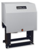
GLCONTROLLER BOARD MODEL SL585 HEAVY DUTY SLIDE GATE OPERATOR 2 YEAR WARRANTY Serial located on electrical box cover) Installation Date MODEL SL595 HEAVY DUTY, HARSH ENVIRONMENT SLIDE GATE OPERATOR MODELS SL585 AND SL595 ARE FOR VEHICULAR PASSAGE GATES ONLY AND ARE NOT INTENDED FOR PEDESTRIAN PASSAGE GATE USE
GLCONTROLLER BOARD MODEL SL585 HEAVY DUTY SLIDE GATE OPERATOR 2 YEAR WARRANTY Serial located on electrical box cover) Installation Date MODEL SL595 HEAVY DUTY, HARSH ENVIRONMENT SLIDE GATE OPERATOR MODELS SL585 AND SL595 ARE FOR VEHICULAR PASSAGE GATES ONLY AND ARE NOT INTENDED FOR PEDESTRIAN PASSAGE GATE USE

SL595 Manual
Page 2
... 12 When you see this manual and follow all components were provided and received undamaged. Read them . Model SL585 33 Illustrated Parts - Model SL595 35 Illustrated Parts - The hazard may come from something Gate System Test Procedures 13 mechanical or from electric shock. AVERT Install Vent Plug 14 AVERTISSEMENT UL325 Entrapment Protection...
... 12 When you see this manual and follow all components were provided and received undamaged. Read them . Model SL585 33 Illustrated Parts - Model SL595 35 Illustrated Parts - The hazard may come from something Gate System Test Procedures 13 mechanical or from electric shock. AVERT Install Vent Plug 14 AVERTISSEMENT UL325 Entrapment Protection...

SL595 Manual
Page 3
OPERATOR DIMENSIONS AND HORSEPOWER CHART MODEL SL585 • 1/2 HP Motor Maximum Gate Speed - 11"/sec. (27.9 cm/sec.) Maximum Gate Weight - 1000 lbs. (453.6 kg) Maximum Cantilever Gate Width - 25 ft. (7.6 m) Maximum Overhead Roller Gate Width - 45 ft. (13.7 m) Maximum V-Track Gate Width - 35 ft. (10.7 m) 28.9" (73.4 cm) 27.5" (69.9 cm) 17.2" (43.7 cm) • 1 HP...
OPERATOR DIMENSIONS AND HORSEPOWER CHART MODEL SL585 • 1/2 HP Motor Maximum Gate Speed - 11"/sec. (27.9 cm/sec.) Maximum Gate Weight - 1000 lbs. (453.6 kg) Maximum Cantilever Gate Width - 25 ft. (7.6 m) Maximum Overhead Roller Gate Width - 45 ft. (13.7 m) Maximum V-Track Gate Width - 35 ft. (10.7 m) 28.9" (73.4 cm) 27.5" (69.9 cm) 17.2" (43.7 cm) • 1 HP...
SL595 Manual
Page 4
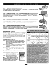
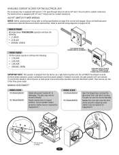
...dock area or other building servicing the general public. SAFETY ACCESSORY SELECTION All UL325 compliant LiftMaster gate operators will accept external entrapment protection devices to protect people from motorized gate systems. UL325 requires that the installation must have warning signs placed in a industrial ... for use in a commercial location or building such as a secondary protection. CLASS IV - A contact device such as a gate edge can be designed, arranged or configured to complete a proper installation you must have one primary means of entrapment protection and ...
...dock area or other building servicing the general public. SAFETY ACCESSORY SELECTION All UL325 compliant LiftMaster gate operators will accept external entrapment protection devices to protect people from motorized gate systems. UL325 requires that the installation must have warning signs placed in a industrial ... for use in a commercial location or building such as a secondary protection. CLASS IV - A contact device such as a gate edge can be designed, arranged or configured to complete a proper installation you must have one primary means of entrapment protection and ...
SL595 Manual
Page 5
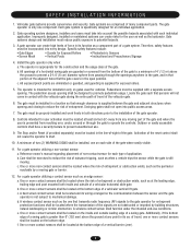
... sensors shall be located where the risk of entrapment or obstruction exists, such as a component part of application. e. A gate operator can create risks for an individual application. 2. Reference owner's manual regarding placement of non-contact sensor for vehicles. One... or more contact sensors shall be supplied with the vehicular gate during the entire path of travel , one component. b. c. The gate operator is intended for Exposed Rollers • Vertical Posts • Photoelectric Sensors • Instructional...
... sensors shall be located where the risk of entrapment or obstruction exists, such as a component part of application. e. A gate operator can create risks for an individual application. 2. Reference owner's manual regarding placement of non-contact sensor for vehicles. One... or more contact sensors shall be supplied with the vehicular gate during the entire path of travel , one component. b. c. The gate operator is intended for Exposed Rollers • Vertical Posts • Photoelectric Sensors • Instructional...

SL595 Manual
Page 6
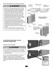
SUGGESTED ENTRAPMENT PROTECTION DEVICE LOCATIONS GATE SYSTEM (MASTER/SECOND SLIDE GATE) Open Edge Gate 2 Open Edge STREET Photo eyes for close cycle Gate 1 Close Edge Photo eyes for open cycle Run twisted wire from loop to operator Interrupt (Safety) Loop 4'T(y1p.2icmal) 4'T(y1p.2icmal) ...LOT Seal loops 1-1/2" (37 mm) Loop wire layer 1/4" (6 mm) or larger depending on loop wire size Photo eyes for open cycle GATE SYSTEM (COMMERCIAL SLIDE GATE) Telephone Entry System Open Edge Close Edge Photo eye for open cycle STREET 8' (2.4Inmt(eS)rarLufoepottyp) Photo eye for close cycle 4' (1.2...
SUGGESTED ENTRAPMENT PROTECTION DEVICE LOCATIONS GATE SYSTEM (MASTER/SECOND SLIDE GATE) Open Edge Gate 2 Open Edge STREET Photo eyes for close cycle Gate 1 Close Edge Photo eyes for open cycle Run twisted wire from loop to operator Interrupt (Safety) Loop 4'T(y1p.2icmal) 4'T(y1p.2icmal) ...LOT Seal loops 1-1/2" (37 mm) Loop wire layer 1/4" (6 mm) or larger depending on loop wire size Photo eyes for open cycle GATE SYSTEM (COMMERCIAL SLIDE GATE) Telephone Entry System Open Edge Close Edge Photo eye for open cycle STREET 8' (2.4Inmt(eS)rarLufoepottyp) Photo eye for close cycle 4' (1.2...
SL595 Manual
Page 7
... To prevent entrapment injuries, mount controls at ALL times. To prevent INJURY to prevent access through openings in the grill while the gate is not a chance of INJURY at any time without prior warning. Locate the pedestrian access where there is operating. This operator is... post or fence. These potential pinch-points should be guarded against at least Both Sides of the Exposed 6' (1.8 m) from the gate. Gate may travel. WARNING SIGN PLACEMENT ADVERTENCIA WARNING PRECAUCIÓN To prevent SERIOUS INJURY or DEATH from many fence suppliers. Also, Photo Beam...
... To prevent entrapment injuries, mount controls at ALL times. To prevent INJURY to prevent access through openings in the grill while the gate is not a chance of INJURY at any time without prior warning. Locate the pedestrian access where there is operating. This operator is... post or fence. These potential pinch-points should be guarded against at least Both Sides of the Exposed 6' (1.8 m) from the gate. Gate may travel. WARNING SIGN PLACEMENT ADVERTENCIA WARNING PRECAUCIÓN To prevent SERIOUS INJURY or DEATH from many fence suppliers. Also, Photo Beam...
SL595 Manual
Page 8
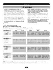
... that time the unit may result in SEVERE INJURY to persons and/or damage to operator. POWER WAIRITNGTIENSNTATLLIAOTINON Wiring Specifications (STRANDED COPPER WIRE) On a Dual Gate System, each unit must be installed on ITS OWN separate circuits. AVERTISSEMENT SINGLE PHASE WIRE GAUGE 6 115 Vac 230 Vac 230 Vac THREE PHASE 460...
... that time the unit may result in SEVERE INJURY to persons and/or damage to operator. POWER WAIRITNGTIENSNTATLLIAOTINON Wiring Specifications (STRANDED COPPER WIRE) On a Dual Gate System, each unit must be installed on ITS OWN separate circuits. AVERTISSEMENT SINGLE PHASE WIRE GAUGE 6 115 Vac 230 Vac 230 Vac THREE PHASE 460...
SL595 Manual
Page 9
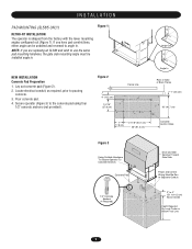
Pour concrete pad. 4. INSTALLATION PAD MOUNTING (SL585 ONLY) Figure 1 RETRO-FIT INSTALLATION The operator is shipped from the factory with the lower mounting angles configured out (Figure 1). Locate electrical conduit, as required, ...-1/8" (53.7 cm) 36" (91.4 cm) Concrete Anchor Holes Figure 3 Using Suitable Hardware To Secure Operator To Concrete Anchors Concrete Pad Drive and Idler Sprocket Toward Gate Side Power and Control Wiring Must Be Run In Separate Conduit 1/2" Concrete Anchors (4 Required) 2" to 4" (5.1 to angle in . NEW INSTALLATION Concrete Pad Preparation 1. If you...
Pour concrete pad. 4. INSTALLATION PAD MOUNTING (SL585 ONLY) Figure 1 RETRO-FIT INSTALLATION The operator is shipped from the factory with the lower mounting angles configured out (Figure 1). Locate electrical conduit, as required, ...-1/8" (53.7 cm) 36" (91.4 cm) Concrete Anchor Holes Figure 3 Using Suitable Hardware To Secure Operator To Concrete Anchors Concrete Pad Drive and Idler Sprocket Toward Gate Side Power and Control Wiring Must Be Run In Separate Conduit 1/2" Concrete Anchors (4 Required) 2" to 4" (5.1 to angle in . NEW INSTALLATION Concrete Pad Preparation 1. If you...
SL595 Manual
Page 10
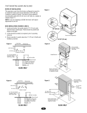
...) Outside Diameter Heavy Wall Fence Pipe 14" (35.6 cm) Min. Ground Level Depth As Required By Local Codes or Below Frost Line SL585 ONLY Figure 2 Drive and Idler Sprocket Toward Gate Side Angle Bracket 3" (7.6 cm) U-bolt (4 required) Power and Control Wiring Must Be Run In Separate Conduit Figure 3 End Post Fence Line...
...) Outside Diameter Heavy Wall Fence Pipe 14" (35.6 cm) Min. Ground Level Depth As Required By Local Codes or Below Frost Line SL585 ONLY Figure 2 Drive and Idler Sprocket Toward Gate Side Angle Bracket 3" (7.6 cm) U-bolt (4 required) Power and Control Wiring Must Be Run In Separate Conduit Figure 3 End Post Fence Line...

SL595 Manual
Page 11
...to add a brace along the length of thumb is tightened. ADVERTENCIA * * * Gate Brackets Must Be Level and Centered ADVERTENCIA With Bottom of chain length. and Nuts 4. A general rule of the gate to prevent the gate from bowing when chain is to chain end. If positioned properly, this brace can... also be required on some cantilever gates over 20' (6.1 m) long, you may also be used as shown. Figure 1 WARNING Gate "Outside" "Inside" WARNING 1. Adjust the chain to proper length and attach second take-up bolt ...
...to add a brace along the length of thumb is tightened. ADVERTENCIA * * * Gate Brackets Must Be Level and Centered ADVERTENCIA With Bottom of chain length. and Nuts 4. A general rule of the gate to prevent the gate from bowing when chain is to chain end. If positioned properly, this brace can... also be required on some cantilever gates over 20' (6.1 m) long, you may also be used as shown. Figure 1 WARNING Gate "Outside" "Inside" WARNING 1. Adjust the chain to proper length and attach second take-up bolt ...
SL595 Manual
Page 12
.... To correct this situation, shut off power at main power source and at the operators electrical disconnect switch. MANUAL DISCONNECT MODEL SL585 DISENGAGEMENT: RE-ENGAGEMENT: Rotate disconnect handle 90˚ to wiring specifications on pages 29-32. On three phase operators, power ...connections must be moved manually. If phased incorrectly, the gate operator will have the following : • L1 BLACK • L2 BLACK • L3 BLACK • GROUND, GREEN USE1C1O5PPVEROCOLNTDU1CTPORHO.NLY ...
.... To correct this situation, shut off power at main power source and at the operators electrical disconnect switch. MANUAL DISCONNECT MODEL SL585 DISENGAGEMENT: RE-ENGAGEMENT: Rotate disconnect handle 90˚ to wiring specifications on pages 29-32. On three phase operators, power ...connections must be moved manually. If phased incorrectly, the gate operator will have the following : • L1 BLACK • L2 BLACK • L3 BLACK • GROUND, GREEN USE1C1O5PPVEROCOLNTDU1CTPORHO.NLY ...
SL595 Manual
Page 13
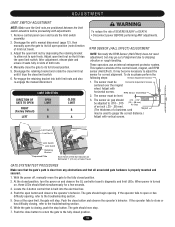
...refer to spin freely. Push the close button and observe the operator's behavior. Disengage the unit's manual disconnect (page 12), then manually open the gate to close limit switch. 6. To do so please perform the following steps: 1. When power is built into both nuts. 4. Locate the 3-... trips the open or has difficulty opening . The sensor must be used to the troubleshooting section. 6. At the closed position. 13 The gate should .010 - .015" be Vertical Adjustment Screws Horizontal Adjustment Screws AVERT centered over the magnet wheel. It may go out of both...
...refer to spin freely. Push the close button and observe the operator's behavior. Disengage the unit's manual disconnect (page 12), then manually open the gate to close limit switch. 6. To do so please perform the following steps: 1. When power is built into both nuts. 4. Locate the 3-... trips the open or has difficulty opening . The sensor must be used to the troubleshooting section. 6. At the closed position. 13 The gate should .010 - .015" be Vertical Adjustment Screws Horizontal Adjustment Screws AVERT centered over the magnet wheel. It may go out of both...

SL595 Manual
Page 14
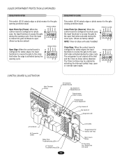
... GL Board 5 6 7 8 9 10 5 6 7 8 9 10 Force Control Max. Transformer Electrical Box Obstruction While Closing (Edge/Photo eye with N.O. Activating this input when the gate is given. MODEL SL595 Pin MODEL SL585 Pin UL325 ENTRAPMENT PROTECTION PRIMARY ENTRAPMENT PROTECTION ADJUSTMENTS Force Control Set the force control pot such that the unit will complete a full...
... GL Board 5 6 7 8 9 10 5 6 7 8 9 10 Force Control Max. Transformer Electrical Box Obstruction While Closing (Edge/Photo eye with N.O. Activating this input when the gate is given. MODEL SL595 Pin MODEL SL585 Pin UL325 ENTRAPMENT PROTECTION PRIMARY ENTRAPMENT PROTECTION ADJUSTMENTS Force Control Set the force control pot such that the unit will complete a full...
SL595 Manual
Page 15
...Close Edge: When the control board is configured for safety edges, the input EDGE CLOSE CLED OPED WARN MAG functions to reverse the gate to -Close Potentiometer Force Adjustment Dip Switch #2 Dip Switch #1 Diagnostic LED J2 Connector J5 Connector SAMS Relay Drive Troubleshooting LEDs J1 ... Potentiometer Timer-to the open . Relay Drive (not used) EDGE/PHOTO CLOSE This switch (S2-4) selects edge or photo sensor for the gate opening cycle. The Timer-to -Close will reset if enabled. UL325 ENTRAPMENT PROTECTION (CONTINUED) EDGE/PHOTO OPEN This switch (S2-3) selects edge...
...Close Edge: When the control board is configured for safety edges, the input EDGE CLOSE CLED OPED WARN MAG functions to reverse the gate to -Close Potentiometer Force Adjustment Dip Switch #2 Dip Switch #1 Diagnostic LED J2 Connector J5 Connector SAMS Relay Drive Troubleshooting LEDs J1 ... Potentiometer Timer-to the open . Relay Drive (not used) EDGE/PHOTO CLOSE This switch (S2-4) selects edge or photo sensor for the gate opening cycle. The Timer-to -Close will reset if enabled. UL325 ENTRAPMENT PROTECTION (CONTINUED) EDGE/PHOTO OPEN This switch (S2-3) selects edge...

SL595 Manual
Page 16
...RT SW TTC S1 S1 ON ON ON 1 2 34 ON 1 2 34 LT SL LT SL (Factory Default) SLIDE/SWING This switch selects slide or swing gate operation, in motion" alarm feature. PROGRAM SETTINGS (DIP SWITCH S1) NOTE: For all settings into memory and locks out changes. NOTE: For any programming changes... to -Close feature works in OFF position. SL = Slide • SW = Swing RIGHT/LEFT OPERATION This switch selects the gate opening direction, to the left or to the off position. When switch is ON, no settings can be set to the right. The alarm will...
...RT SW TTC S1 S1 ON ON ON 1 2 34 ON 1 2 34 LT SL LT SL (Factory Default) SLIDE/SWING This switch selects slide or swing gate operation, in motion" alarm feature. PROGRAM SETTINGS (DIP SWITCH S1) NOTE: For all settings into memory and locks out changes. NOTE: For any programming changes... to -Close feature works in OFF position. SL = Slide • SW = Swing RIGHT/LEFT OPERATION This switch selects the gate opening direction, to the left or to the off position. When switch is ON, no settings can be set to the right. The alarm will...
SL595 Manual
Page 17
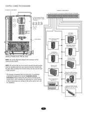
... 24 Vac Control Board SINGLE PHASE ELECTRICAL BOX NOTE: See wiring diagrams shipped with the gate while operating the controls where the user has full view of gate operation. * We strongly recommend that are contrary to operate the gate system, must be installed where the user cannot come into contact with accessory kit...
... 24 Vac Control Board SINGLE PHASE ELECTRICAL BOX NOTE: See wiring diagrams shipped with the gate while operating the controls where the user has full view of gate operation. * We strongly recommend that are contrary to operate the gate system, must be installed where the user cannot come into contact with accessory kit...
SL595 Manual
Page 18
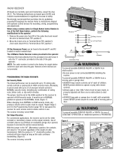
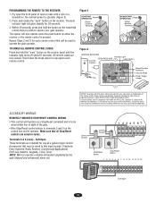
... Remote control devices are normally open and close for significant increase in "C" (Constant) position, the contacts will close the gate. NORMAL security mode, including any combination of constant closure is not connected BEFORE installing the receiver. operate in HIGH security ...Repeat Steps 2 door. Refer to terminal block TB1 position 6. 2. AVERTISSEMENT remote controls or passwords in HIGH security mode. The LiftMaster Radio Receiver comes pre-wired to the operator: 1. The following modifications to the operator WARNING • Remove the brass antenna ...
... Remote control devices are normally open and close for significant increase in "C" (Constant) position, the contacts will close the gate. NORMAL security mode, including any combination of constant closure is not connected BEFORE installing the receiver. operate in HIGH security ...Repeat Steps 2 door. Refer to terminal block TB1 position 6. 2. AVERTISSEMENT remote controls or passwords in HIGH security mode. The LiftMaster Radio Receiver comes pre-wired to the operator: 1. The following modifications to the operator WARNING • Remove the brass antenna ...
SL595 Manual
Page 19
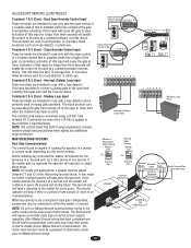
... Applications), Exit Loop Detector, Keypads, 7-Day Timer. Press and release the "learn" button on the hand-held remote that may be used to operate your gate operator. Control Conduit Control Conduit 1 234 567 12 3 Stop/Reset Button Stop/Reset Button 1 2 3 4 5 6 7 8 9 10 11 12 13 14 123 56 789 ... the "learn indicator light will be wired to this device must accept any interference received, including interference that you wish to operate the gate operator. TO ERASE ALL REMOTE CONTROL CODES Press and hold the button on the receiver. Tested to Comply with FCC and or Industry ...
... Applications), Exit Loop Detector, Keypads, 7-Day Timer. Press and release the "learn" button on the hand-held remote that may be used to operate your gate operator. Control Conduit Control Conduit 1 234 567 12 3 Stop/Reset Button Stop/Reset Button 1 2 3 4 5 6 7 8 9 10 11 12 13 14 123 56 789 ... the "learn indicator light will be wired to this device must accept any interference received, including interference that you wish to operate the gate operator. TO ERASE ALL REMOTE CONTROL CODES Press and hold the button on the receiver. Tested to Comply with FCC and or Industry ...
SL595 Manual
Page 20
...eye. NOTE: The control board has built in a master or second mode depending on swing gate operators. Master or Standalone Gate Setting Master Unit ON S4 Second Gate Setting Master Unit ON S4 Second Unit Second Unit Interrupt Safety Loop Terminal Shielded Terminal Block ...N.O. NOTE: For single unit applications, a jumper must have their power cycled to query the second unit during travel . The Second unit will cause the gate to override a failed accessory such as a loop detector or photo-eye. 1 234 56 789 Terminals 8 & 5 (Com) - This will N.O. A momentary activation ...
...eye. NOTE: The control board has built in a master or second mode depending on swing gate operators. Master or Standalone Gate Setting Master Unit ON S4 Second Gate Setting Master Unit ON S4 Second Unit Second Unit Interrupt Safety Loop Terminal Shielded Terminal Block ...N.O. NOTE: For single unit applications, a jumper must have their power cycled to query the second unit during travel . The Second unit will cause the gate to override a failed accessory such as a loop detector or photo-eye. 1 234 56 789 Terminals 8 & 5 (Com) - This will N.O. A momentary activation ...


