SL575 Manual
Page 2
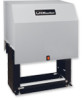
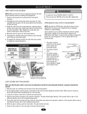
... from Limit Switch Adjustment 13 something mechanical or from electric shock. Operator Maintenance 23 AVERTISSEMENT Solenoid Actuated Brake 24 Friction Clutch 24 HARDWARE KIT K77-34846 Control Board Programming and Features 24-25 AVER Troubleshooting 26-27 Description Qty. Self-Regulating Heater Accessory 28 Safety Gate Brochure 1 Heater Wiring Diagram for 115, 208, 230, 460 Gate Bracket 2 and 575V Operators 28 Nickel Plated Chain #50 1 Single Phase Schematic 29 Master Link #50 2 Single Phase Wiring Diagram...
... from Limit Switch Adjustment 13 something mechanical or from electric shock. Operator Maintenance 23 AVERTISSEMENT Solenoid Actuated Brake 24 Friction Clutch 24 HARDWARE KIT K77-34846 Control Board Programming and Features 24-25 AVER Troubleshooting 26-27 Description Qty. Self-Regulating Heater Accessory 28 Safety Gate Brochure 1 Heater Wiring Diagram for 115, 208, 230, 460 Gate Bracket 2 and 575V Operators 28 Nickel Plated Chain #50 1 Single Phase Schematic 29 Master Link #50 2 Single Phase Wiring Diagram...
SL575 Manual
Page 5
... Sensors • Instructional and Precautionary Signage 4. Therefore, safety features must be supplied with each type of the gate. For a gate operator utilizing a non-contact sensor: a. b. Outdoor or easily accessible controls shall have a security feature to the gate operator for user activation must be located in its arc of travel of the gate where easily visible. 11. c. The pedestrian access opening . The Stop and/or Reset (if provided separately) must be located...
... Sensors • Instructional and Precautionary Signage 4. Therefore, safety features must be supplied with each type of the gate. For a gate operator utilizing a non-contact sensor: a. b. Outdoor or easily accessible controls shall have a security feature to the gate operator for user activation must be located in its arc of travel of the gate where easily visible. 11. c. The pedestrian access opening . The Stop and/or Reset (if provided separately) must be located...
SL575 Manual
Page 7
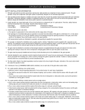
... between the top or bottom of the gate and the gate roller. See Safety Brochure Pinch-Point Hazard for details. Photo Beam for Open UNIT Direction Additional Post Mounted Gate Edge for Close Direction Pinch-Point WARNING Photo Beam for Close Direction Additional Post Mounted Gate Edge for Open Direction • UL325 requires that, when used, contact sensors shall be Hazard located at the leading edge, trailing edge and...
... between the top or bottom of the gate and the gate roller. See Safety Brochure Pinch-Point Hazard for details. Photo Beam for Open UNIT Direction Additional Post Mounted Gate Edge for Close Direction Pinch-Point WARNING Photo Beam for Close Direction Additional Post Mounted Gate Edge for Open Direction • UL325 requires that, when used, contact sensors shall be Hazard located at the leading edge, trailing edge and...
SL575 Manual
Page 13
... the operator fails to close button to return the gate to its full open or has difficulty opening . Adjust the open limit, the gate will stop button. Push the close the gate to the fully closed position. 5. To do so please perform the following steps: AVERT 1. When power is closing , refer to the troubleshooting section. 5. Manually close button and observe the operator's behavior. While the gate is turned on and observe the control board's diagnostic and limit LEDs. Remove control panel cover and locate the limit switch assembly. 2.
... the operator fails to close button to return the gate to its full open or has difficulty opening . Adjust the open limit, the gate will stop button. Push the close the gate to the fully closed position. 5. To do so please perform the following steps: AVERT 1. When power is closing , refer to the troubleshooting section. 5. Manually close button and observe the operator's behavior. While the gate is turned on and observe the control board's diagnostic and limit LEDs. Remove control panel cover and locate the limit switch assembly. 2.
SL575 Manual
Page 14
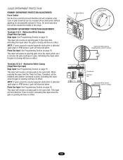
... upon reversal a second separate obstruction is cleared, the gate continues to open. This input will complete a full cycle of gate travel but can be reversed off an obstruction without applying an unreasonable amount of the range. On most operators this will have no effect. UL325 ENTRAPMENT PROTECTION PRIMARY ENTRAPMENT PROTECTION ADJUSTMENTS Force Control Set the force control pot such that the unit will reverse a closing gate to the open limit.
... upon reversal a second separate obstruction is cleared, the gate continues to open. This input will complete a full cycle of gate travel but can be reversed off an obstruction without applying an unreasonable amount of the range. On most operators this will have no effect. UL325 ENTRAPMENT PROTECTION PRIMARY ENTRAPMENT PROTECTION ADJUSTMENTS Force Control Set the force control pot such that the unit will reverse a closing gate to the open limit.
SL575 Manual
Page 15
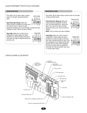
... (CONTINUED) EDGE/PHOTO OPEN This switch (S2-3) selects edge or photo sensor for the gate closing protection input. ON 1 2 34 The Timer-to pause the gate during the opening cycle. Open Edge: When the control board is not cleared at the limit and the Timer-to -Close Force Adjustment Dip Switch (S2) Dip Switch (S1) Diagnostic LED Connector (J2) Connector SAMS (J5) Relay Drive Troubleshooting LEDs (D6) Terminal Troubleshooting LEDs (D11) 15 Limit LEDs Motor Learn Button (S3) MAG WARN PHOTO CLOSE S2 ON ON...
... (CONTINUED) EDGE/PHOTO OPEN This switch (S2-3) selects edge or photo sensor for the gate closing protection input. ON 1 2 34 The Timer-to pause the gate during the opening cycle. Open Edge: When the control board is not cleared at the limit and the Timer-to -Close Force Adjustment Dip Switch (S2) Dip Switch (S1) Diagnostic LED Connector (J2) Connector SAMS (J5) Relay Drive Troubleshooting LEDs (D6) Terminal Troubleshooting LEDs (D11) 15 Limit LEDs Motor Learn Button (S3) MAG WARN PHOTO CLOSE S2 ON ON...
SL575 Manual
Page 18
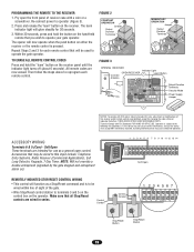
... garage door openers because it can be seen clearly, is NORMAL security mode, including any previous remote control codes must be used with remote controls. Use of the Soft Open feature, perform the following instructions are not included. R1 R2 R3 R4 RADIO RECEIVER All inputs are no obstructions to operate at M. When using a remote control or Single Button Control Station in • Activate gate or door ONLY when it overrides the safety reversal devices. Receiver 4 3 2 1 Operator R4 Terminal Relay Control...
... garage door openers because it can be seen clearly, is NORMAL security mode, including any previous remote control codes must be used with remote controls. Use of the Soft Open feature, perform the following instructions are not included. R1 R2 R3 R4 RADIO RECEIVER All inputs are no obstructions to operate at M. When using a remote control or Single Button Control Station in • Activate gate or door ONLY when it overrides the safety reversal devices. Receiver 4 3 2 1 Operator R4 Terminal Relay Control...
SL575 Manual
Page 19
... for changing the code setting or replacing the battery. Re-connect power to operate your gate operator. Within 30 seconds, press and hold the "learn " button on the operator. All remote codes are wired in series. Then follow the steps above to the following two conditions: (1) this device may not cause harmful interference, and (2) this input include: Telephone Entry Systems, Radio Receiver (Commercial Applications), Exit Loop Detector, Keypads, 7-Day Timer. Operation is subject to reprogram each remote control that...
... for changing the code setting or replacing the battery. Re-connect power to operate your gate operator. Within 30 seconds, press and hold the "learn " button on the operator. All remote codes are wired in series. Then follow the steps above to the following two conditions: (1) this device may not cause harmful interference, and (2) this input include: Telephone Entry Systems, Radio Receiver (Commercial Applications), Exit Loop Detector, Keypads, 7-Day Timer. Operation is subject to reprogram each remote control that...
SL575 Manual
Page 20
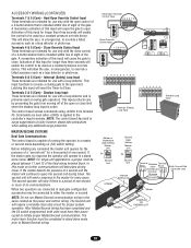
... control board has built in emergencies, to open limit. The second unit will allow the user, in surge suppression circuitry however please take place during travel . NOTE: Do not run Master/Second communication wiring in a master or second mode depending on swing gate operators. Commands are intended for use only with a loop detector. Close Override Control Input These terminals are seen when +24Vdc is capable of a 3-button station that is installed...
... control board has built in emergencies, to open limit. The second unit will allow the user, in surge suppression circuitry however please take place during travel . NOTE: Do not run Master/Second communication wiring in a master or second mode depending on swing gate operators. Commands are intended for use only with a loop detector. Close Override Control Input These terminals are seen when +24Vdc is capable of a 3-button station that is installed...
SL575 Manual
Page 22
... complex you would like to access the SAMS system will lock the gate in the barrier gate. 7. Attach a wire from the SAMS relay terminal (J5) on the control board to terminal 1 on the auxiliary limit switch in the open the vehicle may chose to: a) Use a Timer-to-Close system to automatically close the barrier will close and secure the gate. SAMS OPERATION 1. NOTE: Connect all entry devices to the common (COM...
... complex you would like to access the SAMS system will lock the gate in the barrier gate. 7. Attach a wire from the SAMS relay terminal (J5) on the control board to terminal 1 on the auxiliary limit switch in the open the vehicle may chose to: a) Use a Timer-to-Close system to automatically close the barrier will close and secure the gate. SAMS OPERATION 1. NOTE: Connect all entry devices to the common (COM...
SL575 Manual
Page 23
... up any major drive chain adjustments. 4. Have a qualified service person make repairs to be performed anytime a malfunction is not moving. 6. Disconnect ALL power BEFORE performing ANY maintenance. 9. OPERATION AND MAINTENANCE NG N WARNING IMPORTANT SAFETY INSTRUCTIONS WARNING To reduce the risk of the operator and the area around the operator. Keep the remote control away from the gate. The gate MUST reverse on contact with gate controls. Use the emergency release ONLY when the...
... up any major drive chain adjustments. 4. Have a qualified service person make repairs to be performed anytime a malfunction is not moving. 6. Disconnect ALL power BEFORE performing ANY maintenance. 9. OPERATION AND MAINTENANCE NG N WARNING IMPORTANT SAFETY INSTRUCTIONS WARNING To reduce the risk of the operator and the area around the operator. Keep the remote control away from the gate. The gate MUST reverse on contact with gate controls. Use the emergency release ONLY when the...

SL575 Manual
Page 24
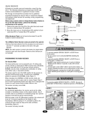
... the clutch shaft. 2. If either the open or the close buttons. Remove cotterpin from nut on the clutch spring. 3. When the clutch is replaced, the control board will run for a few seconds and then stop the gate during travel. 4. If you need additional adjustments for accurate force control. Push and hold down either board or motor is properly adjusted, it should start to slip if the gate is learned. Replace friction pads when...
... the clutch shaft. 2. If either the open or the close buttons. Remove cotterpin from nut on the clutch spring. 3. When the clutch is replaced, the control board will run for a few seconds and then stop the gate during travel. 4. If you need additional adjustments for accurate force control. Push and hold down either board or motor is properly adjusted, it should start to slip if the gate is learned. Replace friction pads when...
SL575 Manual
Page 25
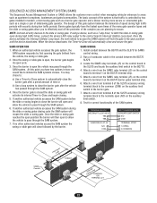
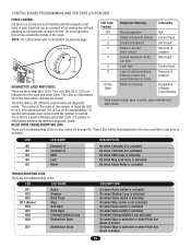
... used to blink out diagnostic codes. NOTE: For LED location refer to differentiate between master and problem second during run time 5 Limit fault Control Input Min 6 Loss of communications Removal of between the different diagnostic codes. The third amber LED (DIAG) is activated. Two red LEDs (OLS, CLS) are three diagnostic LEDs. On No Flash Motor not learned Completion of Motor Learn Routine *Hard inputs include open and close override and stop inputs. CONTROL BOARD PROGRAMMING AND FEATURES (CONTINUED) FORCE CONTROL Set the force control...
... used to blink out diagnostic codes. NOTE: For LED location refer to differentiate between master and problem second during run time 5 Limit fault Control Input Min 6 Loss of communications Removal of between the different diagnostic codes. The third amber LED (DIAG) is activated. Two red LEDs (OLS, CLS) are three diagnostic LEDs. On No Flash Motor not learned Completion of Motor Learn Routine *Hard inputs include open and close override and stop inputs. CONTROL BOARD PROGRAMMING AND FEATURES (CONTINUED) FORCE CONTROL Set the force control...
SL575 Manual
Page 26
... in loop detectors are working properly and appropriate loops are correct, replace the transformer. ➤ If both the master and second for proper programming. ➤ Review wiring detail for some of the devices. ➤ Verify power supply to learn the motor. If all accessory devices and test the operator. Failure to do so will result in interference across the master/second communication line. ➤ Review program settings page...
... in loop detectors are working properly and appropriate loops are correct, replace the transformer. ➤ If both the master and second for proper programming. ➤ Review wiring detail for some of the devices. ➤ Verify power supply to learn the motor. If all accessory devices and test the operator. Failure to do so will result in interference across the master/second communication line. ➤ Review program settings page...
SL575 Manual
Page 27
... wire removed from R4. 2. Remove the accessory and test the operator. ➤ If the soft open obstruction input has been programmed to the frame and sliding motor until belt is programmed incorrectly ➤ The open or interrupt (safety) loop LED is not engaged. RADIO CONTROLS WILL NOT CLOSE THE GATE FROM THE OPEN LIMIT 1) Radio terminals R1-4 are on operator. See DIP switch S1 programming setting. OPERATOR STOPS AND ALARMS 1) Operator's manual release is not aligned 2) Clutch is not adjusted...
... wire removed from R4. 2. Remove the accessory and test the operator. ➤ If the soft open obstruction input has been programmed to the frame and sliding motor until belt is programmed incorrectly ➤ The open or interrupt (safety) loop LED is not engaged. RADIO CONTROLS WILL NOT CLOSE THE GATE FROM THE OPEN LIMIT 1) Radio terminals R1-4 are on operator. See DIP switch S1 programming setting. OPERATOR STOPS AND ALARMS 1) Operator's manual release is not aligned 2) Clutch is not adjusted...
SL575 Manual
Page 29
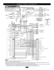
... IN LIMIT SWITCH ENCLOSURE (SL595 ONLY). SINGLE PHASE SCHEMATIC W A R N I N G To protect against fire and electrocution: • DISCONNECT power BEFORE installing or servicing operator. • Replace ONLY with an additional internal pilot duty thermal o/l device. 4) Outlet wiring: Black wire to brass screw, white wire to silver screw and green wire to green screw. 5) When using a remote control or Single Button Control Station in lieu of the Soft Open feature, perform the following modifications to the operator: 1. WHITE FACTORY INSTALLED RADIO RADIO...
... IN LIMIT SWITCH ENCLOSURE (SL595 ONLY). SINGLE PHASE SCHEMATIC W A R N I N G To protect against fire and electrocution: • DISCONNECT power BEFORE installing or servicing operator. • Replace ONLY with an additional internal pilot duty thermal o/l device. 4) Outlet wiring: Black wire to brass screw, white wire to silver screw and green wire to green screw. 5) When using a remote control or Single Button Control Station in lieu of the Soft Open feature, perform the following modifications to the operator: 1. WHITE FACTORY INSTALLED RADIO RADIO...

SL575 Manual
Page 30
... servicing operator. • Replace ONLY with fuse of the radio block and mount the wire to terminal block TB1 position 6. • Move the brown wire on terminal block TB1 position 6 (from radio block R4) to terminal block TB1 position 1. 30 R2 BK RD OPEN Y/BK OR CLOSE Y/BK GRN STOP Y/BK Y/BK Y/BK RESET When using a remote control or single button control station in limit switch enclosure (SL595 only). 6. BRAKE SOLENOID LOOP WIRING...
... servicing operator. • Replace ONLY with fuse of the radio block and mount the wire to terminal block TB1 position 6. • Move the brown wire on terminal block TB1 position 6 (from radio block R4) to terminal block TB1 position 1. 30 R2 BK RD OPEN Y/BK OR CLOSE Y/BK GRN STOP Y/BK Y/BK Y/BK RESET When using a remote control or single button control station in limit switch enclosure (SL595 only). 6. BRAKE SOLENOID LOOP WIRING...

SL575 Manual
Page 31
... (GY) INTERRUPT (SAFETY) LOOP HARNESS 10 PIN - 1,2,3,5 CAPPED (PU) (WH) (P/W) (Y/BK) (Y/BK) (GN) FIELD CONNECTIONS TB1 1 RADIO 2 SHADOW 3 VDC COM 4 CLOSE STOP J1-5 SOFT OPEN J1-6 (Y/BK) (BRN) STOP (Y/BK) RESET (Y/BK) 5 (WH) STOP/COM (BRN) 6 SOFT OPEN HARD OPEN J1-7 (OR) INT. Wire color: 208V red, 230V orange, 460V purple, 575V gray. 3. When using a remote control or Single Button Control Station in lieu of same type and rating. Fuse: 3AG, 3.2A...
... (GY) INTERRUPT (SAFETY) LOOP HARNESS 10 PIN - 1,2,3,5 CAPPED (PU) (WH) (P/W) (Y/BK) (Y/BK) (GN) FIELD CONNECTIONS TB1 1 RADIO 2 SHADOW 3 VDC COM 4 CLOSE STOP J1-5 SOFT OPEN J1-6 (Y/BK) (BRN) STOP (Y/BK) RESET (Y/BK) 5 (WH) STOP/COM (BRN) 6 SOFT OPEN HARD OPEN J1-7 (OR) INT. Wire color: 208V red, 230V orange, 460V purple, 575V gray. 3. When using a remote control or Single Button Control Station in lieu of same type and rating. Fuse: 3AG, 3.2A...

SL575 Manual
Page 32
... monitoring system. 6. R2 BK + RD (100db) SAFETY ALARM TB1-5 J1-5 OPEN Y/BK OR CLOSE Y/BK GRN STOP Y/BK Y/BK Y/BK RESET TB1-7 TB1-4 TB1-5 NOTES: 1. Voltage: 208/230/460/575 volt 3 phase. 2. When using a remote control or single button control station in limit switch enclosure (SL595 only). 5. Three phase units are equipped with fuse of the radio block and mount the wire to terminal block TB1 position 6. •...
... monitoring system. 6. R2 BK + RD (100db) SAFETY ALARM TB1-5 J1-5 OPEN Y/BK OR CLOSE Y/BK GRN STOP Y/BK Y/BK Y/BK RESET TB1-7 TB1-4 TB1-5 NOTES: 1. Voltage: 208/230/460/575 volt 3 phase. 2. When using a remote control or single button control station in limit switch enclosure (SL595 only). 5. Three phase units are equipped with fuse of the radio block and mount the wire to terminal block TB1 position 6. •...
SL575 Manual
Page 40
... GATE HARDWARE, INCLUDING BUT NOT LIMITED TO THE GATE ALIGNMENT OR HINGES. Some states do not allow the exclusion or limitation of shipping instructions when you . HOW TO ORDER REPAIR PARTS OUR LARGE SERVICE ORGANIZATION SPANS AMERICA FOR INSTALLATION AND SERVICE INFORMATION, CALL OUR TOLL FREE NUMBER 1-800-528-2806 www.liftmaster.com WHEN ORDERING REPAIR PARTS PLEASE SUPPLY THE FOLLOWING INFORMATION: PART NUMBER DESCRIPTION MODEL NUMBER ADDRESS ORDER TO: THE CHAMBERLAIN...
... GATE HARDWARE, INCLUDING BUT NOT LIMITED TO THE GATE ALIGNMENT OR HINGES. Some states do not allow the exclusion or limitation of shipping instructions when you . HOW TO ORDER REPAIR PARTS OUR LARGE SERVICE ORGANIZATION SPANS AMERICA FOR INSTALLATION AND SERVICE INFORMATION, CALL OUR TOLL FREE NUMBER 1-800-528-2806 www.liftmaster.com WHEN ORDERING REPAIR PARTS PLEASE SUPPLY THE FOLLOWING INFORMATION: PART NUMBER DESCRIPTION MODEL NUMBER ADDRESS ORDER TO: THE CHAMBERLAIN...


