
GSD Manual
Page 1
SLIDE DOOR OPERATOR MODELS SD & GSD ADDENDUM 2 YEAR W A R R A N T Y Serial # (located on electrical box cover) Installation Date Wiring Type NOT FOR RESIDENTIAL USE 41B6 LISTED DOOR OPERATOR
SLIDE DOOR OPERATOR MODELS SD & GSD ADDENDUM 2 YEAR W A R R A N T Y Serial # (located on electrical box cover) Installation Date Wiring Type NOT FOR RESIDENTIAL USE 41B6 LISTED DOOR OPERATOR

GSD Manual
Page 2
12.02" SPECIFICATIONS 4" Adjustable clearance for door movement between wall and operator. 7.5" Max. 6.0" Min. 13.00" Door Travel plus 4' - 3" 18" Min. 17.13" 17.46" FIGURE 1 Model GSD Single Slide Door Layout Manual Release *Fusible Link Cylindrical Weight 13.08" 4" Adjustable clearance for door movement between wall and operator. 7.5" Max. 6.0" Min. 13.00" Door Travel plus 4' - 3" 24.00" 24.00" 10.50" 20.53" Eye Bolt FIGURE 2 Model SD Bi-Part Slide Door Layout "S" Hook *Fusible link "S" Hook Cylindical Weight 2
12.02" SPECIFICATIONS 4" Adjustable clearance for door movement between wall and operator. 7.5" Max. 6.0" Min. 13.00" Door Travel plus 4' - 3" 18" Min. 17.13" 17.46" FIGURE 1 Model GSD Single Slide Door Layout Manual Release *Fusible Link Cylindrical Weight 13.08" 4" Adjustable clearance for door movement between wall and operator. 7.5" Max. 6.0" Min. 13.00" Door Travel plus 4' - 3" 24.00" 24.00" 10.50" 20.53" Eye Bolt FIGURE 2 Model SD Bi-Part Slide Door Layout "S" Hook *Fusible link "S" Hook Cylindical Weight 2

GSD Manual
Page 3
...addition, disconnect and remove all locking devices from the door to prevent damage or personal injury due to assure this before beginning operator installation. HARDWARE KITS KIT PART # *K77-10473 *K77-10474 K75-10470 K75-10471 K75-10469 K75-16339 DESCRIPTION Complete Hardware... brackets 4 4 4 4 5 6 4 5 6 6 * (4) wall brackets are included in the standard hardware kit. For complete list of the operator. 3. Damage claims must be properly aligned and working smoothly. Make any necessary corrections to the door to accidental locking. Single doors over 14' or Bi...
...addition, disconnect and remove all locking devices from the door to prevent damage or personal injury due to assure this before beginning operator installation. HARDWARE KITS KIT PART # *K77-10473 *K77-10474 K75-10470 K75-10471 K75-10469 K75-16339 DESCRIPTION Complete Hardware... brackets 4 4 4 4 5 6 4 5 6 6 * (4) wall brackets are included in the standard hardware kit. For complete list of the operator. 3. Damage claims must be properly aligned and working smoothly. Make any necessary corrections to the door to accidental locking. Single doors over 14' or Bi...
GSD Manual
Page 4
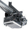
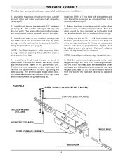
... bolt will have to the front idler. 4. Bolt the angle mounting brackets to each other and install end idler shaft assembly (see page 5). 5. OPERATOR ASSEMBLY The slide door operator should be mounted on the right hand end of the track with the pulleys facing out. Layout the two pieces of the carriage...
... bolt will have to the front idler. 4. Bolt the angle mounting brackets to each other and install end idler shaft assembly (see page 5). 5. OPERATOR ASSEMBLY The slide door operator should be mounted on the right hand end of the track with the pulleys facing out. Layout the two pieces of the carriage...

GSD Manual
Page 6
... heavy doors. 5. It may be used (not provided) between the wall and one sway brace be used . 4. TOP OF DOOR 6 Set the assembled operator into the center-line of throughbolts, lag bolts and shields may be less than 1-1/2" below the slider carriage (see figure 1). SLIDER CARRIAGE 1-1/2" MIN. This... 6). Check that at least one of the bracket is no more than 4 inches, it may be necessary to align the disconnect pin. OPERATOR MOUNTING NOTE: Refer the figures on page 2 for general information during this line on the wall above the door. IMPORTANT: BE SURE...
... heavy doors. 5. It may be used (not provided) between the wall and one sway brace be used . 4. TOP OF DOOR 6 Set the assembled operator into the center-line of throughbolts, lag bolts and shields may be less than 1-1/2" below the slider carriage (see figure 1). SLIDER CARRIAGE 1-1/2" MIN. This... 6). Check that at least one of the bracket is no more than 4 inches, it may be necessary to align the disconnect pin. OPERATOR MOUNTING NOTE: Refer the figures on page 2 for general information during this line on the wall above the door. IMPORTANT: BE SURE...

GSD Manual
Page 7
...top shaft collar up through the hole. 9. Refer to 12 inches below and aligned with the hardware provided (see figure 5). 7. MANUAL OPERATION: The door cannot be manually opened or closed. 7 NOTE: For bi-parting doors, it is disconnected and moves freely. Verify that keyhole... top of door) so that the chain cannot move through the eyelet in the slot of the disconnect pin. 5. ELECTRICAL CONNECTIONS & OPERATING INSTRUCTIONS POWER AND CONTROL WIRING: Refer to the slider with disconnect chain. Mount the chain retaining bracket (with keyhole slot) at a convenient...
...top shaft collar up through the hole. 9. Refer to 12 inches below and aligned with the hardware provided (see figure 5). 7. MANUAL OPERATION: The door cannot be manually opened or closed. 7 NOTE: For bi-parting doors, it is disconnected and moves freely. Verify that keyhole... top of door) so that the chain cannot move through the eyelet in the slot of the disconnect pin. 5. ELECTRICAL CONNECTIONS & OPERATING INSTRUCTIONS POWER AND CONTROL WIRING: Refer to the slider with disconnect chain. Mount the chain retaining bracket (with keyhole slot) at a convenient...


