LM21XPBB Manual
Page 1
The Chamberlain Group, Inc. 845 Larch Avenue Elmhurst, Illinois 60126-1196 www.liftmaster.com OWNER'S MANUAL MODELS LM21XPBB LM21XPBBVB EXTENDED PERFORMANCE RELEASE DEVICE APPROVED
The Chamberlain Group, Inc. 845 Larch Avenue Elmhurst, Illinois 60126-1196 www.liftmaster.com OWNER'S MANUAL MODELS LM21XPBB LM21XPBBVB EXTENDED PERFORMANCE RELEASE DEVICE APPROVED
LM21XPBB Manual
Page 2
... sounder, and diagnostic feedback LEDs. Read them . INTRODUCTION GENERAL DESCRIPTION The LiftMaster® LM21XPBB and LM21XPBBVB Release Device is UL/ULC listed normally energized fail-safe device designed for the ADVERTENCIA release device and accessories. All models are used with a fusible link system. PRECAUCIÓN The release device can be activated via a smoke detector or an alarm relay from...
... sounder, and diagnostic feedback LEDs. Read them . INTRODUCTION GENERAL DESCRIPTION The LiftMaster® LM21XPBB and LM21XPBBVB Release Device is UL/ULC listed normally energized fail-safe device designed for the ADVERTENCIA release device and accessories. All models are used with a fusible link system. PRECAUCIÓN The release device can be activated via a smoke detector or an alarm relay from...
LM21XPBB Manual
Page 3
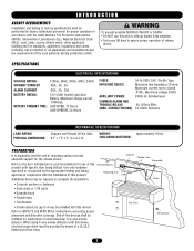
...COMMON ALARM ANAD TTENTION TROUBLE RELAYS: .5A 125Vac 60Hz (MAX. Refer to assure proper operation of release device. AVERMTaxiImSumScEurrMent EnotNtoTexceed .010A.; End-of-line devices shall be installed for supervision of electrical power to NFPA 72 and NFPA 80 for use of ..., .25A 12V 4.5AH Sealed Lead Acid Battery, Maximum charge current .150Amps LM21XPBB, 72 Hours LM21XPBBVB, 24 Hours FUSES: 3A @ 250V, 2AG Slo-Blo Type INITIATING DEVICE: Maximum line impedance 20 ohm; Releasing Unit Additional items may be required to complete the installation: • Concrete anchors...
...COMMON ALARM ANAD TTENTION TROUBLE RELAYS: .5A 125Vac 60Hz (MAX. Refer to assure proper operation of release device. AVERMTaxiImSumScEurrMent EnotNtoTexceed .010A.; End-of-line devices shall be installed for supervision of electrical power to NFPA 72 and NFPA 80 for use of ..., .25A 12V 4.5AH Sealed Lead Acid Battery, Maximum charge current .150Amps LM21XPBB, 72 Hours LM21XPBBVB, 24 Hours FUSES: 3A @ 250V, 2AG Slo-Blo Type INITIATING DEVICE: Maximum line impedance 20 ohm; Releasing Unit Additional items may be required to complete the installation: • Concrete anchors...
LM21XPBB Manual
Page 4
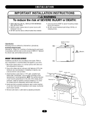
...Install an eyebolt a minimum distance of 40 lbs. Fusible Links Turnbuckle Chain Fire Door Annunciator 4 End Link MOUNT THE RELEASE DEVICE Installation procedures vary according to door Smoke Detector TENCIA ADVERTENCIA manufacturer's recommendations. Install hardware (sash chain or 1/16" cable...not provided). DO NOT exceed maximum pull rating of 12" from Link the release device to allow insertion of the release device Releasing Unit Chain End enclosure. Secure the release device enclosure with the most current version of enclosure. 2. Remove sash chain or cable...
...Install an eyebolt a minimum distance of 40 lbs. Fusible Links Turnbuckle Chain Fire Door Annunciator 4 End Link MOUNT THE RELEASE DEVICE Installation procedures vary according to door Smoke Detector TENCIA ADVERTENCIA manufacturer's recommendations. Install hardware (sash chain or 1/16" cable...not provided). DO NOT exceed maximum pull rating of 12" from Link the release device to allow insertion of the release device Releasing Unit Chain End enclosure. Secure the release device enclosure with the most current version of enclosure. 2. Remove sash chain or cable...
LM21XPBB Manual
Page 5
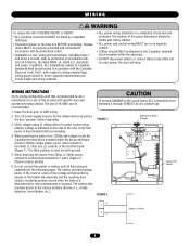
... • ALL electrical connections MUST be made by AVERTISSEMENT door CAUTION manufacturer for the release device as well as the door operator, before proceeding. 4. When powering the device from 24Vac or 24Vdc power, connect to power capacity requirements and circuit length and wiring... methods. The location of the fusible link assembly and the resulting door closure. Verify voltage rating of release device to the circuit board, ALL connections from 120Vac line voltage, locate the 3-position terminal block mounted within the enclosure. CI&#...
... • ALL electrical connections MUST be made by AVERTISSEMENT door CAUTION manufacturer for the release device as well as the door operator, before proceeding. 4. When powering the device from 24Vac or 24Vdc power, connect to power capacity requirements and circuit length and wiring... methods. The location of the fusible link assembly and the resulting door closure. Verify voltage rating of release device to the circuit board, ALL connections from 120Vac line voltage, locate the 3-position terminal block mounted within the enclosure. CI&#...
LM21XPBB Manual
Page 8
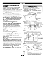
.... Observe proper polarity, 3 (+), 4 (-) when attaching to the release device's terminal board. This option is shown. (+) Power from N/O 4-Wire initiating device loop to 4-wire smoke detector. • DO NOT install this device, the smoke detectors must be powered from a source other N/O 4-... damage to positions 3 and 4. Observe proper polarity, 3 (+), 4 (-) when attaching to the release device's terminal board. This option is placed between devices may be installed with this device, electrical supervision must be provided by means of a UL/ULC listed end-of-line relay. This...
.... Observe proper polarity, 3 (+), 4 (-) when attaching to the release device's terminal board. This option is shown. (+) Power from N/O 4-Wire initiating device loop to 4-wire smoke detector. • DO NOT install this device, the smoke detectors must be powered from a source other N/O 4-... damage to positions 3 and 4. Observe proper polarity, 3 (+), 4 (-) when attaching to the release device's terminal board. This option is placed between devices may be installed with this device, electrical supervision must be provided by means of a UL/ULC listed end-of-line relay. This...
LM21XPBB Manual
Page 9
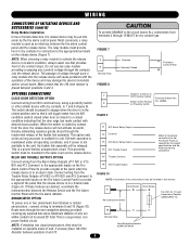
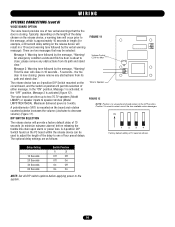
...Resistor between positions 3 and 4. 5 6 Terminal Strip FIGURE 8 Common Normally Closed - FIGURE 7 NOTE: When choosing a relay module to activate the release device in an alarm condition, always select one or two (maximum) horn/strobes or similar annunciators , connect wiring to unit. Fire Alarm Control Panel + ... OPTION Connect wiring from its N/O condition (switch closed when door is closed) to engage when the door is used as the release device. LM56A 11 N/C Alarm Relay Output 12 Common 13 N/O Alarm Relay Output 14 N/C Trouble Output Make all operating conditions, and ...
...Resistor between positions 3 and 4. 5 6 Terminal Strip FIGURE 8 Common Normally Closed - FIGURE 7 NOTE: When choosing a relay module to activate the release device in an alarm condition, always select one or two (maximum) horn/strobes or similar annunciators , connect wiring to unit. Fire Alarm Control Panel + ... OPTION Connect wiring from its N/O condition (switch closed when door is closed) to engage when the door is used as the release device. LM56A 11 N/C Alarm Relay Output 12 Common 13 N/O Alarm Relay Output 14 N/C Trouble Output Make all operating conditions, and ...
LM21XPBB Manual
Page 10
...: Message 1: Warning tone followed by the message, "Warning! please remove any obstructions from its path and stand clear." The release device has an 4-position DIP Switch mounted on the board and rotation counterclockwise increases the volume (clockwise to decrease volume) (Figure 11... A potentiometer (VR1) is 5 watts. ON 1 2 3 4 Factory default setting of the two available voice messages. DIP SWITCH SELECTION The release device will close ; the fire door is now closing . There are as follows: FIGURE 11 Volume Control CCW for example, a 20 second delay...
...: Message 1: Warning tone followed by the message, "Warning! please remove any obstructions from its path and stand clear." The release device has an 4-position DIP Switch mounted on the board and rotation counterclockwise increases the volume (clockwise to decrease volume) (Figure 11... A potentiometer (VR1) is 5 watts. ON 1 2 3 4 Factory default setting of the two available voice messages. DIP SWITCH SELECTION The release device will close ; the fire door is now closing . There are as follows: FIGURE 11 Volume Control CCW for example, a 20 second delay...
LM21XPBB Manual
Page 11
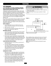
... the door is in order to drop. Raise the door and then reset the release device by pushing downward on side of release device. Press the "Reset" button on the device and release the reset button in fully open position. Testing does not affect normal operation of ... will be accomplished with power applied to unit to the red terminal. 2. After the selected delay expires, the device will prohibit the release device from energizing and releasing the end link. NOTE: Testing shall be interpreted as delay expires. ADVERTENCIA PRECAUCIÓN SUSPENSION OF POWER 1. Reset...
... the door is in order to drop. Raise the door and then reset the release device by pushing downward on side of release device. Press the "Reset" button on the device and release the reset button in fully open position. Testing does not affect normal operation of ... will be accomplished with power applied to unit to the red terminal. 2. After the selected delay expires, the device will prohibit the release device from energizing and releasing the end link. NOTE: Testing shall be interpreted as delay expires. ADVERTENCIA PRECAUCIÓN SUSPENSION OF POWER 1. Reset...
LM21XPBB Manual
Page 12
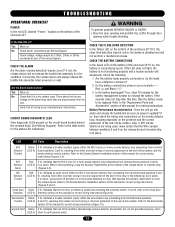
...on the alarm lines when they are disconnected from either incorrect wiring or incorrect placement of the end-of the release device to reset the release device. If the LED does not light, the battery is applied? When lit during testing, press the Auxiliary ...enclosure lit? If so, the battery is in alarm. If not, the release device will not perform a mechanical release. TROUBLESHOOTING OPERATIONAL CHECKLIST POWER Is the red LED, labeled "Power," located on the release device's terminal strip is connected properly. Is the Red LED Lit? voltage should...
...on the alarm lines when they are disconnected from either incorrect wiring or incorrect placement of the end-of the release device to reset the release device. If the LED does not light, the battery is applied? When lit during testing, press the Auxiliary ...enclosure lit? If so, the battery is in alarm. If not, the release device will not perform a mechanical release. TROUBLESHOOTING OPERATIONAL CHECKLIST POWER Is the red LED, labeled "Power," located on the release device's terminal strip is connected properly. Is the Red LED Lit? voltage should...
LM21XPBB Manual
Page 13
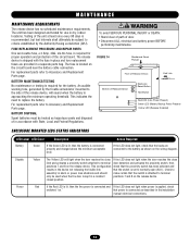
... is set to criteria established by the trouble annunciator mounted to replace the battery. WARNING MAINTENANCE WARNING MAINCTENAAUNCTE IROEQNUIREMENTS The release device has no scheduled maintenance requirements. This configuration check that the switch is recommended, but test intervals shall ultimately be treated... lit, then the line power is connected and If the LED does not light when power is located on the release device. An audible ATTENTION warning tone, generated by the Authority Having Jurisdiction (AHJ). ADVERTENCIA ADVERTENCIA Disable Yellow The Yellow LED...
... is set to criteria established by the trouble annunciator mounted to replace the battery. WARNING MAINTENANCE WARNING MAINCTENAAUNCTE IROEQNUIREMENTS The release device has no scheduled maintenance requirements. This configuration check that the switch is recommended, but test intervals shall ultimately be treated... lit, then the line power is connected and If the LED does not light when power is located on the release device. An audible ATTENTION warning tone, generated by the Authority Having Jurisdiction (AHJ). ADVERTENCIA ADVERTENCIA Disable Yellow The Yellow LED...


