LM21XPBB Manual
Page 1
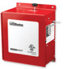
The Chamberlain Group, Inc. 845 Larch Avenue Elmhurst, Illinois 60126-1196 www.liftmaster.com OWNER'S MANUAL MODELS LM21XPBB LM21XPBBVB EXTENDED PERFORMANCE RELEASE DEVICE APPROVED
The Chamberlain Group, Inc. 845 Larch Avenue Elmhurst, Illinois 60126-1196 www.liftmaster.com OWNER'S MANUAL MODELS LM21XPBB LM21XPBBVB EXTENDED PERFORMANCE RELEASE DEVICE APPROVED
LM21XPBB Manual
Page 2
... 3 Specifications 3 WARNING Preparation 3 INSTALLATION Important Installation Warnings 4 CAUTION Mount the Release Device 4 WIRING Wiring Instructions 5 Wire Routing 6 Wiring Diagram 7 Connections of Initiating Devices and Accessories 8-9 Optional Connections 9-10 TESTING Test Procedures 11 TROUBLESHOOTING Operational Checklist 12 MAAVINETERNATNCISE SEMENT Maintenance Requirements 13 ATTENTION Enclosure Mounted LEDs Status Indicators 13 ACCESSORIES AND REPAIR PARTS 14 APPENDIX 15 WARNING Mechanical CAUTION WWEAlAecRRtriNcNaIlINNGG CAWUATRIONNING When you see this manual and...
... 3 Specifications 3 WARNING Preparation 3 INSTALLATION Important Installation Warnings 4 CAUTION Mount the Release Device 4 WIRING Wiring Instructions 5 Wire Routing 6 Wiring Diagram 7 Connections of Initiating Devices and Accessories 8-9 Optional Connections 9-10 TESTING Test Procedures 11 TROUBLESHOOTING Operational Checklist 12 MAAVINETERNATNCISE SEMENT Maintenance Requirements 13 ATTENTION Enclosure Mounted LEDs Status Indicators 13 ACCESSORIES AND REPAIR PARTS 14 APPENDIX 15 WARNING Mechanical CAUTION WWEAlAecRRtriNcNaIlINNGG CAWUATRIONNING When you see this manual and...
LM21XPBB Manual
Page 3
... ohm; Max. 9.7" x 7.5" x 5" (h x w x d) WEIGHT: (INCLUDING BATTERIES) Approximately 18 lbs. CONTACT RATING) 1A 24Vdc Resistive LOAD RATING: PHYSICAL DIMENSIONS: MECHANICAL SPECIFICATIONS Support and Release 40 lbs. When using 4-wire smoke detectors with the installation of the local authority having jurisdiction (AHJ). PREPARATION It is imperative that the wall or mounting surface provide adequate support for use this device without fusible links installed. • Test every 90...
... ohm; Max. 9.7" x 7.5" x 5" (h x w x d) WEIGHT: (INCLUDING BATTERIES) Approximately 18 lbs. CONTACT RATING) 1A 24Vdc Resistive LOAD RATING: PHYSICAL DIMENSIONS: MECHANICAL SPECIFICATIONS Support and Release 40 lbs. When using 4-wire smoke detectors with the installation of the local authority having jurisdiction (AHJ). PREPARATION It is imperative that the wall or mounting surface provide adequate support for use this device without fusible links installed. • Test every 90...
LM21XPBB Manual
Page 4
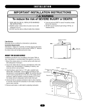
... eyebolt a minimum distance of the release device Releasing Unit Chain End enclosure. Install end link by pressing mechanical reset to allow insertion of 40 lbs. Push end link completely in masonry, use this device without fusible links installed. 4. READ AND FOLLOW ALL INSTALLATION WARNINGS AND INSTRUCTIONS. 2. NEVER connect release device to power source until instructed to door Smoke Detector TENCIA ADVERTENCIA manufacturer's recommendations. DO NOT use concrete anchors (not provided). DO...
... eyebolt a minimum distance of the release device Releasing Unit Chain End enclosure. Install end link by pressing mechanical reset to allow insertion of 40 lbs. Push end link completely in masonry, use this device without fusible links installed. 4. READ AND FOLLOW ALL INSTALLATION WARNINGS AND INSTRUCTIONS. 2. NEVER connect release device to power source until instructed to door Smoke Detector TENCIA ADVERTENCIA manufacturer's recommendations. DO NOT use concrete anchors (not provided). DO...
LM21XPBB Manual
Page 5
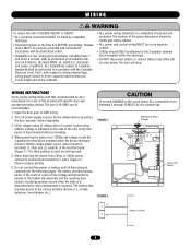
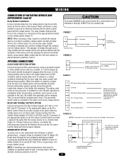
... clearly labeled. • Disconnect power at the fuse box BEFORE proceeding. accordance with that power is used for the release device as well as the door operator, before proceeding. 4. and Class 2 circuits, shall be made by AVERTISSEMENT door CAUTION manufacturer for use of ALL wiring and connections, including Class 1 block mounted within the device enclosure. WARNING ON WIRING INSTRUCTIONS Verify wiring configuration with local electrical codes. • 120Vac should...
... clearly labeled. • Disconnect power at the fuse box BEFORE proceeding. accordance with that power is used for the release device as well as the door operator, before proceeding. 4. and Class 2 circuits, shall be made by AVERTISSEMENT door CAUTION manufacturer for use of ALL wiring and connections, including Class 1 block mounted within the device enclosure. WARNING ON WIRING INSTRUCTIONS Verify wiring configuration with local electrical codes. • 120Vac should...
LM21XPBB Manual
Page 6
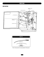
WIRE ROUTING WIRING Low Voltage Wiring High Voltage Wiring Mechanical Reset Plunger Power Strip Ground L1 L2 16 15 14 13 12 11 10 9 8 7 6 5 4 3 2 1 Annunciator Wiring with Sleeve Voice Board Wiring PARTS KIT LMEOLRES-10 Wire Jumper 10k Ohm Resistor Refer to wiring section for proper application of these parts. 6
WIRE ROUTING WIRING Low Voltage Wiring High Voltage Wiring Mechanical Reset Plunger Power Strip Ground L1 L2 16 15 14 13 12 11 10 9 8 7 6 5 4 3 2 1 Annunciator Wiring with Sleeve Voice Board Wiring PARTS KIT LMEOLRES-10 Wire Jumper 10k Ohm Resistor Refer to wiring section for proper application of these parts. 6
LM21XPBB Manual
Page 7
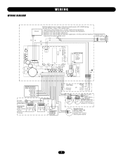
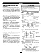
...) 2-Wire Detector Initiation Loop (1) (3) Place 10 kOhm resistor between 5 & 6 if unused. In/Out NC COM Normally Closed Initiation Loop (1) (3) Place wire jumper between 3 & 4 if unused + In + Out - Use only 250Vac, 3 Amp, 3 AG, Slo-Blo fuses. 1. Supervised non-power limited circuit. Speaker BK BK 12 V, 4.5 AHr Battery 2 Amp maximum current RD GR L3 L2 L1 3 Amp, 250 V, 3AG Slo-Blo Auxiliary Common Relay Connections Trouble NO Trouble...
...) 2-Wire Detector Initiation Loop (1) (3) Place 10 kOhm resistor between 5 & 6 if unused. In/Out NC COM Normally Closed Initiation Loop (1) (3) Place wire jumper between 3 & 4 if unused + In + Out - Use only 250Vac, 3 Amp, 3 AG, Slo-Blo fuses. 1. Supervised non-power limited circuit. Speaker BK BK 12 V, 4.5 AHr Battery 2 Amp maximum current RD GR L3 L2 L1 3 Amp, 250 V, 3AG Slo-Blo Auxiliary Common Relay Connections Trouble NO Trouble...
LM21XPBB Manual
Page 8
... approved UL1481 regulated power supply providing battery backup support. (-) Power from Control Panel NOTE: Generic version of a N/C 4-wire smoke detector is shown. (+) Power from Control Panel (-) LMEOLR1224 (+) Alarm Contacts (-) (+) (-) 12/24 Vdc EOL Relay Style A (N/O) 10k Ohm @1/2 watt Terminal Strip Supervisory Resistor (LMEOLRES-10) (+) 3 ADVERTENCIA 4 PRECAUCIÓN (-) IMPORTANT: When using 4-wire smoke detectors with other N/O 4-wire smoke detectors. (-) Power from N/O initiating device loop to positions 3 and 4. OR Relay Module Installation as shown...
... approved UL1481 regulated power supply providing battery backup support. (-) Power from Control Panel NOTE: Generic version of a N/C 4-wire smoke detector is shown. (+) Power from Control Panel (-) LMEOLR1224 (+) Alarm Contacts (-) (+) (-) 12/24 Vdc EOL Relay Style A (N/O) 10k Ohm @1/2 watt Terminal Strip Supervisory Resistor (LMEOLRES-10) (+) 3 ADVERTENCIA 4 PRECAUCIÓN (-) IMPORTANT: When using 4-wire smoke detectors with other N/O 4-wire smoke detectors. (-) Power from N/O initiating device loop to positions 3 and 4. OR Relay Module Installation as shown...
LM21XPBB Manual
Page 9
... Control Panel to unit. The passage of voltage through the contacts into alarm by the project specifications and the Authority Having Jurisdiction ADVERTENCIA 15 Trouble Common Connect wiring from N/O electrical loop, using a proximity switch or other similar device with the fire alarm installer. The switch should be installed on N/O Proximity Switch Attach to 7 and 8 (Figure 8). When the switch is used as power is closed) to a closed condition indicating that the release...
... Control Panel to unit. The passage of voltage through the contacts into alarm by the project specifications and the Authority Having Jurisdiction ADVERTENCIA 15 Trouble Common Connect wiring from N/O electrical loop, using a proximity switch or other similar device with the fire alarm installer. The switch should be installed on N/O Proximity Switch Attach to 7 and 8 (Figure 8). When the switch is used as power is closed) to a closed condition indicating that the release...
LM21XPBB Manual
Page 10
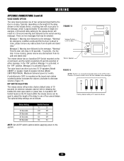
... On On NOTE: Set all DIP switch options before applying power to minimize nuisance alarms) before releasing the fusible link chain upon alarm or power loss. Message 2: Warning tone followed by the message, "Warning! please remove any obstructions from its path and stand clear." There are as follows: FIGURE 11 Volume Control CCW for Max Wire to Speaker FIGURE 12...
... On On NOTE: Set all DIP switch options before applying power to minimize nuisance alarms) before releasing the fusible link chain upon alarm or power loss. Message 2: Warning tone followed by the message, "Warning! please remove any obstructions from its path and stand clear." There are as follows: FIGURE 11 Volume Control CCW for Max Wire to Speaker FIGURE 12...
LM21XPBB Manual
Page 11
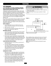
... POWER UP 1. MECHANICAL RELEASE 1. Unit will prohibit the release device from energizing and releasing the end link. Reset the test button (Figure 13). 3. The release device is independent of, and shall in order to reset the alarm loop. 11 Reset the door per door manufacturer's instructions. Press the "Reset" button on the battery. Connect black battery wire to the black terminal on the device to latch end link. Using the chain hoist or motor operator, lower...
... POWER UP 1. MECHANICAL RELEASE 1. Unit will prohibit the release device from energizing and releasing the end link. Reset the test button (Figure 13). 3. The release device is independent of, and shall in order to reset the alarm loop. 11 Reset the door per door manufacturer's instructions. Press the "Reset" button on the battery. Connect black battery wire to the black terminal on the device to latch end link. Using the chain hoist or motor operator, lower...
LM21XPBB Manual
Page 12
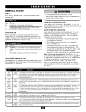
... manual for correct wiring instructions (Figures 3-5). Refer to the "Replacement Parts and Accessories" section of the enclosure lit? Does the unit go into alarm and release the fusible link as soon as part of the wiring diagram. Green If lit, indicates that all wiring is connected properly. Ground Fault Yellow If lit, indicates that the N/O 2-wire (or 4-wire) smoke detector loop (emanating from the unit. TROUBLESHOOTING OPERATIONAL CHECKLIST POWER Is the red LED, labeled "Power," located...
... manual for correct wiring instructions (Figures 3-5). Refer to the "Replacement Parts and Accessories" section of the enclosure lit? Does the unit go into alarm and release the fusible link as soon as part of the wiring diagram. Green If lit, indicates that all wiring is connected properly. Ground Fault Yellow If lit, indicates that the N/O 2-wire (or 4-wire) smoke detector loop (emanating from the unit. TROUBLESHOOTING OPERATIONAL CHECKLIST POWER Is the red LED, labeled "Power," located...
LM21XPBB Manual
Page 13
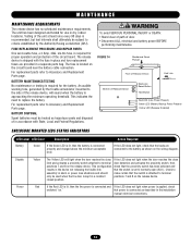
... battery cable connection. FUSE REPLACEMENT PROCEDURE AND REPAIR PARTS One serviceable fuse, a 3 Amp, 3AG, slo-blo fuse, is required for proper operation and protection of Release Device Test Button Red LED (Line Power Present) Green LED (Battery Backup Power Present) Yellow LED (Release Disabled) ENCLOSURE MOUNTED LEDS STATUS INDICATORS LED Label LED Color Description Action Required Battery Green If the Green LED is lit, then the battery is connected If the LED does not light, check that the switch is approaching the minimum operating threshold. TISSEMENT BATTERY MAINTENANCE...
... battery cable connection. FUSE REPLACEMENT PROCEDURE AND REPAIR PARTS One serviceable fuse, a 3 Amp, 3AG, slo-blo fuse, is required for proper operation and protection of Release Device Test Button Red LED (Line Power Present) Green LED (Battery Backup Power Present) Yellow LED (Release Disabled) ENCLOSURE MOUNTED LEDS STATUS INDICATORS LED Label LED Color Description Action Required Battery Green If the Green LED is lit, then the battery is connected If the LED does not light, check that the switch is approaching the minimum operating threshold. TISSEMENT BATTERY MAINTENANCE...
LM21XPBB Manual
Page 14
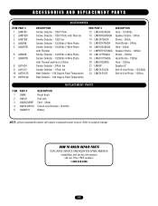
... Speaker 8" End-of-Line Relay - 12/24Vdc End-of-Line Relay - 120Vac REPLACEMENT PARTS ITEM PART # 1 LMRK 2 LMELH 3 LM2AG3AMP 4 LMEOLRES10 5 LM4AH12 DESCRIPTION Reset Knob End Link Fuse - 3Amp End-of-Line Resistor, 10 kOhm Battery NOTE: Certain accessories above will require a separate power source. HOW TO ORDER REPAIR PARTS OUR LARGE SERVICE ORGANIZATION SPANS AMERICA Installation and service information call our TOLL FREE number: 1-800-528-2806 14...
... Speaker 8" End-of-Line Relay - 12/24Vdc End-of-Line Relay - 120Vac REPLACEMENT PARTS ITEM PART # 1 LMRK 2 LMELH 3 LM2AG3AMP 4 LMEOLRES10 5 LM4AH12 DESCRIPTION Reset Knob End Link Fuse - 3Amp End-of-Line Resistor, 10 kOhm Battery NOTE: Certain accessories above will require a separate power source. HOW TO ORDER REPAIR PARTS OUR LARGE SERVICE ORGANIZATION SPANS AMERICA Installation and service information call our TOLL FREE number: 1-800-528-2806 14...
LM21XPBB Manual
Page 15
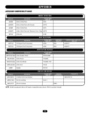
... a separate power source. LMEOLRES-10 LMEOLR120 End-of -Line Relay END-OF-LINE DEVICE SYSTEM SENSOR MODEL NO. Refer to product manual. 15 LIFTMASTER NO. APPENDIX ACCESSORY COMPATIBILITY GUIDE MODEL NO. EOLR-1 SPACE AGE ELECTRONICS NO. LM2WB LM2WTB LM4WB LM4WTB LM1424 SMOKE DETECTORS DESCRIPTION 24Vdc 2-Wire Photo SYSTEM SENSOR MODEL NO. 2W-B 24Vdc 2-Wire Photo with Thermal 2WT-B 24Vdc 4-Wire Photo 4W-B 24Vdc 4-Wire Photo with Thermal & Form C Relay 4WT...
... a separate power source. LMEOLRES-10 LMEOLR120 End-of -Line Relay END-OF-LINE DEVICE SYSTEM SENSOR MODEL NO. Refer to product manual. 15 LIFTMASTER NO. APPENDIX ACCESSORY COMPATIBILITY GUIDE MODEL NO. EOLR-1 SPACE AGE ELECTRONICS NO. LM2WB LM2WTB LM4WB LM4WTB LM1424 SMOKE DETECTORS DESCRIPTION 24Vdc 2-Wire Photo SYSTEM SENSOR MODEL NO. 2W-B 24Vdc 2-Wire Photo with Thermal 2WT-B 24Vdc 4-Wire Photo 4W-B 24Vdc 4-Wire Photo with Thermal & Form C Relay 4WT...

LM21XPBB Manual
Page 16
01-32051D 2/11/08 © 2008, The Chamberlain Group, Inc. All Rights Reserved
01-32051D 2/11/08 © 2008, The Chamberlain Group, Inc. All Rights Reserved


