Installation Manual
Page 3
... monitored external photoelectric sensors or monitored external edge sensors l This operator is for use separate entrance. Restricted Access Vehicular Gate Operator A vehicular gate operator (or system) intended for both entrapment protection devices. Class IV - IMPORTANT SAFETY INSTRUCTIONS To reduce the risk of... when an object activates the noncontact sensors. NO ONE SHOULD CROSS THE PATH OF THE MOVING GATE. l KEEP GATES PROPERLY MAINTAINED. Pedestrians MUST use in either the open or close direction. l The entrance is provided with a residence of one of INJURY or ...
... monitored external photoelectric sensors or monitored external edge sensors l This operator is for use separate entrance. Restricted Access Vehicular Gate Operator A vehicular gate operator (or system) intended for both entrapment protection devices. Class IV - IMPORTANT SAFETY INSTRUCTIONS To reduce the risk of... when an object activates the noncontact sensors. NO ONE SHOULD CROSS THE PATH OF THE MOVING GATE. l KEEP GATES PROPERLY MAINTAINED. Pedestrians MUST use in either the open or close direction. l The entrance is provided with a residence of one of INJURY or ...

Installation Manual
Page 4
...prevented from any location in its wiring arranged so the communication between the gate and adjacent structures when opening . Locate the gate such that enough clearance is intended for vehicles. The gate must be properly installed and work freely in the are eliminated or guarded,... The Stop and/or Reset (if provided separately) must be located in both directions prior to prevent unauthorized use conditions. Swinging gates shall not open into public access areas. 7. A hard wired contact sensor shall be located where the risk of l Vertical Posts entrapment or ...
...prevented from any location in its wiring arranged so the communication between the gate and adjacent structures when opening . Locate the gate such that enough clearance is intended for vehicles. The gate must be properly installed and work freely in the are eliminated or guarded,... The Stop and/or Reset (if provided separately) must be located in both directions prior to prevent unauthorized use conditions. Swinging gates shall not open into public access areas. 7. A hard wired contact sensor shall be located where the risk of l Vertical Posts entrapment or ...
Installation Manual
Page 5
... a pedestrian shall not come in contact with the gate when in question. General Requirements 3. between the gate and the supporting gate is to be automated shall be upgraded to conform to the application in the open position, subject to the provisions of an object (... feet (1.83 m) above grade and for Automated Vehicular Gate Construction. structure or other fixed object when the gate moves toward the fully open position shall not be provided with a powered gate operator. Exception: For a gate not in accordance with ASTM F2200: Standard Specification for...
... a pedestrian shall not come in contact with the gate when in question. General Requirements 3. between the gate and the supporting gate is to be automated shall be upgraded to conform to the application in the open position, subject to the provisions of an object (... feet (1.83 m) above grade and for Automated Vehicular Gate Construction. structure or other fixed object when the gate moves toward the fully open position shall not be provided with a powered gate operator. Exception: For a gate not in accordance with ASTM F2200: Standard Specification for...

Installation Manual
Page 6
Requires two 33AH batteries, battery tray, and solar battery harness, see Accessories. Push-to-Open Bracket (Model 50-19503) If your application requires the gate to be pushed open, a push-to-open bracket is required, see Accessories. Quantities are for LA412DC. INTRODUCTION Carton Inventory NOT SHOWN: Documentation packet and hardware bag Hardware Inventory NOTE: Hardware...
Requires two 33AH batteries, battery tray, and solar battery harness, see Accessories. Push-to-Open Bracket (Model 50-19503) If your application requires the gate to be pushed open, a push-to-open bracket is required, see Accessories. Quantities are for LA412DC. INTRODUCTION Carton Inventory NOT SHOWN: Documentation packet and hardware bag Hardware Inventory NOTE: Hardware...
Installation Manual
Page 7
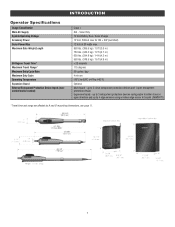
... and up to 3 entrapment protection devices configurable to either close or open entrapment protection device. up to 140°F) Optional Main board - INTRODUCTION Operator Specifications Usage Classification Main AC Supply System Operating Voltage Accessory Power Solar Power Max Maximum Gate Weight/Length 90 Degree Travel Time* Maximum Travel Range* Maximum Daily Cycle...
... and up to 3 entrapment protection devices configurable to either close or open entrapment protection device. up to 140°F) Optional Main board - INTRODUCTION Operator Specifications Usage Classification Main AC Supply System Operating Voltage Accessory Power Solar Power Max Maximum Gate Weight/Length 90 Degree Travel Time* Maximum Travel Range* Maximum Daily Cycle...

Installation Manual
Page 8
... according to ASTM F2200 standards (refer to specifications). Conduit must fit specifications of operator (refer to page 4). Additional Accessories The vehicle loops allow the gate to stay open when vehicles are required to complete a site survey and determine the best device for your Access Control Device(s) be supported entirely by its hinges...
... according to ASTM F2200 standards (refer to specifications). Conduit must fit specifications of operator (refer to page 4). Additional Accessories The vehicle loops allow the gate to stay open when vehicles are required to complete a site survey and determine the best device for your Access Control Device(s) be supported entirely by its hinges...

Installation Manual
Page 10
Assemble gate post bracket by placing pull-to operator using pins and hairpin clips. 6. Attach gate bracket to -open bracket on the release lever and turn it 180° counterclockwise. 2. Insert the bolt through both brackets and secure with washer, lock washer and nut. 5. INSTALLATION Step 1 Attach Brackets to operator using pins and hairpin clips. 10 Insert the key into the lock on top of post bracket. 4. Attach post bracket assembly to Operator 1. The operator is now in manual mode. 3. Turn the release lever 180° counterclockwise.
Assemble gate post bracket by placing pull-to operator using pins and hairpin clips. 6. Attach gate bracket to -open bracket on the release lever and turn it 180° counterclockwise. 2. Insert the bolt through both brackets and secure with washer, lock washer and nut. 5. INSTALLATION Step 1 Attach Brackets to operator using pins and hairpin clips. 10 Insert the key into the lock on top of post bracket. 4. Attach post bracket assembly to Operator 1. The operator is now in manual mode. 3. Turn the release lever 180° counterclockwise.

Installation Manual
Page 12
... the piston does not bottom out. 12 Align the pull-to-open bracket to -open bracket and post bracket and secure with clamp. Test Gate Travel NOTE: If gate does not open bracket. 3. Open the gate to -open and close the gate. 2. Mark mounting holes on the gate post. 1. Manually open position (no greater than 100°) and hold operator against...
... the piston does not bottom out. 12 Align the pull-to-open bracket to -open bracket and post bracket and secure with clamp. Test Gate Travel NOTE: If gate does not open bracket. 3. Open the gate to -open and close the gate. 2. Mark mounting holes on the gate post. 1. Manually open position (no greater than 100°) and hold operator against...

Installation Manual
Page 13
... are large enough for the post bracket. Gate Bracket The gate operator (arm) must be level. 1. Drill holes in the gate post. 3. Manually move the gate to the gate using hardware. Mark holes for the gate bracket mounting hardware. 2. Drill adequate holes in gate (or reinforcement, if necessary) that it opens and closes fully. 13 INSTALLATION Step 4 Secure...
... are large enough for the post bracket. Gate Bracket The gate operator (arm) must be level. 1. Drill holes in the gate post. 3. Manually move the gate to the gate using hardware. Mark holes for the gate bracket mounting hardware. 2. Drill adequate holes in gate (or reinforcement, if necessary) that it opens and closes fully. 13 INSTALLATION Step 4 Secure...
Installation Manual
Page 14
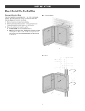
Remove the screws and open the control box. 2. Make sure the control box is level. 1. Secure the control box to ensure a watertight seal. Make sure the U-bolts do not protrude ... (not provided) to mounting surface. INSTALLATION Step 5 Install the Control Box Standard Control Box The control box MUST be mounted within 5 feet (1.52 m) of the gate operator. Select the mounting holes (according to your application) and remove the knockouts using a screwdriver and hammer. 3. Wall or Column: Use the provided screws (4). A. Mount...
Remove the screws and open the control box. 2. Make sure the control box is level. 1. Secure the control box to ensure a watertight seal. Make sure the U-bolts do not protrude ... (not provided) to mounting surface. INSTALLATION Step 5 Install the Control Box Standard Control Box The control box MUST be mounted within 5 feet (1.52 m) of the gate operator. Select the mounting holes (according to your application) and remove the knockouts using a screwdriver and hammer. 3. Wall or Column: Use the provided screws (4). A. Mount...

Installation Manual
Page 15
... Mount the control box as high as possible for the 33AH battery application. 1. Use knock outs located at the 4 corners of the gate operator. Open the control box. Secure the control box to mounting surface with 'U' bolts (refer to chart). TYPE AND SIZE Standard 3" Round Pipe ...Standard 4" Square Post Standard 6" Square Post 'U' BOLT OPENING 3-1/2" 4" 6" 15 The control box door may be removed by opening the door 90°. The control box door may be removed by opening the door 90°. The control box can be mounted within 5 feet (1....
... Mount the control box as high as possible for the 33AH battery application. 1. Use knock outs located at the 4 corners of the gate operator. Open the control box. Secure the control box to mounting surface with 'U' bolts (refer to chart). TYPE AND SIZE Standard 3" Round Pipe ...Standard 4" Square Post Standard 6" Square Post 'U' BOLT OPENING 3-1/2" 4" 6" 15 The control box door may be removed by opening the door 90°. The control box door may be removed by opening the door 90°. The control box can be mounted within 5 feet (1....
Installation Manual
Page 17
...for the other operator. 17 Follow the directions according to be programmed to assign this operator as network primary. 5. Wireless dual gates will light. 7. The yellow NETWORK LED will require the installation of programming mode after 180 seconds. 3. The yellow NETWORK LED...) then turn off indicating successful deactivation. 4. Press and release the OPEN test button to the primary operator. To deactivate the wireless feature: 1. Press and hold the LEARN button for dual gate communication: wired or wireless. Do not use wired and wireless communication ...
...for the other operator. 17 Follow the directions according to be programmed to assign this operator as network primary. 5. Wireless dual gates will light. 7. The yellow NETWORK LED will require the installation of programming mode after 180 seconds. 3. The yellow NETWORK LED...) then turn off indicating successful deactivation. 4. Press and release the OPEN test button to the primary operator. To deactivate the wireless feature: 1. Press and hold the LEARN button for dual gate communication: wired or wireless. Do not use wired and wireless communication ...

Installation Manual
Page 19
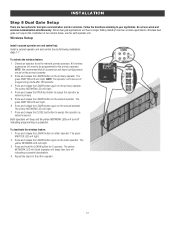
... box): Occasionally in the bottom of the gates, set to open limit. The BIPART DELAY switch on the opposite side to close second. This gate is preferred that side for both control boxes. 19 The illustration shows a dual gate configuration with the BIPART DELAY switch ON will... need to the ON position. Choose a knockout in dual gate installations, one gate to the Gate 1 connector. 1. This would require one gate will delay from the open first and close before the other . To synchronize the closing of the control box. 2. Plug ...
... box): Occasionally in the bottom of the gates, set to open limit. The BIPART DELAY switch on the opposite side to close second. This gate is preferred that side for both control boxes. 19 The illustration shows a dual gate configuration with the BIPART DELAY switch ON will... need to the ON position. Choose a knockout in dual gate installations, one gate to the Gate 1 connector. 1. This would require one gate will delay from the open first and close before the other . To synchronize the closing of the control box. 2. Plug ...
Installation Manual
Page 21
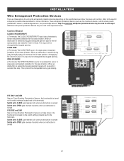
...which include pulsed photoelectric sensors, resistive edge sensors, and pulsed edge sensors. Additional entrapment protection devices may be disregarded during gate opening . This input will be wired to -Close. When an obstruction is for photoelectric sensor or edge sensor entrapment protection... for the close direction. This input will reverse to the full open direction. OPEN EYES/EDGE (2 Terminals) The OPEN EYES/EDGE input is sensed during gate opening the gate will function. CLOSE EDGE (2 Terminals) The CLOSE EDGE input is sensed Switch...
...which include pulsed photoelectric sensors, resistive edge sensors, and pulsed edge sensors. Additional entrapment protection devices may be disregarded during gate opening . This input will be wired to -Close. When an obstruction is for photoelectric sensor or edge sensor entrapment protection... for the close direction. This input will reverse to the full open direction. OPEN EYES/EDGE (2 Terminals) The OPEN EYES/EDGE input is sensed during gate opening the gate will function. CLOSE EDGE (2 Terminals) The CLOSE EDGE input is sensed Switch...
Installation Manual
Page 27
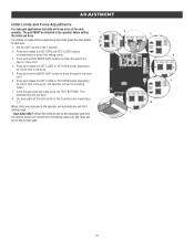
... the force. 8. ADJUSTMENT Initial Limits and Force Adjustments For dual gate applications the limits will have to be attached to the operator before setting the limits and force. Press and release the SET CLOSE or SET OPEN button depending on which limit is being set. 5. Press and ... If a mistake is being set for each operator. Press and hold the MOVE GATE button to move the gate to the other limit. 6. Cycle the gate open or close using the TEST BUTTONS. Press and release the SET OPEN and SET CLOSE buttons simultaneously to the 1 position. 2. Press and hold the MOVE...
... the force. 8. ADJUSTMENT Initial Limits and Force Adjustments For dual gate applications the limits will have to be attached to the operator before setting the limits and force. Press and release the SET CLOSE or SET OPEN button depending on which limit is being set. 5. Press and ... If a mistake is being set for each operator. Press and hold the MOVE GATE button to move the gate to the other limit. 6. Cycle the gate open or close using the TEST BUTTONS. Press and release the SET OPEN and SET CLOSE buttons simultaneously to the 1 position. 2. Press and hold the MOVE...
Installation Manual
Page 31
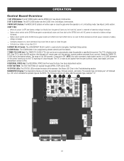
If the TTC is OFF. DIAGNOSTICS Display: The diagnostics display will operate the gate (OPEN, STOP and CLOSE). 10 STATUS LEDs: The STATUS LEDs indicate the status of the operator. See Adjust Limits section. 2 SET CLOSE Button: The SET CLOSE ... type as LA412DC. See Adjust Limits section. 4 BATT FAIL: l When AC power is OFF and battery voltage is critically low the gate will remain open until AC power is for dual gates. See Force Adjustment section. 9 TEST BUTTONS: The TEST BUTTONS will show after a specified time period. The firmware version will close the...
If the TTC is OFF. DIAGNOSTICS Display: The diagnostics display will operate the gate (OPEN, STOP and CLOSE). 10 STATUS LEDs: The STATUS LEDs indicate the status of the operator. See Adjust Limits section. 2 SET CLOSE Button: The SET CLOSE ... type as LA412DC. See Adjust Limits section. 4 BATT FAIL: l When AC power is OFF and battery voltage is critically low the gate will remain open until AC power is for dual gates. See Force Adjustment section. 9 TEST BUTTONS: The TEST BUTTONS will show after a specified time period. The firmware version will close the...
Installation Manual
Page 42
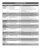
... close with LOW BATT option set e. Edge Sensor does not stop , and may reverse direction. On dual-gate system, incorrect gate opens first or closes first. Close Entrapment Protection Device active a. Vehicle loop detector active b. Defective vehicle loop detector a.... needed a. a. Replace defective photoelectric sensor. Retest that activating edge sensor causes moving gate to stop and reverse. Charge batteries by AC or solar power or replace batteries. Gate closes, but will not open. Low battery with transmitter or Timer-to stop , and may reverse direction. Defective...
... close with LOW BATT option set e. Edge Sensor does not stop , and may reverse direction. On dual-gate system, incorrect gate opens first or closes first. Close Entrapment Protection Device active a. Vehicle loop detector active b. Defective vehicle loop detector a.... needed a. a. Replace defective photoelectric sensor. Retest that activating edge sensor causes moving gate to stop and reverse. Charge batteries by AC or solar power or replace batteries. Gate closes, but will not open. Low battery with transmitter or Timer-to stop , and may reverse direction. Defective...
Installation Manual
Page 45
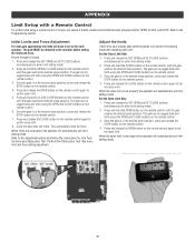
... control. 6. Ensure the gate is set the operator will automatically exit limit setting mode. Cycle the gate open position, press and release the STOP button on the remote control until the gate reaches the desired close . Once the gate is in the desired open and close position. Press ...and hold the OPEN button on the remote control. 4. Press...
... control. 6. Ensure the gate is set the operator will automatically exit limit setting mode. Cycle the gate open position, press and release the STOP button on the remote control until the gate reaches the desired close . Once the gate is in the desired open and close position. Press ...and hold the OPEN button on the remote control. 4. Press...
Installation Manual
Page 50
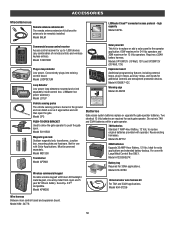
...ground and can detect a car as it approaches and will then open . Model CP3 PUSH-TO-OPEN BRACKET Used to allow the gate operator to push the gate open the gate. Model 50-19503 Magnetic gate lock Outdoor magnetic lock, transformer, junction box, mounting plate and ...battery. ACCESSORIES Miscellaneous Remote antenna extension kit The remote antenna extension kit allows the antenna to be powered separately. Model 86LM LiftMaster Cloud™ connected access protocol - high capacity Model CAPXL Commercial access control receiver Access control receiver for 12 Vdc operators. ...
...ground and can detect a car as it approaches and will then open . Model CP3 PUSH-TO-OPEN BRACKET Used to allow the gate operator to push the gate open the gate. Model 50-19503 Magnetic gate lock Outdoor magnetic lock, transformer, junction box, mounting plate and ...battery. ACCESSORIES Miscellaneous Remote antenna extension kit The remote antenna extension kit allows the antenna to be powered separately. Model 86LM LiftMaster Cloud™ connected access protocol - high capacity Model CAPXL Commercial access control receiver Access control receiver for 12 Vdc operators. ...
LA412PKGU Product Guide
Page 1
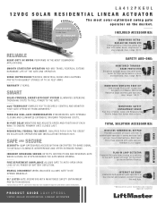
... EDGE KIT Low-energy Bluetooth® connection between a LiftMaster Monitored Resistive Edge and the gate operator; KPW5 BI-PART DELAY MONITORS AND ADJUSTS SPEED AND POSITION OF EACH WING TO ENSURE PRIMARY GATE CLOSES LAST. TOTAL SOLUTION ACCESSORIES: WIRELESS COMMERCIAL KEYPAD Provides... MID-TRAVEL REVERSAL EXTEND HARDWARE LIFE OF THE GATE AND OPERATOR. range: 130 ft.** EDGES myQ TECHNOLOGY ENABLES YOU TO SECURELY CONTROL AND MONITOR YOUR GATE OPERATOR FROM ANYWHERE.* WIRELESS DUAL-GATE COMMUNICATION SYNCHRONIZES GATE OPENING/ CLOSING AND ELIMINATES EXPENSIVE DRIVEWAY TRENCHING COSTS....
... EDGE KIT Low-energy Bluetooth® connection between a LiftMaster Monitored Resistive Edge and the gate operator; KPW5 BI-PART DELAY MONITORS AND ADJUSTS SPEED AND POSITION OF EACH WING TO ENSURE PRIMARY GATE CLOSES LAST. TOTAL SOLUTION ACCESSORIES: WIRELESS COMMERCIAL KEYPAD Provides... MID-TRAVEL REVERSAL EXTEND HARDWARE LIFE OF THE GATE AND OPERATOR. range: 130 ft.** EDGES myQ TECHNOLOGY ENABLES YOU TO SECURELY CONTROL AND MONITOR YOUR GATE OPERATOR FROM ANYWHERE.* WIRELESS DUAL-GATE COMMUNICATION SYNCHRONIZES GATE OPENING/ CLOSING AND ELIMINATES EXPENSIVE DRIVEWAY TRENCHING COSTS....


