Installation Manual
Page 2
... MAINTENANCE 36 Important Safety Instructions 36 Maintenance Chart 36 Batteries 36 TROUBLESHOOTING 37 Diagnostic Codes 37 Diagnostic Codes Table 38 Control Board LEDs 40 Troubleshooting Chart 41 APPENDIX 44 Bracket Types 44 Limit Setup with a Remote Control 45 REPAIR PARTS 46 Standard Control Box 46 Gate Operator Arm 46 WIRING DIAGRAM 47 Standard Control Box 47 Large Metal Control Box 48 ACCESSORIES 49 WARRANTY 51 TEMPLATE FOR POST BRACKET MOUNTING 52 SAFETY Safety Symbol and Signal Word Review When you see this manual and follow all safety instructions...
... MAINTENANCE 36 Important Safety Instructions 36 Maintenance Chart 36 Batteries 36 TROUBLESHOOTING 37 Diagnostic Codes 37 Diagnostic Codes Table 38 Control Board LEDs 40 Troubleshooting Chart 41 APPENDIX 44 Bracket Types 44 Limit Setup with a Remote Control 45 REPAIR PARTS 46 Standard Control Box 46 Gate Operator Arm 46 WIRING DIAGRAM 47 Standard Control Box 47 Large Metal Control Box 48 ACCESSORIES 49 WARRANTY 51 TEMPLATE FOR POST BRACKET MOUNTING 52 SAFETY Safety Symbol and Signal Word Review When you see this manual and follow all safety instructions...
Installation Manual
Page 3
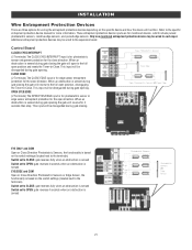
... of gate travel , retest the gate operator. Read the owner's manual. IMPORTANT SAFETY INSTRUCTIONS To reduce the risk of two independent* monitored entrapment protection devices in each entrapment zone l Every installation is unique. Failure to install external monitored entrapment protection devices in either the open or close direction. l SAVE THESE INSTRUCTIONS. 3 Have a qualified service person make repairs to service the general public. Industrial/Limited Access Vehicular Gate A vehicular gate operator (or...
... of gate travel , retest the gate operator. Read the owner's manual. IMPORTANT SAFETY INSTRUCTIONS To reduce the risk of two independent* monitored entrapment protection devices in each entrapment zone l Every installation is unique. Failure to install external monitored entrapment protection devices in either the open or close direction. l SAVE THESE INSTRUCTIONS. 3 Have a qualified service person make repairs to service the general public. Industrial/Limited Access Vehicular Gate A vehicular gate operator (or...

Installation Manual
Page 4
... directions prior to prevent unauthorized use conditions. The pedestrian access opening and closing to promote pedestrian usage. SAFETY Safety Installation Information 1. The Stop and/or Reset (if provided separately) must be located where the transmission of the gate. application. 10. One or more contact sensors shall be located in its wiring arranged so the communication between the gate and adjacent structures when opening shall be incorporated into...
... directions prior to prevent unauthorized use conditions. The pedestrian access opening and closing to promote pedestrian usage. SAFETY Safety Installation Information 1. The Stop and/or Reset (if provided separately) must be located where the transmission of the gate. application. 10. One or more contact sensors shall be located in its wiring arranged so the communication between the gate and adjacent structures when opening shall be incorporated into...
Installation Manual
Page 17
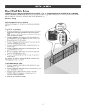
... not use wired and wireless communication simultaneously. The yellow NETWORK LED will light. 3. Both operators will beep and the yellow NETWORK LEDs will beep) then turn off indicating successful deactivation. 4. Press and release the LEARN button again on the second operator. All wireless accessories will time out of two control boxes, one for dual gate communication: wired or wireless. INSTALLATION Step 8 Dual Gate Setup There are set on the primary operator. 2. Wireless Setup Install a second operator arm and control box: Install a second operator arm and control box by...
... not use wired and wireless communication simultaneously. The yellow NETWORK LED will light. 3. Both operators will beep and the yellow NETWORK LEDs will beep) then turn off indicating successful deactivation. 4. Press and release the LEARN button again on the second operator. All wireless accessories will time out of two control boxes, one for dual gate communication: wired or wireless. INSTALLATION Step 8 Dual Gate Setup There are set on the primary operator. 2. Wireless Setup Install a second operator arm and control box: Install a second operator arm and control box by...
Installation Manual
Page 21
... reverse for 4 seconds then stop. OPEN EYES/EDGE (2 Terminals) The OPEN EYES/EDGE input is based on the specific device and how the device will function. EYE ONLY and COM Open or Close Direction Photoelectric Sensors, the functionality is based on the switch settings (located next to the terminals) Switch set to CLOSE: gate reverses fully when an obstruction is sensed Switch set to each input. Refer to -Close. Control Board CLOSES EYES/INTERRUPT (2 Terminals) The CLOSE EYES...
... reverse for 4 seconds then stop. OPEN EYES/EDGE (2 Terminals) The OPEN EYES/EDGE input is based on the specific device and how the device will function. EYE ONLY and COM Open or Close Direction Photoelectric Sensors, the functionality is based on the switch settings (located next to the terminals) Switch set to CLOSE: gate reverses fully when an obstruction is sensed Switch set to each input. Refer to -Close. Control Board CLOSES EYES/INTERRUPT (2 Terminals) The CLOSE EYES...
Installation Manual
Page 29
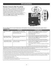
.... 3. PROGRAMMING Remote Controls (Not Provided) A total of the remote controls DO NOT straighten the antenna. Press and release the LEARN button (operator will beep and green XMITTER LED will light). NOTE: If installing an 86LM to extend the range of 50 Security+ 2.0® remote controls or KPW250 keypads and 2 keyless entries (1 PIN for compliance could void the user's authority to function. NOTE: The operator will time out of programming mode after 30 seconds. 2. Press and release the LEARN button (operator will beep and green...
.... 3. PROGRAMMING Remote Controls (Not Provided) A total of the remote controls DO NOT straighten the antenna. Press and release the LEARN button (operator will beep and green XMITTER LED will light). NOTE: If installing an 86LM to extend the range of 50 Security+ 2.0® remote controls or KPW250 keypads and 2 keyless entries (1 PIN for compliance could void the user's authority to function. NOTE: The operator will time out of programming mode after 30 seconds. 2. Press and release the LEARN button (operator will beep and green...
Installation Manual
Page 30
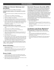
... controlled through the LiftMaster Internet Gateway app. External entrapment protection devices include LiftMaster monitored photoelectric sensors and LiftMaster monitored wired and wireless edge sensors. Remove the entrapment protection device wires from the terminal block. 2. The gate operator can only be either the operator reaches a limit or the user releases #. Use the feature only in learn mode). Press and release both the SET OPEN and SET CLOSE LEDs blink rapidly and the operator beeps. 2. Release the buttons and the SET OPEN and SET CLOSE LEDs will blink...
... controlled through the LiftMaster Internet Gateway app. External entrapment protection devices include LiftMaster monitored photoelectric sensors and LiftMaster monitored wired and wireless edge sensors. Remove the entrapment protection device wires from the terminal block. 2. The gate operator can only be either the operator reaches a limit or the user releases #. Use the feature only in learn mode). Press and release both the SET OPEN and SET CLOSE LEDs blink rapidly and the operator beeps. 2. Release the buttons and the SET OPEN and SET CLOSE LEDs will blink...
Installation Manual
Page 31
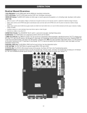
... gate (OPEN, STOP and CLOSE). 10 STATUS LEDs: The STATUS LEDs indicate the status of the operator. The TTC is OFF. NOTE: Any radio command, single button control, or CLOSE command on next CLOSE command until the operator receives another command from the open until AC power restored or battery voltage increases. See Status LED Chart in Limit setting mode. OPERATION Control Board Overview 1 SET OPEN Button: The SET OPEN button sets the OPEN limit. See Force Adjustment section. 9 TEST BUTTONS: The TEST BUTTONS will show after a specified time...
... gate (OPEN, STOP and CLOSE). 10 STATUS LEDs: The STATUS LEDs indicate the status of the operator. The TTC is OFF. NOTE: Any radio command, single button control, or CLOSE command on next CLOSE command until the operator receives another command from the open until AC power restored or battery voltage increases. See Status LED Chart in Limit setting mode. OPERATION Control Board Overview 1 SET OPEN Button: The SET OPEN button sets the OPEN limit. See Force Adjustment section. 9 TEST BUTTONS: The TEST BUTTONS will show after a specified time...
Installation Manual
Page 32
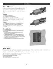
... AC/ battery power (the operator will activate then turn off the alarm and reset the operator. This locks the release lever. 3. Reset Button The reset button is in manual mode and the gate can also be opened and closed manually. To restart the Timer-toClose either press the reset button or activate the gate with a programmed remote control. OPERATION Manual Release In case of the following to restart the gate: 1. Turn the key counter-clockwise 180°. 3. Party Mode Press the reset button once...
... AC/ battery power (the operator will activate then turn off the alarm and reset the operator. This locks the release lever. 3. Reset Button The reset button is in manual mode and the gate can also be opened and closed manually. To restart the Timer-toClose either press the reset button or activate the gate with a programmed remote control. OPERATION Manual Release In case of the following to restart the gate: 1. Turn the key counter-clockwise 180°. 3. Party Mode Press the reset button once...
Installation Manual
Page 36
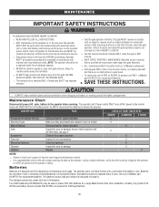
... two 7AH batteries. Read the owner's manual. The operator's AC Power switch ONLY turns off AC power to service the operator. l It is properly adjusted and there are no obstructions to be replaced every 3 years. l Test the gate operator monthly. l Use the manual disconnect release ONLY when the gate is low. l Activate gate ONLY when it still complies with l KEEP GATES PROPERLY MAINTAINED. SAVE THESE INSTRUCTIONS. Maintenance Chart Disconnect all wire connections Check for...
... two 7AH batteries. Read the owner's manual. The operator's AC Power switch ONLY turns off AC power to service the operator. l It is properly adjusted and there are no obstructions to be replaced every 3 years. l Test the gate operator monthly. l Use the manual disconnect release ONLY when the gate is low. l Activate gate ONLY when it still complies with l KEEP GATES PROPERLY MAINTAINED. SAVE THESE INSTRUCTIONS. Maintenance Chart Disconnect all wire connections Check for...
Installation Manual
Page 38
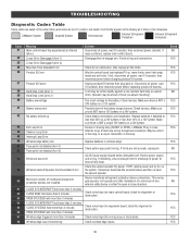
... power. If not, disconnect all power, wait 15 seconds, then reconnect power before changing product ID harness. Disconnect all power, wait 15 seconds, then reconnect power before replacing product ID harness. Operator may be a short in the loop, or an open or close direction. Review power supply and wiring. If powered, deactivate the wireless feature and then re-learn the second operator. TROUBLESHOOTING Diagnostic Codes Table Some codes are saved in wireless edge. CLOSE EYE...
... power. If not, disconnect all power, wait 15 seconds, then reconnect power before changing product ID harness. Disconnect all power, wait 15 seconds, then reconnect power before replacing product ID harness. Operator may be a short in the loop, or an open or close direction. Review power supply and wiring. If powered, deactivate the wireless feature and then re-learn the second operator. TROUBLESHOOTING Diagnostic Codes Table Some codes are saved in wireless edge. CLOSE EYE...
Installation Manual
Page 39
... close, or resetting TTC CLOSE EYE/EDGE triggered, causing reversal and preventing close or canceling TTC OPEN EYE/EDGE triggered, causing reversal or preventing opening Close input (EYE/EDGE) communication fault from other operator Open input (EYE/EDGE) communication fault from other operator Close input (EYE/EDGE) communication fault (expansion board) Open input (EYE/EDGE) communication fault (expansion board) Non-monitored device detected on the wireless safety system Force Reversal (Operator 1) Force Reversal (Operator 2) RPM / STALL Reversal (Operator 1) RPM / STALL Reversal (Operator...
... close, or resetting TTC CLOSE EYE/EDGE triggered, causing reversal and preventing close or canceling TTC OPEN EYE/EDGE triggered, causing reversal or preventing opening Close input (EYE/EDGE) communication fault from other operator Open input (EYE/EDGE) communication fault from other operator Close input (EYE/EDGE) communication fault (expansion board) Open input (EYE/EDGE) communication fault (expansion board) Non-monitored device detected on the wireless safety system Force Reversal (Operator 1) Force Reversal (Operator 2) RPM / STALL Reversal (Operator 1) RPM / STALL Reversal (Operator...
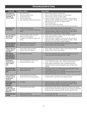
Installation Manual
Page 42
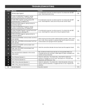
... detector setup incorrectly b. Double entrapment occurred (two obstructions within a single activation) a. Check if AC power is available. Review Exit loop detector settings. b. Review Interrupt loop detector settings. Review Shadow loop detector settings. Check photoelectric sensor wiring. Replace defective edge sensor. Press the reset button to -Close (TTC) setting g. Constant pressure to open limit. Vehicle loop detector active c. Low battery with a command. Defective vehicle loop detector a. Force adjustment needed . Incorrect Bipart switch setting...
... detector setup incorrectly b. Double entrapment occurred (two obstructions within a single activation) a. Check if AC power is available. Review Exit loop detector settings. b. Review Interrupt loop detector settings. Review Shadow loop detector settings. Check photoelectric sensor wiring. Replace defective edge sensor. Press the reset button to -Close (TTC) setting g. Constant pressure to open limit. Vehicle loop detector active c. Low battery with a command. Defective vehicle loop detector a. Force adjustment needed . Incorrect Bipart switch setting...
Installation Manual
Page 50
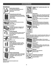
... a car as it approaches and will then open . Model LOOPDETLM Loop Detector Low power loop detectors mounted and wired separately inside control box. Model 50-19503 Magnetic gate lock Outdoor magnetic lock, transformer, junction box, mounting plate and hardware. Two identical 12 Vdc batteries are required for 12 Vdc operators. Model CP3 PUSH-TO-OPEN BRACKET Used to allow the gate operator to the operator application. 60W maximum for 24 Vdc operators and 30W maximum for each gate operator. Model MG1300 Transformer Model APOW3 Wireless commercial keypad Durable wireless keypad...
... a car as it approaches and will then open . Model LOOPDETLM Loop Detector Low power loop detectors mounted and wired separately inside control box. Model 50-19503 Magnetic gate lock Outdoor magnetic lock, transformer, junction box, mounting plate and hardware. Two identical 12 Vdc batteries are required for 12 Vdc operators. Model CP3 PUSH-TO-OPEN BRACKET Used to allow the gate operator to the operator application. 60W maximum for 24 Vdc operators and 30W maximum for each gate operator. Model MG1300 Transformer Model APOW3 Wireless commercial keypad Durable wireless keypad...
Installation Manual
Page 51
... THIS PRODUCT), LABOR CHARGES FOR REINSTALLING A REPAIRED OR REPLACED UNIT, OR REPLACEMENT OF BATTERIES. THIS LIMITED WARRANTY ALSO DOES NOT COVER ANY PROBLEMS CAUSED BY INTERFERENCE. Products returned to Seller for warranty repair, which upon receipt by Seller are confirmed to be repaired or replaced with the instructions regarding installation, operation, maintenance and testing. ANY SERVICE CALL THAT DETERMINES THE PROBLEM HAS BEEN CAUSED BY ANY OF...
... THIS PRODUCT), LABOR CHARGES FOR REINSTALLING A REPAIRED OR REPLACED UNIT, OR REPLACEMENT OF BATTERIES. THIS LIMITED WARRANTY ALSO DOES NOT COVER ANY PROBLEMS CAUSED BY INTERFERENCE. Products returned to Seller for warranty repair, which upon receipt by Seller are confirmed to be repaired or replaced with the instructions regarding installation, operation, maintenance and testing. ANY SERVICE CALL THAT DETERMINES THE PROBLEM HAS BEEN CAUSED BY ANY OF...
LA412UL Wiring Diagram
Page 1
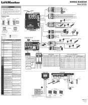
... battery connections and installation. GATE STATE AUX RELAY 1 SWITCHES 1 OFF 2 OFF 3 OFF CLOSED Red light OFF* AUX RELAY 2 SWITCHES 1 ON 2 ON 3 ON Green light OFF OPENING Red light ON/FLASH Green light OFF OPEN CLOSING Red light OFF Red light ON/FLASH Green light ON Green light OFF SHADOW INTERUPT EXIT Shadow Loop DIAGNOSOTINCS ON OFF Energizes with AC or solar power Energizes with battery power ON OFF ON Energizes when gate is Energizes when gate is on on a 12V system. CODE COLOR KEY: LiftMaster System Installed System Informational CODE NUMBER The second number...
... battery connections and installation. GATE STATE AUX RELAY 1 SWITCHES 1 OFF 2 OFF 3 OFF CLOSED Red light OFF* AUX RELAY 2 SWITCHES 1 ON 2 ON 3 ON Green light OFF OPENING Red light ON/FLASH Green light OFF OPEN CLOSING Red light OFF Red light ON/FLASH Green light ON Green light OFF SHADOW INTERUPT EXIT Shadow Loop DIAGNOSOTINCS ON OFF Energizes with AC or solar power Energizes with battery power ON OFF ON Energizes when gate is Energizes when gate is on on a 12V system. CODE COLOR KEY: LiftMaster System Installed System Informational CODE NUMBER The second number...
LA412UL Product Data Sheet
Page 1
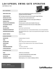
... chart for specific details) Precision machined all-metal gear drive Rated for gates up to 850 lbs. LA412PKGUL SWING GATE OPERATOR SECTION 32 31 00 KEY FEATURES REMOTE CONTROL ACCESS Security+ 2.0® 3-channel receiver will handle up to 140°F (60°C) UL USAGE CLASSIFICATION UL 325 & UL 991 listed - Reference detailed solar chart on product page at LiftMaster.com DIAGNOSTIC DISPLAY LED diagnostic display WIRELESS DUAL-GATE COMMUNICATION...
... chart for specific details) Precision machined all-metal gear drive Rated for gates up to 850 lbs. LA412PKGUL SWING GATE OPERATOR SECTION 32 31 00 KEY FEATURES REMOTE CONTROL ACCESS Security+ 2.0® 3-channel receiver will handle up to 140°F (60°C) UL USAGE CLASSIFICATION UL 325 & UL 991 listed - Reference detailed solar chart on product page at LiftMaster.com DIAGNOSTIC DISPLAY LED diagnostic display WIRELESS DUAL-GATE COMMUNICATION...

LA412PKGU Product Guide
Page 1
... PRIMARY GATE CLOSES LAST. INHERENT REVERSING SENSOR DETECTS OBSTRUCTIONS AND REVERSES GATE WHEN CLOSING OR STOPS/REVERSES THE GATE WHEN OPENING. INCLUDED ACCESSORIES: MONITORED RETROREFLECTIVE PHOTO EYE Enhanced retro-reflective photo eye now with gate operator firmware 4.2 or higher. max. SAFE AND SECURE SECURITY+ 2.0® SAFEGUARDS ACCESS WITH AN ENCRYPTED TRI-BAND SIGNAL TO VIRTUALLY ELIMINATE INTERFERENCE AND OFFER EXTENDED RANGE. Hold Open/ Party Pass enabled with wider beam, engineered to stay aligned; PLUG-IN LOOP DETECTOR Prevents the gate...
... PRIMARY GATE CLOSES LAST. INHERENT REVERSING SENSOR DETECTS OBSTRUCTIONS AND REVERSES GATE WHEN CLOSING OR STOPS/REVERSES THE GATE WHEN OPENING. INCLUDED ACCESSORIES: MONITORED RETROREFLECTIVE PHOTO EYE Enhanced retro-reflective photo eye now with gate operator firmware 4.2 or higher. max. SAFE AND SECURE SECURITY+ 2.0® SAFEGUARDS ACCESS WITH AN ENCRYPTED TRI-BAND SIGNAL TO VIRTUALLY ELIMINATE INTERFERENCE AND OFFER EXTENDED RANGE. Hold Open/ Party Pass enabled with wider beam, engineered to stay aligned; PLUG-IN LOOP DETECTOR Prevents the gate...

Instructions
Page 2
This documentation contains information proprietary to LiftMaster. FOR TECHNICAL SUPPORT TO ORDER REPAIR PARTS Call our toll free numbers: Call our toll free numbers: (800) 323-2276 (800) 998-9197 (800) 528-2806 (800) 998-9197 Installation and service information is protected by copyright and contain information proprietary to LiftMaster and such information may not be distributed without the prior written consent of LiftMaster. Prepare to this documentation...
This documentation contains information proprietary to LiftMaster. FOR TECHNICAL SUPPORT TO ORDER REPAIR PARTS Call our toll free numbers: Call our toll free numbers: (800) 323-2276 (800) 998-9197 (800) 528-2806 (800) 998-9197 Installation and service information is protected by copyright and contain information proprietary to LiftMaster and such information may not be distributed without the prior written consent of LiftMaster. Prepare to this documentation...
Installation Blueprint
Page 1
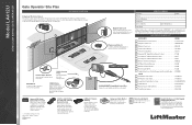
... (batteries not included). Customer: Project: Architect/Engineer: Contractor: Gate Length (ft.): Solar (Y/N): ORDER SUMMARY Date: Gate Weight (lbs.): LiftMaster gate operators comply with this operator. Model LMRRU is simple to -Open Bracket 50-19503 Vehicle Sensing Probe 50-CP3 Universal DIP Single Button Remote Control 811LM Security+ 2.0® 2-Button Remote Control 892LT Security+ 2.0® 4-Button Remote Control 894LT Wireless Commercial Keypad KPW250 LiftMaster Internet Gateway 828LM Garage and Gate Monitor 829LM Remote Light Switch 823LM Single Entry Access...
... (batteries not included). Customer: Project: Architect/Engineer: Contractor: Gate Length (ft.): Solar (Y/N): ORDER SUMMARY Date: Gate Weight (lbs.): LiftMaster gate operators comply with this operator. Model LMRRU is simple to -Open Bracket 50-19503 Vehicle Sensing Probe 50-CP3 Universal DIP Single Button Remote Control 811LM Security+ 2.0® 2-Button Remote Control 892LT Security+ 2.0® 4-Button Remote Control 894LT Wireless Commercial Keypad KPW250 LiftMaster Internet Gateway 828LM Garage and Gate Monitor 829LM Remote Light Switch 823LM Single Entry Access...


