
LA100 Linear Gate Operator Manual
Page 1
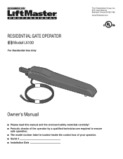
RESIDENTIAL GATE OPERATOR Model LA100 For Residential Use Only The Chamberlain Group, Inc. 845 Larch Avenue Elmhurst, Illinois 60126-1196 www.liftmaster.com Owner's Manual ■ Please read this manual and the enclosed safety materials carefully! ■ Periodic checks of the operator by a qualified technician are required to ensure safe operation. ■ The model number label is located inside the control box of your operator. ■ Serial # ■ Installation Date
RESIDENTIAL GATE OPERATOR Model LA100 For Residential Use Only The Chamberlain Group, Inc. 845 Larch Avenue Elmhurst, Illinois 60126-1196 www.liftmaster.com Owner's Manual ■ Please read this manual and the enclosed safety materials carefully! ■ Periodic checks of the operator by a qualified technician are required to ensure safe operation. ■ The model number label is located inside the control box of your operator. ■ Serial # ■ Installation Date
LA100 Linear Gate Operator Manual
Page 2
...-17 INSTALLATION 10-12 Mount the Control Box and Power Supply 13-17 Attach Operator to Gate 18-20 WIRING 18-20 Connect Gate Operator to Control Box 21-25 21 21-22 23 24 25 25 PROGRAMMING Before You Begin Programming Gate Travel (Limit Learn) Adding Additional Wireless Control Devices Safety Sensor Connections The Protector System® Entrapment Zone Safety Sensor Protection 26-28 OPERATION AND MAINTENANCE 26 Important Safety Information 26 Operation 27 Manual Release 27 Maintenance 28 Troubleshooting 29-30 REPAIR PARTS 29 Control Box 29 Gate Operator...
...-17 INSTALLATION 10-12 Mount the Control Box and Power Supply 13-17 Attach Operator to Gate 18-20 WIRING 18-20 Connect Gate Operator to Control Box 21-25 21 21-22 23 24 25 25 PROGRAMMING Before You Begin Programming Gate Travel (Limit Learn) Adding Additional Wireless Control Devices Safety Sensor Connections The Protector System® Entrapment Zone Safety Sensor Protection 26-28 OPERATION AND MAINTENANCE 26 Important Safety Information 26 Operation 27 Manual Release 27 Maintenance 28 Troubleshooting 29-30 REPAIR PARTS 29 Control Box 29 Gate Operator...
LA100 Linear Gate Operator Manual
Page 3
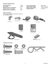
... 3/8"-16 (1) Serrated Flange Nut 5/16"-18 (1) RIbbed Neck Bolt 3/8"-16x1-1/2" (1) Pin (1) SECURITY✚® 3-Button Remote Control (1) HairPin Clip (2) 3 Introduction Gate may move at any time without prior warning. Power Supply Voltage: Maximum Gate Weight: Maximum Gate Length: Operating Cycles: 24Vac, 50VA 250 lbs. (113.4 kg) 12' (3.7 m) length 20 per day Post Bracket (1) Extension Bracket (1) Gate Bracket (1) Power Supply (1) Control Box (1) Moving Gate Can Cause Injury or Death KEEP CLEAR!
... 3/8"-16 (1) Serrated Flange Nut 5/16"-18 (1) RIbbed Neck Bolt 3/8"-16x1-1/2" (1) Pin (1) SECURITY✚® 3-Button Remote Control (1) HairPin Clip (2) 3 Introduction Gate may move at any time without prior warning. Power Supply Voltage: Maximum Gate Weight: Maximum Gate Length: Operating Cycles: 24Vac, 50VA 250 lbs. (113.4 kg) 12' (3.7 m) length 20 per day Post Bracket (1) Extension Bracket (1) Gate Bracket (1) Power Supply (1) Control Box (1) Moving Gate Can Cause Injury or Death KEEP CLEAR!
LA100 Linear Gate Operator Manual
Page 4
... washers, lock washers and lock nuts. The gate bracket can then be : 5/16-18 x 3" hex head bolt with circular rails, it is best to attach a vertical support panel connecting the top rail to this vertical panel using the same bolts, washers and nuts as illustrated below. THE PROTECTOR SYSTEM® SAFETY SENSORS Two pair of the operator, instructions will call for more information. For gates with fl...
... washers, lock washers and lock nuts. The gate bracket can then be : 5/16-18 x 3" hex head bolt with circular rails, it is best to attach a vertical support panel connecting the top rail to this vertical panel using the same bolts, washers and nuts as illustrated below. THE PROTECTOR SYSTEM® SAFETY SENSORS Two pair of the operator, instructions will call for more information. For gates with fl...
LA100 Linear Gate Operator Manual
Page 5
... wiring arranged so that operates the gate operator where the user can create high levels of force during the entire travel of the gate, or easily accessible controls shall have a security feature to prevent unauthorized use in a location so that persons will not come in both directions prior to operate the controls. A gate operator can reach over, under, around or through the gate to the installation of a moving vehicular gate...
... wiring arranged so that operates the gate operator where the user can create high levels of force during the entire travel of the gate, or easily accessible controls shall have a security feature to prevent unauthorized use in a location so that persons will not come in both directions prior to operate the controls. A gate operator can reach over, under, around or through the gate to the installation of a moving vehicular gate...
LA100 Linear Gate Operator Manual
Page 6
... Injury or Death KEEP CLEAR! This entrance is provided with two safety warning placards. The placards may move at any time without prior warning. Gate may be mounted using fastening holes. 13. Each gate operator is for vehicles only. SAVE THE INSTRUCTIONS. To AVOID damaging gas, power, or other underground utility lines, contact underground utility locating companies BEFORE digging. 14.
... Injury or Death KEEP CLEAR! This entrance is provided with two safety warning placards. The placards may move at any time without prior warning. Gate may be mounted using fastening holes. 13. Each gate operator is for vehicles only. SAVE THE INSTRUCTIONS. To AVOID damaging gas, power, or other underground utility lines, contact underground utility locating companies BEFORE digging. 14.
LA100 Linear Gate Operator Manual
Page 10
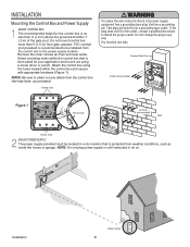
Select mounting holes within the control box and secure with appropriate hardware (Figure 1). Attach the control box using a screw driver or punch. Remove the cover screws (4) then set cover aside. Do not change the plug in the outlet, contact a qualified electrician to do so. NOTE: Do not plug power supply in a dry location that is best suited for the control box is no less than 5' (1.5 m) from gate operator. KpPtDTiMlmheEoadiEyseneoPioeswnnttvCirtttliLiehrhaIanEteonnncAusggjchtRaumeiplt!GdeirursGriysoaeaaftrrnotetueorwaoesmv.rapeereaChnsDryeiiacnaptmelgeean....
Select mounting holes within the control box and secure with appropriate hardware (Figure 1). Attach the control box using a screw driver or punch. Remove the cover screws (4) then set cover aside. Do not change the plug in the outlet, contact a qualified electrician to do so. NOTE: Do not plug power supply in a dry location that is best suited for the control box is no less than 5' (1.5 m) from gate operator. KpPtDTiMlmheEoadiEyseneoPioeswnnttvCirtttliLiehrhaIanEteonnncAusggjchtRaumeiplt!GdeirursGriysoaeaaftrrnotetueorwaoesmv.rapeereaChnsDryeiiacnaptmelgeean....
LA100 Linear Gate Operator Manual
Page 11
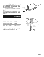
MOUNT POWER SUPPLY (CONTINUED) • Connect and firmly secure 2 conductor wires to 'Wire Table' for recommended wire size and distance from the power supply and the gate operator control box (Figure 2). • Pull wire through one of the water tight connector nuts located on the bottom of the control box. Tighten nut firmly. Figure 3 24VAC Control Box Watertight Connector Nut Operator Cable 11 Installation Refer to the terminals marked...
MOUNT POWER SUPPLY (CONTINUED) • Connect and firmly secure 2 conductor wires to 'Wire Table' for recommended wire size and distance from the power supply and the gate operator control box (Figure 2). • Pull wire through one of the water tight connector nuts located on the bottom of the control box. Tighten nut firmly. Figure 3 24VAC Control Box Watertight Connector Nut Operator Cable 11 Installation Refer to the terminals marked...

LA100 Linear Gate Operator Manual
Page 15
.... The post bracket assembly can be exact in all installations. Gate Operator Gate Bracket 5-1/2" Marked Location Clamp 1/4" Gap 15 Installation Pin Post Bracket Hairpin Clip Gate Bracket Hairpin Clip 5 POSITION OPERATOR ON MOUNTING LOCATION Before proceeding, begin with the clamps. • Ensure the operator is at least 4" (10 cm) off the ground. • Temporarily secure the post bracket to the post and the gate bracket to the gate operator using the pin and the hairpin...
.... The post bracket assembly can be exact in all installations. Gate Operator Gate Bracket 5-1/2" Marked Location Clamp 1/4" Gap 15 Installation Pin Post Bracket Hairpin Clip Gate Bracket Hairpin Clip 5 POSITION OPERATOR ON MOUNTING LOCATION Before proceeding, begin with the clamps. • Ensure the operator is at least 4" (10 cm) off the ground. • Temporarily secure the post bracket to the post and the gate bracket to the gate operator using the pin and the hairpin...
LA100 Linear Gate Operator Manual
Page 18
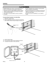
... wiring diagram. • ALL power wiring should be made by a qualified individual. • DO NOT install ANY wiring or attempt to follow ALL specifications and warnings described below. • Disconnect the power supply BEFORE proceeding. Operator MUST be properly grounded and connected in accordance with local electrical codes. • ALL electrical connections MUST be visible and clearly labeled. • cAoLnLdpuoi tw. The location of the control box...
... wiring diagram. • ALL power wiring should be made by a qualified individual. • DO NOT install ANY wiring or attempt to follow ALL specifications and warnings described below. • Disconnect the power supply BEFORE proceeding. Operator MUST be properly grounded and connected in accordance with local electrical codes. • ALL electrical connections MUST be visible and clearly labeled. • cAoLnLdpuoi tw. The location of the control box...
LA100 Linear Gate Operator Manual
Page 20
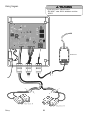
Q7 C38 C98 D16 C42 S2 K2 LEARN / CLOSE MODE / OPEN MIN R17 S1 RESET JU1 R6 GATE FORCE U2 U2 127A0154P6 2007 36 MAX +_ _+ IR SWITCH BLU RED WHT BRN GRN YEL 24VAC MOV1 D20 K1 Power Supply 12V COM 24V ALARM Wiring Safety Sensors (IR) 20 Safety Sensors (IR) Wiring Diagram To protect against fire and electrocution: • DISCONNECT power BEFORE installing or servicing operator.
Q7 C38 C98 D16 C42 S2 K2 LEARN / CLOSE MODE / OPEN MIN R17 S1 RESET JU1 R6 GATE FORCE U2 U2 127A0154P6 2007 36 MAX +_ _+ IR SWITCH BLU RED WHT BRN GRN YEL 24VAC MOV1 D20 K1 Power Supply 12V COM 24V ALARM Wiring Safety Sensors (IR) 20 Safety Sensors (IR) Wiring Diagram To protect against fire and electrocution: • DISCONNECT power BEFORE installing or servicing operator.
LA100 Linear Gate Operator Manual
Page 21
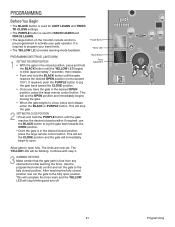
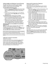
... the force learn and the YELLOW LED will be blinking. LEARN / CLOSE MODE / OPEN RESET R17 S1 D16 C42 S2 MIN GATE FORCE 21 Programming U2 C38 C98 MAX PROGRAMMING Before You Begin • The BLACK button is used for LIMIT LEARN and TIMER TO CLOSE settings. • The PURPLE button is used for RADIO LEARN and FORCE LEARN. • The large button on the 3-button remote control is pre-programmed to program your gate operator. Purple Button Yellow LED Black Button Force Adjustment Allow gate to open position. It is free...
... the force learn and the YELLOW LED will be blinking. LEARN / CLOSE MODE / OPEN RESET R17 S1 D16 C42 S2 MIN GATE FORCE 21 Programming U2 C38 C98 MAX PROGRAMMING Before You Begin • The BLACK button is used for LIMIT LEARN and TIMER TO CLOSE settings. • The PURPLE button is used for RADIO LEARN and FORCE LEARN. • The large button on the 3-button remote control is pre-programmed to program your gate operator. Purple Button Yellow LED Black Button Force Adjustment Allow gate to open position. It is free...
LA100 Linear Gate Operator Manual
Page 22
... the Gate Force control set too light, gate travel and learn limit have been programmed as stated above . The next command given will make the gate travel limits) is obtained to MIN, place the cardboard container against the close gate. • NEVER use force adjustments to MIN, place the cardboard container the gate operator was shipped in against an entrapment area on the control board. Gate MUST reverse on the remote control. When the gate is traveling and...
... the Gate Force control set too light, gate travel and learn limit have been programmed as stated above . The next command given will make the gate travel limits) is obtained to MIN, place the cardboard container against the close gate. • NEVER use force adjustments to MIN, place the cardboard container the gate operator was shipped in against an entrapment area on the control board. Gate MUST reverse on the remote control. When the gate is traveling and...
LA100 Linear Gate Operator Manual
Page 23
... device must accept any electrical connections to learn a new remote control. 2. To add Keyless Entry Control (not provided): 1. Within 30 seconds enter a four digit personal identification number (PIN) then press the ENTER button for 2 seconds then release when the YELLOW LED turns on solid and then go out. (Temporary PIN's are not available for use with this gate operator) NOTE: If no radio signal is a user programmable option that...
... device must accept any electrical connections to learn a new remote control. 2. To add Keyless Entry Control (not provided): 1. Within 30 seconds enter a four digit personal identification number (PIN) then press the ENTER button for 2 seconds then release when the YELLOW LED turns on solid and then go out. (Temporary PIN's are not available for use with this gate operator) NOTE: If no radio signal is a user programmable option that...
LA100 Linear Gate Operator Manual
Page 24
... a car. Start with the gate from the system. To reset the control board: • Remove Power Supply. • Remove all Sensor wires from entrapping an individual. The safety sensors are misaligned. Disconnect the Power Supply. 2. Connect the RED sensor wires to the "IR+" terminal and the BLACK sensor wires to the control box: 1. R6 R17 RESET JU1 ALARM +_ _+ IR SWITCH +_ _+ IR SWITCH When connected properly and with the sensors aligned properly, both of wire leads. if the sensors...
... a car. Start with the gate from the system. To reset the control board: • Remove Power Supply. • Remove all Sensor wires from entrapping an individual. The safety sensors are misaligned. Disconnect the Power Supply. 2. Connect the RED sensor wires to the "IR+" terminal and the BLACK sensor wires to the control box: 1. R6 R17 RESET JU1 ALARM +_ _+ IR SWITCH +_ _+ IR SWITCH When connected properly and with the sensors aligned properly, both of wire leads. if the sensors...
LA100 Linear Gate Operator Manual
Page 26
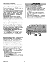
... service person make repairs to adjust and retest the gate operator properly can AVERTISSSEAMVEENTTHESE increase the risk of the remote control button will stop on the control box. During the close limit setting. moving in the same direction. Use the emergency release ONLY when the gate is for 5 minutes, alerting the user of a possible problem. gate hardware. 4. To resume normal operation, the user must remove the obstruction and then press the RESET button located on the open and...
... service person make repairs to adjust and retest the gate operator properly can AVERTISSSEAMVEENTTHESE increase the risk of the remote control button will stop on the control box. During the close limit setting. moving in the same direction. Use the emergency release ONLY when the gate is for 5 minutes, alerting the user of a possible problem. gate hardware. 4. To resume normal operation, the user must remove the obstruction and then press the RESET button located on the open and...
LA100 Linear Gate Operator Manual
Page 27
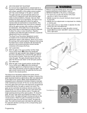
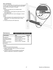
... a mechanical gate lock is observed or suspected. 27 Operation and Maintenance Align the traveler on the operator with hairpin clip. Follow the directions below to disconnect and reconnect the operator to locked position. 2. Disconnect power before servicing. 2. Turn release handle back to the gate. Swing operator up and away from the gate. Released position shown Release Handle Hairpin Clip Maintenance Description Entrapment Protection Systems Manual Disconnect Gate Mounting Hardware Total Unit CHECK...
... a mechanical gate lock is observed or suspected. 27 Operation and Maintenance Align the traveler on the operator with hairpin clip. Follow the directions below to disconnect and reconnect the operator to locked position. 2. Disconnect power before servicing. 2. Turn release handle back to the gate. Swing operator up and away from the gate. Released position shown Release Handle Hairpin Clip Maintenance Description Entrapment Protection Systems Manual Disconnect Gate Mounting Hardware Total Unit CHECK...
LA100 Linear Gate Operator Manual
Page 28
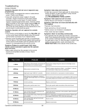
... to the control board to the gate controller. connections. 2 Blinks Safety sensors connected wrong Check for continued operation. If the LED blinks rapidly when pushing on reset Control board issue. Also, check for obstructions or excessive gate resistance. Check operation of the control box. When sensors are misaligned or blocked. Troubleshooting HAVING A PROBLEM? Adjust force setting (see PROGRAMMING FORCE LEARN). Operation and Maintenance 28 Check circuit breaker. • Issue with a volt meter. force (press PURPLE BUTTON 2 times then cycle...
... to the control board to the gate controller. connections. 2 Blinks Safety sensors connected wrong Check for continued operation. If the LED blinks rapidly when pushing on reset Control board issue. Also, check for obstructions or excessive gate resistance. Check operation of the control box. When sensors are misaligned or blocked. Troubleshooting HAVING A PROBLEM? Adjust force setting (see PROGRAMMING FORCE LEARN). Operation and Maintenance 28 Check circuit breaker. • Issue with a volt meter. force (press PURPLE BUTTON 2 times then cycle...
LA100 Linear Gate Operator Manual
Page 30
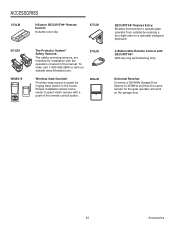
Universal Receiver Converts a 390 MHz Garage Door Opener to operate gate operator from outside by ringing base station in this manual. PRESS TO R ING 365LM SECURITY✚® Keyless Entry: Enables homeowner to 315MHz and thus the same remote for installation with the operators covered in the house. PRESS Simple installation allows home TO R ING owner to guest by entering a four digit code on the garage door. 30 PRESS PRESS TO...
Universal Receiver Converts a 390 MHz Garage Door Opener to operate gate operator from outside by ringing base station in this manual. PRESS TO R ING 365LM SECURITY✚® Keyless Entry: Enables homeowner to 315MHz and thus the same remote for installation with the operators covered in the house. PRESS Simple installation allows home TO R ING owner to guest by entering a four digit code on the garage door. 30 PRESS PRESS TO...
LA100 Linear Gate Operator Manual
Page 31
... SERVICE ORGANIZATION SPANS AMERICA FOR INSTALLATION AND SERVICE INFORMATION, CALL OUR TOLL FREE NUMBER 1-800-528-2806 www.liftmaster.com WHEN ORDERING REPAIR PARTS PLEASE SUPPLY THE FOLLOWING INFORMATION: PART NUMBER DESCRIPTION MODEL NUMBER ADDRESS ORDER TO: THE CHAMBERLAIN GROUP, INC. If, during the limited warranty period, this product appears to contain a defect covered by Seller are confirmed to you. ANY SERVICE CALL THAT DETERMINES THE PROBLEM...
... SERVICE ORGANIZATION SPANS AMERICA FOR INSTALLATION AND SERVICE INFORMATION, CALL OUR TOLL FREE NUMBER 1-800-528-2806 www.liftmaster.com WHEN ORDERING REPAIR PARTS PLEASE SUPPLY THE FOLLOWING INFORMATION: PART NUMBER DESCRIPTION MODEL NUMBER ADDRESS ORDER TO: THE CHAMBERLAIN GROUP, INC. If, during the limited warranty period, this product appears to contain a defect covered by Seller are confirmed to you. ANY SERVICE CALL THAT DETERMINES THE PROBLEM...


