GT- Logic 4 Installation Manual
Page 1
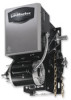
...are shipped in your area. The Logic 4 operator incorporates a self-diagnostic feature built into the (MAS) Maintenance Alert System LED. INSTALLATION MANUAL H, J, AND HJ T AND APT L 4 ogic L3 GH THIS PRODUCT IS TO BE INSTALLED AND SERVICED BY A TRAINED DOOR SYSTEMS TECHNICIAN ONLY. CONTACT INFORMATION GT 2 YEAR...RESIDENTIAL USE 315MHz Radio Receiver Built on the 3-button station will signal when the set an internal Maintenance Cycle Counter. Visit www.liftmaster.com to set number of cycles/months is reached or when the operator requires immediate service. An LED on Board
...are shipped in your area. The Logic 4 operator incorporates a self-diagnostic feature built into the (MAS) Maintenance Alert System LED. INSTALLATION MANUAL H, J, AND HJ T AND APT L 4 ogic L3 GH THIS PRODUCT IS TO BE INSTALLED AND SERVICED BY A TRAINED DOOR SYSTEMS TECHNICIAN ONLY. CONTACT INFORMATION GT 2 YEAR...RESIDENTIAL USE 315MHz Radio Receiver Built on the 3-button station will signal when the set an internal Maintenance Cycle Counter. Visit www.liftmaster.com to set number of cycles/months is reached or when the operator requires immediate service. An LED on Board

GT- Logic 4 Installation Manual
Page 2
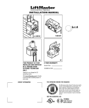
...Install the Manual Disconnect 17 WIRING 18-19 Power and Ground 18 Control Station 19 ENTRAPMENT PROTECTION 20-22 LiftMaster Monitored Entrapment Protection (LMEP 20 Install the Photoelectric Sensors (Provided 21 Mount the Photoelectric Sensors (Provided 22 Wire the...27 Emergency Disconnect System Model GT and T 26 Emergency Disconnect System Model APT 26 Emergency Disconnect System Model H, GH, J, and HJ 27 PROGRAMMING 28-35 Introduction to Order Repair Parts 36 TROUBLESHOOTING 37-40 Diagnostic Chart 37 Troubleshooting Guide 38 Troubleshooting Error Codes 39 ...
...Install the Manual Disconnect 17 WIRING 18-19 Power and Ground 18 Control Station 19 ENTRAPMENT PROTECTION 20-22 LiftMaster Monitored Entrapment Protection (LMEP 20 Install the Photoelectric Sensors (Provided 21 Mount the Photoelectric Sensors (Provided 22 Wire the...27 Emergency Disconnect System Model GT and T 26 Emergency Disconnect System Model APT 26 Emergency Disconnect System Model H, GH, J, and HJ 27 PROGRAMMING 28-35 Introduction to Order Repair Parts 36 TROUBLESHOOTING 37-40 Diagnostic Chart 37 Troubleshooting Guide 38 Troubleshooting Error Codes 39 ...

GT- Logic 4 Installation Manual
Page 13
... Model H and GH Floor level chain hoist with electrical interlock for manual door operation Model HJ Includes both floor level disconnect systems stated above ENTRAPMENT PROTECTION: LiftMaster Monitored Entrapment Protection (LMEP) Photoelectric Sensors (CPS-U Through beam used to 24 feet. LIMIT.... Safety Edge (Optional Electric or pneumatic sensing device attached to open and close with LED Hoist hand chain (Models H, HJ and GH ONLY) Door sprocket Door/operator drive chain Entrapment Protection Device: Model CPS-U photoelectric sensors (standard) OPERATOR SPECIFICATIONS MOTOR...
... Model H and GH Floor level chain hoist with electrical interlock for manual door operation Model HJ Includes both floor level disconnect systems stated above ENTRAPMENT PROTECTION: LiftMaster Monitored Entrapment Protection (LMEP) Photoelectric Sensors (CPS-U Through beam used to 24 feet. LIMIT.... Safety Edge (Optional Electric or pneumatic sensing device attached to open and close with LED Hoist hand chain (Models H, HJ and GH ONLY) Door sprocket Door/operator drive chain Entrapment Protection Device: Model CPS-U photoelectric sensors (standard) OPERATOR SPECIFICATIONS MOTOR...
GT- Logic 4 Installation Manual
Page 41
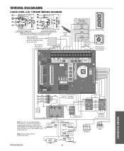
...DIAGRAMS WIRING DIAGRAMS LOGIC (VER. 4.0) 1 PHASE WIRING DIAGRAM 115V MOTOR CONNECTION 230V MOTOR CONNECTION NOTE: Gray (GY) and purple (PU) motor wires are reversed for LiftMaster Monitored Entrapment Protection (LMEP) device connections Hoist Interlock When Present TMR DEF (BL) SWITCH (YE) Sensing Edge Maintenance Alert LED (RD) (WH) Open Close Stop...BR) See Motor Connections (WH) 115 / 230 VOLT 1PH. White wires connect the COM on BYPASS L/S and LOCK SENSOR switch to page 26 for H and HJ right hand models and all GH and J models. Refer to NC on LOCK SENSOR switch.
...DIAGRAMS WIRING DIAGRAMS LOGIC (VER. 4.0) 1 PHASE WIRING DIAGRAM 115V MOTOR CONNECTION 230V MOTOR CONNECTION NOTE: Gray (GY) and purple (PU) motor wires are reversed for LiftMaster Monitored Entrapment Protection (LMEP) device connections Hoist Interlock When Present TMR DEF (BL) SWITCH (YE) Sensing Edge Maintenance Alert LED (RD) (WH) Open Close Stop...BR) See Motor Connections (WH) 115 / 230 VOLT 1PH. White wires connect the COM on BYPASS L/S and LOCK SENSOR switch to page 26 for H and HJ right hand models and all GH and J models. Refer to NC on LOCK SENSOR switch.
GT- Logic 4 Installation Manual
Page 42
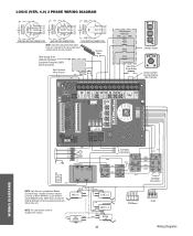
... Edge Refer to NC on LOCK SENSOR switch. White wires connect the COM on BYPASS L/S and Lock Sensor switch to page 26 for H and HJ right hand models and all GH and J models. LOGIC (VER. 4.0) 3 PHASE WIRING DIAGRAM 230V BRAKE (WHEN PRESENT) 230V BRAKE (WHEN PRESENT...YE) (BL/BK) 208/230V MOTOR CONNECTION 460V MOTOR CONNECTION 575V MOTOR CONNECTION NOTE: Gray (GY) and purple (PU) motor wires are reversed for LiftMaster Monitored Entrapment Protection (LMEP) device connections Hoist Interlock When Present TMR DEF (BL) SWITCH (YE) Maintenance Alert LED (RD) (WH) Open Close Stop...
... Edge Refer to NC on LOCK SENSOR switch. White wires connect the COM on BYPASS L/S and Lock Sensor switch to page 26 for H and HJ right hand models and all GH and J models. LOGIC (VER. 4.0) 3 PHASE WIRING DIAGRAM 230V BRAKE (WHEN PRESENT) 230V BRAKE (WHEN PRESENT...YE) (BL/BK) 208/230V MOTOR CONNECTION 460V MOTOR CONNECTION 575V MOTOR CONNECTION NOTE: Gray (GY) and purple (PU) motor wires are reversed for LiftMaster Monitored Entrapment Protection (LMEP) device connections Hoist Interlock When Present TMR DEF (BL) SWITCH (YE) Maintenance Alert LED (RD) (WH) Open Close Stop...
GT- Logic 4 User Manual
Page 1
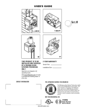
... C2 operating mode. The Logic 4 operator incorporates a self-diagnostic feature built into the (MAS) Maintenance Alert System LED. An LED on Board www.liftmaster.com Visit www.liftmaster.com to set number of cycles/months is reached or when the operator requires immediate service. USER'S GUIDE H, J, AND... HJ T AND APT L 4 ogic L3 L3 GH GT THIS PRODUCT IS TO BE INSTALLED AND SERVICED BY A TRAINED DOOR SYSTEMS TECHNICIAN ONLY. NOT FOR ...
... C2 operating mode. The Logic 4 operator incorporates a self-diagnostic feature built into the (MAS) Maintenance Alert System LED. An LED on Board www.liftmaster.com Visit www.liftmaster.com to set number of cycles/months is reached or when the operator requires immediate service. USER'S GUIDE H, J, AND... HJ T AND APT L 4 ogic L3 L3 GH GT THIS PRODUCT IS TO BE INSTALLED AND SERVICED BY A TRAINED DOOR SYSTEMS TECHNICIAN ONLY. NOT FOR ...
J- LOGIC 3 Manual
Page 1
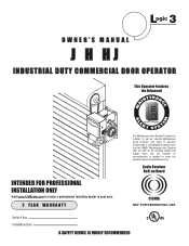
... incorporates a self-diagnostic feature built into the (MAS) Maintenance Alert System LED. L 3 ogic OWNER'S MANUAL J H HJ INDUSTRIAL DUTY COMMERCIAL DOOR OPERATOR This Operator Features the Enhanced INTENAN M A E M E C AL INTENDED FOR PROFESSIONAL INSTALLATION ONLY Visit www.LiftMaster.com to locate a professional installing dealer in your area. 2 YEAR WARRANTY E PATENT PENDING R T T SYS The Maintenance...
... incorporates a self-diagnostic feature built into the (MAS) Maintenance Alert System LED. L 3 ogic OWNER'S MANUAL J H HJ INDUSTRIAL DUTY COMMERCIAL DOOR OPERATOR This Operator Features the Enhanced INTENAN M A E M E C AL INTENDED FOR PROFESSIONAL INSTALLATION ONLY Visit www.LiftMaster.com to locate a professional installing dealer in your area. 2 YEAR WARRANTY E PATENT PENDING R T T SYS The Maintenance...
J Logic 4-Repair Parts Manual
Page 1
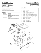
Replacement Parts Logic 4 Operators Models J, H, and HJ Individual Parts ITEM PART# DESCRIPTION 1 13-10024 Limit Nut 2 23-10041 Limit Switch 3 K75-35626 Cover 4 21-14182 Transformer, 115/230 Volts, 20Va 21-35057 ...-31229 Relay, 24 Vdc SPDT (C Relay) 1 Phase Only 7 K74-31243 MOV 580 Volts 8 K79-15016-1 RPM Sensor Assembly 9 K1A6837 Logic Board - 1-800-528-2806 www.liftmaster.com Electrical Box Electrical Box Replacement Kits To order a complete electrical box replacement kit, add a K-Prefix to the model number of your operator for example...
Replacement Parts Logic 4 Operators Models J, H, and HJ Individual Parts ITEM PART# DESCRIPTION 1 13-10024 Limit Nut 2 23-10041 Limit Switch 3 K75-35626 Cover 4 21-14182 Transformer, 115/230 Volts, 20Va 21-35057 ...-31229 Relay, 24 Vdc SPDT (C Relay) 1 Phase Only 7 K74-31243 MOV 580 Volts 8 K79-15016-1 RPM Sensor Assembly 9 K1A6837 Logic Board - 1-800-528-2806 www.liftmaster.com Electrical Box Electrical Box Replacement Kits To order a complete electrical box replacement kit, add a K-Prefix to the model number of your operator for example...
J VERSION 2 LOGIC Manual
Page 2
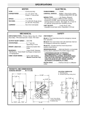
... BEARINGS Output Shaft: Shielded Ball Bearing. REVERSING EDGE:......(Optional) Electric or pneumatic sensing device attached to LiftMaster CPSII. A A 4.75" 2 Clutch Shaft: IronCopper sintered and oil impregnated. HAND CHAIN WHEEL: .........Left or right handing Models H and HJ only. PHOTO EYES Interface directly to the bottom edge of door. WEIGHTS AND DIMENSIONS HANGING WEIGHT...
... BEARINGS Output Shaft: Shielded Ball Bearing. REVERSING EDGE:......(Optional) Electric or pneumatic sensing device attached to LiftMaster CPSII. A A 4.75" 2 Clutch Shaft: IronCopper sintered and oil impregnated. HAND CHAIN WHEEL: .........Left or right handing Models H and HJ only. PHOTO EYES Interface directly to the bottom edge of door. WEIGHTS AND DIMENSIONS HANGING WEIGHT...


