
GT- Logic 4 Installation Manual
Page 2
...4-5 Maximum Door Area 5 Weights and Dimensions 6 ASSEMBLY 7-9 Assemble the Operator (Models T and GT 7 Install the Chain (Models T and GT 8 Assemble the Operator (Model APT 9 TYPICAL INSTALLATION 10-12 Install the Header Bracket 10 Attach the Track to...LiftMaster Monitored Entrapment Protection (LMEP) Devices 22 ADJUSTMENT 23-24 Limit Adjustment 23 Clutch Adjustment (Belt Drive Model Operators 24 TESTING 25 MANUAL RELEASE 26-27 Emergency Disconnect System Model GT and T 26 Emergency Disconnect System Model APT 26 Emergency Disconnect System Model H, GH, J, and HJ...
...4-5 Maximum Door Area 5 Weights and Dimensions 6 ASSEMBLY 7-9 Assemble the Operator (Models T and GT 7 Install the Chain (Models T and GT 8 Assemble the Operator (Model APT 9 TYPICAL INSTALLATION 10-12 Install the Header Bracket 10 Attach the Track to...LiftMaster Monitored Entrapment Protection (LMEP) Devices 22 ADJUSTMENT 23-24 Limit Adjustment 23 Clutch Adjustment (Belt Drive Model Operators 24 TESTING 25 MANUAL RELEASE 26-27 Emergency Disconnect System Model GT and T 26 Emergency Disconnect System Model APT 26 Emergency Disconnect System Model H, GH, J, and HJ...

GT- Logic 4 Installation Manual
Page 4
... ADJUST Linear driven, fully adjustable screw type cams. Adjustable to provide non-contact safety protection. ENTRAPMENT PROTECTION: LiftMaster Monitored Entrapment Protection (LMEP) Photoelectric Sensors (CPS-U Through beam used to 24 feet. Safety Edge (Optional ...sensing device attached to open override. Trolley 4 TROLLEY TROLLEY OPERATORS CARTON INVENTORY Before beginning your installation check that all GT models) Entrapment Protection Device: Model CPS-U photoelectric sensors (standard) NOTE: The tracks are shipped separately. See page 29 for emergency manual door operation....
... ADJUST Linear driven, fully adjustable screw type cams. Adjustable to provide non-contact safety protection. ENTRAPMENT PROTECTION: LiftMaster Monitored Entrapment Protection (LMEP) Photoelectric Sensors (CPS-U Through beam used to 24 feet. Safety Edge (Optional ...sensing device attached to open override. Trolley 4 TROLLEY TROLLEY OPERATORS CARTON INVENTORY Before beginning your installation check that all GT models) Entrapment Protection Device: Model CPS-U photoelectric sensors (standard) NOTE: The tracks are shipped separately. See page 29 for emergency manual door operation....
GT- Logic 4 Installation Manual
Page 5
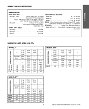
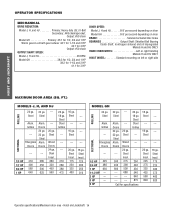
... Heavy duty worm gear-in-oil-bath speed reducer Output: #41 chain OUTPUT SHAFT SPEED: Model APT 96 RPM Model GT 113.5 RPM Model T 140 RPM DOOR SPEED (not adjustable): Model APT 6-7" per second Model GT 11-12" per second Model T 11-12" per second BRAKE: Solenoid actuated disc brake on 3/4 and 1 HP, standard... 1/2 HP 250 20 ga. Steel Wood Doors 24 ga. Steel Insul. 125 200 275 310 STANDARD SECTIONAL MODEL APT 24 ga. 22 ga. Steel --- 20 ga. Steel Insul. 100 STANDARD SECTIONAL MODEL GT --- Trolley Steel Alum. Steel Insul. 320 450 500 550 16 ga. Steel Insul. 225 16 ga...
... Heavy duty worm gear-in-oil-bath speed reducer Output: #41 chain OUTPUT SHAFT SPEED: Model APT 96 RPM Model GT 113.5 RPM Model T 140 RPM DOOR SPEED (not adjustable): Model APT 6-7" per second Model GT 11-12" per second Model T 11-12" per second BRAKE: Solenoid actuated disc brake on 3/4 and 1 HP, standard... 1/2 HP 250 20 ga. Steel Wood Doors 24 ga. Steel Insul. 125 200 275 310 STANDARD SECTIONAL MODEL APT 24 ga. 22 ga. Steel --- 20 ga. Steel Insul. 100 STANDARD SECTIONAL MODEL GT --- Trolley Steel Alum. Steel Insul. 320 450 500 550 16 ga. Steel Insul. 225 16 ga...
GT- Logic 4 Installation Manual
Page 6
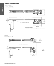
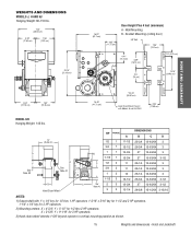
For Units with Brake add 3-1/2" (Standard on T 1/3 and 1/2 HP models) MODEL GT Hanging Weight: 140 lbs. 4" (10.16 cm) Door Height Plus 4 feet (minimum) 13.05" (33.15 cm) * 17.5" (44.45 cm) 18.5" (46.99 cm) Weights and dimensions - Trolley 6 Optional on APT, T 3/4 and T 1 HP models; TROLLEY WEIGHTS AND DIMENSIONS MODELS T AND APT Hanging Weight: 80-110 lbs. 4" (10.16 cm) 14" (35.56 cm) *Door Height Plus 4 feet (minimum) Highest Point of Door Travel 11.63" (29.54 cm) *23.43" (59.51 cm) *-
For Units with Brake add 3-1/2" (Standard on T 1/3 and 1/2 HP models) MODEL GT Hanging Weight: 140 lbs. 4" (10.16 cm) Door Height Plus 4 feet (minimum) 13.05" (33.15 cm) * 17.5" (44.45 cm) 18.5" (46.99 cm) Weights and dimensions - Trolley 6 Optional on APT, T 3/4 and T 1 HP models; TROLLEY WEIGHTS AND DIMENSIONS MODELS T AND APT Hanging Weight: 80-110 lbs. 4" (10.16 cm) 14" (35.56 cm) *Door Height Plus 4 feet (minimum) Highest Point of Door Travel 11.63" (29.54 cm) *23.43" (59.51 cm) *-
GT- Logic 4 Installation Manual
Page 7
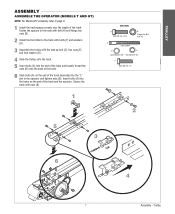
... (B). 1 HARDWARE A Bolt 3/8"-16 x 3/4" B Flange Hex Nut 3/8"-16 C Take Up Bolt D E Lock Washer 3/8" Hex Nut 3/8"-16 F Bolt 3/8"-16 x 1" 2 5 3 6 4 7 Assembly - TROLLEY ASSEMBLY ASSEMBLE THE OPERATOR (MODELS T AND GT) NOTE: For Model APT assembly refer to the track with bolts (F) and washers (D). 3 Assemble the trolley with the take up bolt (C), hex nuts (E), and lock washer...
... (B). 1 HARDWARE A Bolt 3/8"-16 x 3/4" B Flange Hex Nut 3/8"-16 C Take Up Bolt D E Lock Washer 3/8" Hex Nut 3/8"-16 F Bolt 3/8"-16 x 1" 2 5 3 6 4 7 Assembly - TROLLEY ASSEMBLY ASSEMBLE THE OPERATOR (MODELS T AND GT) NOTE: For Model APT assembly refer to the track with bolts (F) and washers (D). 3 Assemble the trolley with the take up bolt (C), hex nuts (E), and lock washer...
GT- Logic 4 Installation Manual
Page 8
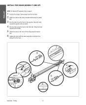
... the operator. Wrap the chain around the front idler. 5 Attach the chain to the front of the track. 2 1 2˝ MODEL T 3 MODEL GT 4 5 6 3˝ Assembly - Trolley 8 TROLLEY INSTALL THE CHAIN (MODELS T AND GT) NOTE: For Model APT assembly refer to page 9. 1 Position the trolley 2 inches away from the front idler. 2 Attach the chain to the...
... the operator. Wrap the chain around the front idler. 5 Attach the chain to the front of the track. 2 1 2˝ MODEL T 3 MODEL GT 4 5 6 3˝ Assembly - Trolley 8 TROLLEY INSTALL THE CHAIN (MODELS T AND GT) NOTE: For Model APT assembly refer to page 9. 1 Position the trolley 2 inches away from the front idler. 2 Attach the chain to the...
GT- Logic 4 Installation Manual
Page 9
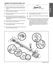
... the "L" slot in the trolley. 4 Insert bolts (A) into the holes on the end of the track and the operator. TROLLEY ASSEMBLE THE OPERATOR (MODEL APT) NOTE: If your model is no binding. 7 Run the chain along the track to the front idler. Slide the trolley back and forth past the drive chain...
... the "L" slot in the trolley. 4 Insert bolts (A) into the holes on the end of the track and the operator. TROLLEY ASSEMBLE THE OPERATOR (MODEL APT) NOTE: If your model is no binding. 7 Run the chain along the track to the front idler. Slide the trolley back and forth past the drive chain...

GT- Logic 4 Installation Manual
Page 13
... Electric or pneumatic sensing device attached to open and close with open override. See page 29 for manual door operation Model HJ Includes both floor level disconnect systems stated above ENTRAPMENT PROTECTION: LiftMaster Monitored Entrapment Protection (LMEP) Photoelectric Sensors (CPS-U Through beam used to 24 feet. LIMIT ADJUST Linear driven, fully adjustable screw...
... Electric or pneumatic sensing device attached to open and close with open override. See page 29 for manual door operation Model HJ Includes both floor level disconnect systems stated above ENTRAPMENT PROTECTION: LiftMaster Monitored Entrapment Protection (LMEP) Photoelectric Sensors (CPS-U Through beam used to 24 feet. LIMIT ADJUST Linear driven, fully adjustable screw...
GT- Logic 4 Installation Manual
Page 14
... 210 280 380 475 16 ga. Steel Alum. Steel --- 20 ga. Fiberglass Doors Alum. Steel --- --- --- 16 ga. --Steel --- --- 20 ga. Grilles --- FT.) MODELS J, H, AND HJ 24 ga. 22 ga. Doors SECTIONAL --- --- 1/3 HP 310 285 1/2 HP 400 350 3/4 HP 560 500 1 HP 640 625 --- --- 20 ga. Steel Insul. 260 ... and 1 HP Worm gear-in-oil bath gear reducer 44:1 for 1-1/2 and 2 HP 42:1 for 3 HP Output: #50 chain OUTPUT SHAFT SPEED: Model J, H and HJ 36 RPM Model GH 38.3 for 1/2, 3/4 and 1 HP 39.2 for 1-1/2 and 2 HP 41.1 for specifications 16 ga. Steel Insul. 275 390 500 680 -----...
... 210 280 380 475 16 ga. Steel Alum. Steel --- 20 ga. Fiberglass Doors Alum. Steel --- --- --- 16 ga. --Steel --- --- 20 ga. Grilles --- FT.) MODELS J, H, AND HJ 24 ga. 22 ga. Doors SECTIONAL --- --- 1/3 HP 310 285 1/2 HP 400 350 3/4 HP 560 500 1 HP 640 625 --- --- 20 ga. Steel Insul. 260 ... and 1 HP Worm gear-in-oil bath gear reducer 44:1 for 1-1/2 and 2 HP 42:1 for 3 HP Output: #50 chain OUTPUT SHAFT SPEED: Model J, H and HJ 36 RPM Model GH 38.3 for 1/2, 3/4 and 1 HP 39.2 for 1-1/2 and 2 HP 41.1 for specifications 16 ga. Steel Insul. 275 390 500 680 -----...
GT- Logic 4 Installation Manual
Page 15
.... Hoist and Jackshaft Y = 5-1/2" for 3 HP operators. 3) Hand chain wheel extends 1-5/8" beyond operator in vertical mounting position as shown. 15 Weights and dimensions - WEIGHTS AND DIMENSIONS MODELS J, H AND HJ Hanging Weight: 80-110 lbs. 14.5" (36.83 cm) 6.94" (17.63 cm) 7.56" (19.2 cm) 20.15" (51.18 cm) 8.34" (21.18...-1/4 12-63/64 3 26-1/4 12-63/64 3 26-3/4 13-63/64 3-1/2 27 13-63/64 3-1/2 28-5/8 15-15/64 3-15/16 NOTES: 1) Output shaft with Models H and HJ ONLY 4.56" (11.58 cm) HOIST AND JACKSHAFT...
.... Hoist and Jackshaft Y = 5-1/2" for 3 HP operators. 3) Hand chain wheel extends 1-5/8" beyond operator in vertical mounting position as shown. 15 Weights and dimensions - WEIGHTS AND DIMENSIONS MODELS J, H AND HJ Hanging Weight: 80-110 lbs. 14.5" (36.83 cm) 6.94" (17.63 cm) 7.56" (19.2 cm) 20.15" (51.18 cm) 8.34" (21.18...-1/4 12-63/64 3 26-1/4 12-63/64 3 26-3/4 13-63/64 3-1/2 27 13-63/64 3-1/2 28-5/8 15-15/64 3-15/16 NOTES: 1) Output shaft with Models H and HJ ONLY 4.56" (11.58 cm) HOIST AND JACKSHAFT...

GT- Logic 4 Installation Manual
Page 16
...a. Be rigid to prevent play between PRECAUCIÓN the door shaft and operator drive shaft is out of balance. c. AVERTISSEMENT For models H and HJ with the drive shaft parallel to remain functional, install an interlock switch. • ALWAYS call a trained door systems technician if door...DEATDERVMEINRETMEOUNNCTIIANG LOCATION 1 The operator may NOT reverse when required. • NEVER try to structural supports of the door jamb. On models J, H, HJ and GH operators the drive sprocket can cause SERIOUS PERSONAL INJURY. • Disable ALL locks and remove ALL ropes connected to ...
...a. Be rigid to prevent play between PRECAUCIÓN the door shaft and operator drive shaft is out of balance. c. AVERTISSEMENT For models H and HJ with the drive shaft parallel to remain functional, install an interlock switch. • ALWAYS call a trained door systems technician if door...DEATDERVMEINRETMEOUNNCTIIANG LOCATION 1 The operator may NOT reverse when required. • NEVER try to structural supports of the door jamb. On models J, H, HJ and GH operators the drive sprocket can cause SERIOUS PERSONAL INJURY. • Disable ALL locks and remove ALL ropes connected to ...
GT- Logic 4 Installation Manual
Page 20
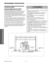
... 20 P6"h(o1to5SSeaecfnleemstcoy)trrRmicevaSexre.sniansbgoorve floor ADVERTENCIA ADVERTENCIA - above the floor. The operator comes standard with the photoelectric sensors model CPS-U, additional entrapment devices are for most wiring types (refer to the full open position. WARNING To prevent possible SERIOUS...connected and aligned. For D1, C2, and E2 wiring AVERTISSEMENT the installation of an entrapment device is recommended. • LiftMaster Monitored Entrapment Protection devices are available for B2, TS, T, and FSTS wiring types and MUST NOT be installed facing ...
... 20 P6"h(o1to5SSeaecfnleemstcoy)trrRmicevaSexre.sniansbgoorve floor ADVERTENCIA ADVERTENCIA - above the floor. The operator comes standard with the photoelectric sensors model CPS-U, additional entrapment devices are for most wiring types (refer to the full open position. WARNING To prevent possible SERIOUS...connected and aligned. For D1, C2, and E2 wiring AVERTISSEMENT the installation of an entrapment device is recommended. • LiftMaster Monitored Entrapment Protection devices are available for B2, TS, T, and FSTS wiring types and MUST NOT be installed facing ...
GT- Logic 4 Installation Manual
Page 22
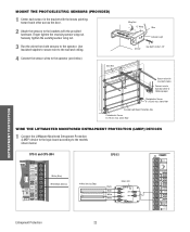
Use insulated staples to secure wire to the wall and ceiling. 4 Connect the sensor wires to the models shown below ). above floor WIRE THE LIFTMASTER MONITORED ENTRAPMENT PROTECTION (LMEP) DEVICES 1 Connect the LiftMaster Monitored Entrapment Protection (LMEP) device to the logic board according to the operator (see below : CPS-U and CPS-UN4 CPS...
Use insulated staples to secure wire to the wall and ceiling. 4 Connect the sensor wires to the models shown below ). above floor WIRE THE LIFTMASTER MONITORED ENTRAPMENT PROTECTION (LMEP) DEVICES 1 Connect the LiftMaster Monitored Entrapment Protection (LMEP) device to the logic board according to the operator (see below : CPS-U and CPS-UN4 CPS...
GT- Logic 4 Installation Manual
Page 24
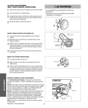
... cotter pin from electrocution: • Disconnect electric power BEFORE performing ANY adjustments or maintenance. 12 4 AV3ERTISSEMENT ATTENTION ADJUST TORQUE LIMITER CLUTCH (MODEL GT) 1 Loosen set screw that is directly over the flat portion of the door and to allow PRECAUCIÓN the clutch to .... 2 Back off clutch nut until there is automatically learned and does not require programming. AVERTISSEMENT Torque Nut Set Screws MODEL GH (OPTIONAL MODIFICATION) 1 Loosen set screws on the 2 ADVERTENCIA clutch spring. 3 Tighten clutch nut gradually until there is very little...
... cotter pin from electrocution: • Disconnect electric power BEFORE performing ANY adjustments or maintenance. 12 4 AV3ERTISSEMENT ATTENTION ADJUST TORQUE LIMITER CLUTCH (MODEL GT) 1 Loosen set screw that is directly over the flat portion of the door and to allow PRECAUCIÓN the clutch to .... 2 Back off clutch nut until there is automatically learned and does not require programming. AVERTISSEMENT Torque Nut Set Screws MODEL GH (OPTIONAL MODIFICATION) 1 Loosen set screws on the 2 ADVERTENCIA clutch spring. 3 Tighten clutch nut gradually until there is very little...
GT- Logic 4 Installation Manual
Page 26
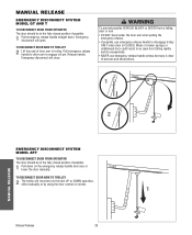
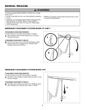
... RECONNECT DOOR ARM TO TROLLEY 2 Lift free end of persons and obstructions. 1 AVERTISSEMENT ATTENTION 2 NOTICE MANUAL RELEASE EMERGENCY DISCONNECT SYSTEM MODEL APT TO DISCONNECT DOOR FROM OPERATOR The door should be in the fully closed position if possible. 1 Pull emergency release handle straight down...arm when pulling the emergency release. • If possible, use emergency release handle unless doorway is CLOSED. MANUAL RELEASE EMERGENCY DISCONNECT SYSTEM MODEL GT AND T TO DISCONNECT DOOR FROM OPERATOR The door should be in the fully closed position if possible. 1 Pull down . TO...
... RECONNECT DOOR ARM TO TROLLEY 2 Lift free end of persons and obstructions. 1 AVERTISSEMENT ATTENTION 2 NOTICE MANUAL RELEASE EMERGENCY DISCONNECT SYSTEM MODEL APT TO DISCONNECT DOOR FROM OPERATOR The door should be in the fully closed position if possible. 1 Pull emergency release handle straight down...arm when pulling the emergency release. • If possible, use emergency release handle unless doorway is CLOSED. MANUAL RELEASE EMERGENCY DISCONNECT SYSTEM MODEL GT AND T TO DISCONNECT DOOR FROM OPERATOR The door should be in the fully closed position if possible. 1 Pull down . TO...
GT- Logic 4 Installation Manual
Page 27
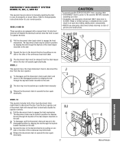
...pulled down manually. 3 Release the disconnect chain to operate the door again electrically. 2 J 3 1 1 2 ADVERTENCIA PRECAUCIÓN MANUAL RELEASE MODEL HJ This operator includes both a floor level disconnect chain (sash chain) to disconnect the door from a moving chain: • DISCONNECT electric ...power to engage the hoist mechanism. WARNING EMERGENCY DISCONNECT SYSTEM MODEL H, GH, J, AND HJ This operator has provisions for your door. • If possible, use emergency disconnect unless doorway is CLOSED. Weak ...
...pulled down manually. 3 Release the disconnect chain to operate the door again electrically. 2 J 3 1 1 2 ADVERTENCIA PRECAUCIÓN MANUAL RELEASE MODEL HJ This operator includes both a floor level disconnect chain (sash chain) to disconnect the door from a moving chain: • DISCONNECT electric ...power to engage the hoist mechanism. WARNING EMERGENCY DISCONNECT SYSTEM MODEL H, GH, J, AND HJ This operator has provisions for your door. • If possible, use emergency disconnect unless doorway is CLOSED. Weak ...

GT- Logic 4 Installation Manual
Page 36
... or silicone spray). • Do not lubricate motor. Fasteners Check and tighten as required. Call our TOLL FREE number: 1-800-528-2806 www.liftmaster.com LIFAEDOVFEORPETREATNOCRIFAEATURE (ODOMETER/CYCLE COUNATEDR)VERTENCIA The operator is observed or suspected. OPEN for every 5,000 cycles and CLOSE for wear and lubricate. Inspect the... to the desired wiring type. BeAlt TTENTION Check condition and tension. Check at the factory and should not need additional adjustment for some models. The open and close lights will be performed by a trained door systems technician.
... or silicone spray). • Do not lubricate motor. Fasteners Check and tighten as required. Call our TOLL FREE number: 1-800-528-2806 www.liftmaster.com LIFAEDOVFEORPETREATNOCRIFAEATURE (ODOMETER/CYCLE COUNATEDR)VERTENCIA The operator is observed or suspected. OPEN for every 5,000 cycles and CLOSE for wear and lubricate. Inspect the... to the desired wiring type. BeAlt TTENTION Check condition and tension. Check at the factory and should not need additional adjustment for some models. The open and close lights will be performed by a trained door systems technician.
GT- Logic 4 Installation Manual
Page 41
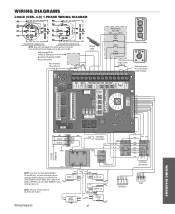
... COM OPEN L/S NO NC (WH) COM NO CLOSE L/S NC (YE) NOTE: The Lock Sensor switch is provided on Models DJ and DH only, red wire from main harness connects to NC on Bypass L/S and to NC on LOCK SENSOR switch.... WIRING DIAGRAM 115V MOTOR CONNECTION 230V MOTOR CONNECTION NOTE: Gray (GY) and purple (PU) motor wires are reversed for LiftMaster Monitored Entrapment Protection (LMEP) device connections Hoist Interlock When Present TMR DEF (BL) SWITCH (YE) Sensing Edge Maintenance Alert... Connections (WH) 115 / 230 VOLT 1PH. Refer to page 26 for H and HJ right hand models and all GH and...
... COM OPEN L/S NO NC (WH) COM NO CLOSE L/S NC (YE) NOTE: The Lock Sensor switch is provided on Models DJ and DH only, red wire from main harness connects to NC on Bypass L/S and to NC on LOCK SENSOR switch.... WIRING DIAGRAM 115V MOTOR CONNECTION 230V MOTOR CONNECTION NOTE: Gray (GY) and purple (PU) motor wires are reversed for LiftMaster Monitored Entrapment Protection (LMEP) device connections Hoist Interlock When Present TMR DEF (BL) SWITCH (YE) Sensing Edge Maintenance Alert... Connections (WH) 115 / 230 VOLT 1PH. Refer to page 26 for H and HJ right hand models and all GH and...
GT- Logic 4 Installation Manual
Page 42
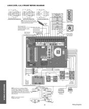
Sensing Edge Refer to page 26 for H and HJ right hand models and all GH and J models. POWER IN NOTE: Lock Sensor is located in the chassis. (WH) LOCK (RD) NO SENSOR (see note at left) NC (WH) NC SAFETY L/S NO COM (... (BR) 3 (YE) (BL/BK) 208/230V MOTOR CONNECTION 460V MOTOR CONNECTION 575V MOTOR CONNECTION NOTE: Gray (GY) and purple (PU) motor wires are reversed for LiftMaster Monitored Entrapment Protection (LMEP) device connections Hoist Interlock When Present TMR DEF (BL) SWITCH (YE) Maintenance Alert LED (RD) (WH) Open Close Stop OPEN CLOSE...
Sensing Edge Refer to page 26 for H and HJ right hand models and all GH and J models. POWER IN NOTE: Lock Sensor is located in the chassis. (WH) LOCK (RD) NO SENSOR (see note at left) NC (WH) NC SAFETY L/S NO COM (... (BR) 3 (YE) (BL/BK) 208/230V MOTOR CONNECTION 460V MOTOR CONNECTION 575V MOTOR CONNECTION NOTE: Gray (GY) and purple (PU) motor wires are reversed for LiftMaster Monitored Entrapment Protection (LMEP) device connections Hoist Interlock When Present TMR DEF (BL) SWITCH (YE) Maintenance Alert LED (RD) (WH) Open Close Stop OPEN CLOSE...
GT- Logic 4 User Manual
Page 6
...next UP or DOWN operation, either manually or by using the door control or remote. 1 N O T I C E 6 AD A EMERGENCY DISCONNECT SYSTEM MODEL GT AND T TO DISCONNECT DOOR FROM OPERATOR The door should be in an open . 1 TO RECONNECT DOOR ARM TO TROLLEY ATTENTION 2 Lift free end of... reconnect on the emergency release handle and raise or lower the door manually. Release handle. AVE AV 2 NOTICE EMERGENCY DISCONNECT SYSTEM MODEL APT TO DISCONNECT DOOR FROM OPERATOR ADVERTENCIA The door should be in the fully closed position if possible. Emergency disconnect will open door...
...next UP or DOWN operation, either manually or by using the door control or remote. 1 N O T I C E 6 AD A EMERGENCY DISCONNECT SYSTEM MODEL GT AND T TO DISCONNECT DOOR FROM OPERATOR The door should be in an open . 1 TO RECONNECT DOOR ARM TO TROLLEY ATTENTION 2 Lift free end of... reconnect on the emergency release handle and raise or lower the door manually. Release handle. AVE AV 2 NOTICE EMERGENCY DISCONNECT SYSTEM MODEL APT TO DISCONNECT DOOR FROM OPERATOR ADVERTENCIA The door should be in the fully closed position if possible. Emergency disconnect will open door...


