

GT- Logic 4 Installation Manual
Page 2
... 4-5 Maximum Door Area 5 Weights and Dimensions 6 ASSEMBLY 7-9 Assemble the Operator (Models T and GT 7 Install the Chain (Models T and GT 8 Assemble the Operator (Model APT 9 TYPICAL INSTALLATION 10-12 Install the Header Bracket 10 Attach the Track to...LiftMaster Monitored Entrapment Protection (LMEP) Devices 22 ADJUSTMENT 23-24 Limit Adjustment 23 Clutch Adjustment (Belt Drive Model Operators 24 TESTING 25 MANUAL RELEASE 26-27 Emergency Disconnect System Model GT and T 26 Emergency Disconnect System Model APT 26 Emergency Disconnect System Model H, GH...
... 4-5 Maximum Door Area 5 Weights and Dimensions 6 ASSEMBLY 7-9 Assemble the Operator (Models T and GT 7 Install the Chain (Models T and GT 8 Assemble the Operator (Model APT 9 TYPICAL INSTALLATION 10-12 Install the Header Bracket 10 Attach the Track to...LiftMaster Monitored Entrapment Protection (LMEP) Devices 22 ADJUSTMENT 23-24 Limit Adjustment 23 Clutch Adjustment (Belt Drive Model Operators 24 TESTING 25 MANUAL RELEASE 26-27 Emergency Disconnect System Model GT and T 26 Emergency Disconnect System Model APT 26 Emergency Disconnect System Model H, GH...

GT- Logic 4 Installation Manual
Page 4
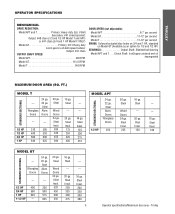
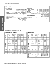
...override. SAFETY DISCONNECT Quick disconnect door arm for 3/4 HP and higher (all components were provided. ENTRAPMENT PROTECTION: LiftMaster Monitored Entrapment Protection (LMEP) Photoelectric Sensors (CPS-U Through beam used to 24 feet. TROLLEY TROLLEY OPERATORS CARTON... 5.6 6.8 8 10 208/230-3Ø, 60Hz 3 3.1 4 6 7 460-3Ø, 60Hz 1.5 1.75 2 3 3.5 575-3Ø, 60Hz 1.3 1.4 1.6 1.8 2.75 Model APT Voltage-Phase 115-1Ø, 60Hz 1/2 HP 11.2 ELECTRICAL TRANSFORMER 24Vac Secondary CONTROL STATION NEMA 3-Button Station Open/Close/Stop w/LED WIRING TYPE C2 (Standard...
...override. SAFETY DISCONNECT Quick disconnect door arm for 3/4 HP and higher (all components were provided. ENTRAPMENT PROTECTION: LiftMaster Monitored Entrapment Protection (LMEP) Photoelectric Sensors (CPS-U Through beam used to 24 feet. TROLLEY TROLLEY OPERATORS CARTON... 5.6 6.8 8 10 208/230-3Ø, 60Hz 3 3.1 4 6 7 460-3Ø, 60Hz 1.5 1.75 2 3 3.5 575-3Ø, 60Hz 1.3 1.4 1.6 1.8 2.75 Model APT Voltage-Phase 115-1Ø, 60Hz 1/2 HP 11.2 ELECTRICAL TRANSFORMER 24Vac Secondary CONTROL STATION NEMA 3-Button Station Open/Close/Stop w/LED WIRING TYPE C2 (Standard...
GT- Logic 4 Installation Manual
Page 5
...HP 400 350 3/4 HP 560 500 1 HP 640 625 20 ga. Steel Insul. 175 250 325 400 --- --- 16 ga. Steel Insul. 100 STANDARD SECTIONAL MODEL GT --- Steel Wood Doors 24 ga. Fiberglass Doors 24 ga. 22 ga. Steel Insul. 225 16 ga. Fiberglass Doors 24 ga. 22 ga. Steel ---... Insul. 260 320 450 560 16 ga. Steel Alum. Steel Insul. 250 325 400 475 --- --- 16 ga. Trolley TROLLEY OPERATOR SPECIFICATIONS MECHANICAL DRIVE REDUCTION: Model APT and T Primary: Heavy duty (5L) V-Belt Secondary: #41 chain/sprocket; Steel Insul. 150 --- --- 16 ga. Steel Insul. 320 450 500 550 16...
...HP 400 350 3/4 HP 560 500 1 HP 640 625 20 ga. Steel Insul. 175 250 325 400 --- --- 16 ga. Steel Insul. 100 STANDARD SECTIONAL MODEL GT --- Steel Wood Doors 24 ga. Fiberglass Doors 24 ga. 22 ga. Steel Insul. 225 16 ga. Fiberglass Doors 24 ga. 22 ga. Steel ---... Insul. 260 320 450 560 16 ga. Steel Alum. Steel Insul. 250 325 400 475 --- --- 16 ga. Trolley TROLLEY OPERATOR SPECIFICATIONS MECHANICAL DRIVE REDUCTION: Model APT and T Primary: Heavy duty (5L) V-Belt Secondary: #41 chain/sprocket; Steel Insul. 150 --- --- 16 ga. Steel Insul. 320 450 500 550 16...
GT- Logic 4 Installation Manual
Page 6
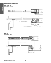
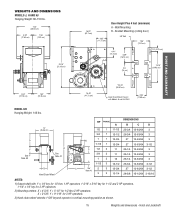
Optional on APT, T 3/4 and T 1 HP models; Trolley 6 For Units with Brake add 3-1/2" (Standard on T 1/3 and 1/2 HP models) MODEL GT Hanging Weight: 140 lbs. 4" (10.16 cm) Door Height Plus 4 feet (minimum) 13.05" (33.15 cm) * 17.5" (44.45 cm) 18.5" (46.99 cm) Weights and dimensions - TROLLEY WEIGHTS AND DIMENSIONS MODELS T AND APT Hanging Weight: 80-110 lbs. 4" (10.16 cm) 14" (35.56 cm) *Door Height Plus 4 feet (minimum) Highest Point of Door Travel 11.63" (29.54 cm) *23.43" (59.51 cm) *-
Optional on APT, T 3/4 and T 1 HP models; Trolley 6 For Units with Brake add 3-1/2" (Standard on T 1/3 and 1/2 HP models) MODEL GT Hanging Weight: 140 lbs. 4" (10.16 cm) Door Height Plus 4 feet (minimum) 13.05" (33.15 cm) * 17.5" (44.45 cm) 18.5" (46.99 cm) Weights and dimensions - TROLLEY WEIGHTS AND DIMENSIONS MODELS T AND APT Hanging Weight: 80-110 lbs. 4" (10.16 cm) 14" (35.56 cm) *Door Height Plus 4 feet (minimum) Highest Point of Door Travel 11.63" (29.54 cm) *23.43" (59.51 cm) *-
GT- Logic 4 Installation Manual
Page 7
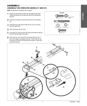
... front idler to page 9. 1 Install the track spacers evenly over the length of the track and the operator. TROLLEY ASSEMBLY ASSEMBLE THE OPERATOR (MODELS T AND GT) NOTE: For Model APT assembly refer to the track with bolts (F) and washers (D). 3 Assemble the trolley with nuts (B). 1 HARDWARE A Bolt 3/8"-16 x 3/4" B Flange Hex Nut 3/8"-16 C Take...
... front idler to page 9. 1 Install the track spacers evenly over the length of the track and the operator. TROLLEY ASSEMBLY ASSEMBLE THE OPERATOR (MODELS T AND GT) NOTE: For Model APT assembly refer to the track with bolts (F) and washers (D). 3 Assemble the trolley with nuts (B). 1 HARDWARE A Bolt 3/8"-16 x 3/4" B Flange Hex Nut 3/8"-16 C Take...
GT- Logic 4 Installation Manual
Page 8
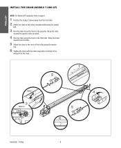
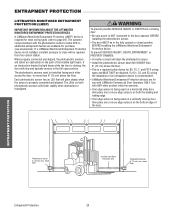
Wrap the chain around the front idler. 5 Attach the chain to the front of the track. 2 1 2˝ MODEL T 3 MODEL GT 4 5 6 3˝ Assembly - TROLLEY INSTALL THE CHAIN (MODELS T AND GT) NOTE: For Model APT assembly refer to page 9. 1 Position the trolley 2 inches away from the front idler. 2 Attach the chain to the trolley threaded shaft using...
Wrap the chain around the front idler. 5 Attach the chain to the front of the track. 2 1 2˝ MODEL T 3 MODEL GT 4 5 6 3˝ Assembly - TROLLEY INSTALL THE CHAIN (MODELS T AND GT) NOTE: For Model APT assembly refer to page 9. 1 Position the trolley 2 inches away from the front idler. 2 Attach the chain to the trolley threaded shaft using...
GT- Logic 4 Installation Manual
Page 9
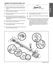
... need to be loosened or tightened to adjust the slack of the bolts. Slide bolts (A) on the end of the track. TROLLEY ASSEMBLE THE OPERATOR (MODEL APT) NOTE: If your model is no binding. 7 Run the chain along the track to the front idler.
... need to be loosened or tightened to adjust the slack of the bolts. Slide bolts (A) on the end of the track. TROLLEY ASSEMBLE THE OPERATOR (MODEL APT) NOTE: If your model is no binding. 7 Run the chain along the track to the front idler.

GT- Logic 4 Installation Manual
Page 13
... protection. Hoist and Jackshaft See page 29 for manual door operation Model HJ Includes both floor level disconnect systems stated above ENTRAPMENT PROTECTION: LiftMaster Monitored Entrapment Protection (LMEP) Photoelectric Sensors (CPS-U Through beam used... 60Hz 8.5 11.2 13.6 16 230-1Ø, 60Hz 4.2 5.6 6.8 8 208/230-3Ø, 60Hz 3 3.1 4 6 460-3Ø, 60Hz 1.5 1.75 2 3 575-3Ø, 60Hz 1.3 1.4 1.6 1.8 Model GH Voltage-Phase 1/2 HP 3/4 HP 1 HP 1-1/2 HP 2 HP 3 HP 115-1Ø, 60Hz 11.2 13.6 16 20 - - 230-1Ø, 60Hz 5.6 6.8 8 10 - - 208/230-3Ø, ...
... protection. Hoist and Jackshaft See page 29 for manual door operation Model HJ Includes both floor level disconnect systems stated above ENTRAPMENT PROTECTION: LiftMaster Monitored Entrapment Protection (LMEP) Photoelectric Sensors (CPS-U Through beam used... 60Hz 8.5 11.2 13.6 16 230-1Ø, 60Hz 4.2 5.6 6.8 8 208/230-3Ø, 60Hz 3 3.1 4 6 460-3Ø, 60Hz 1.5 1.75 2 3 575-3Ø, 60Hz 1.3 1.4 1.6 1.8 Model GH Voltage-Phase 1/2 HP 3/4 HP 1 HP 1-1/2 HP 2 HP 3 HP 115-1Ø, 60Hz 11.2 13.6 16 20 - - 230-1Ø, 60Hz 5.6 6.8 8 10 - - 208/230-3Ø, ...
GT- Logic 4 Installation Manual
Page 14
...Operator specifications/Maximum door area - Steel Wood Doors 24 ga. Grilles --- Steel Alum. Steel --- 20 ga. Steel Insul. 125 200 250 310 MODEL GH 24 ga. Doors --- 300 430 560 ------- --- --- 20 ga. Steel Insul. 225 275 325 425 560 840 --- --- --- --- 16 ga. Steel ... --- 20 ga. Steel Steel Grilles --- --- --- 250 340 430 540 640 875 Call for 3 HP DOOR SPEED: Model J, H and HJ 8-9" per second depending on door Model GH 8-9" per second depending on door BRAKE Solenoid actuated disc brake BEARINGS Output Shaft: Shielded Ball Bearing Clutch Shaft: IronCopper sintered and...
...Operator specifications/Maximum door area - Steel Wood Doors 24 ga. Grilles --- Steel Alum. Steel --- 20 ga. Steel Insul. 125 200 250 310 MODEL GH 24 ga. Doors --- 300 430 560 ------- --- --- 20 ga. Steel Insul. 225 275 325 425 560 840 --- --- --- --- 16 ga. Steel ... --- 20 ga. Steel Steel Grilles --- --- --- 250 340 430 540 640 875 Call for 3 HP DOOR SPEED: Model J, H and HJ 8-9" per second depending on door Model GH 8-9" per second depending on door BRAKE Solenoid actuated disc brake BEARINGS Output Shaft: Shielded Ball Bearing Clutch Shaft: IronCopper sintered and...
GT- Logic 4 Installation Manual
Page 15
... 1/2 thru 2 HP operators. Y = 5-1/2" for 3 HP operators. 3) Hand chain wheel extends 1-5/8" beyond operator in vertical mounting position as shown. 15 Weights and dimensions - WEIGHTS AND DIMENSIONS MODELS J, H AND HJ Hanging Weight: 80-110 lbs. 14.5" (36.83 cm) 6.94" (17.63 cm) 7.56" (19.2 cm) 20.15" (51.18 cm) 8.34" (21...-1/4 12-63/64 3 26-1/4 12-63/64 3 26-3/4 13-63/64 3-1/2 27 13-63/64 3-1/2 28-5/8 15-15/64 3-15/16 NOTES: 1) Output shaft with Models H and HJ ONLY 4.56" (11.58 cm) HOIST AND JACKSHAFT...
... 1/2 thru 2 HP operators. Y = 5-1/2" for 3 HP operators. 3) Hand chain wheel extends 1-5/8" beyond operator in vertical mounting position as shown. 15 Weights and dimensions - WEIGHTS AND DIMENSIONS MODELS J, H AND HJ Hanging Weight: 80-110 lbs. 14.5" (36.83 cm) 6.94" (17.63 cm) 7.56" (19.2 cm) 20.15" (51.18 cm) 8.34" (21...-1/4 12-63/64 3 26-1/4 12-63/64 3 26-3/4 13-63/64 3-1/2 27 13-63/64 3-1/2 28-5/8 15-15/64 3-15/16 NOTES: 1) Output shaft with Models H and HJ ONLY 4.56" (11.58 cm) HOIST AND JACKSHAFT...

GT- Logic 4 Installation Manual
Page 16
... AVERTISSEMENT building. • Concrete anchors MUST be mounted on the wall, shelf or bracket (not provided, see accessories). c. On models J, H, HJ and GH operators the drive sprocket can cause SERIOUS PERSONAL INJURY. • Disable ALL locks and remove ALL ropes connected to door AVERTISSEMENT BEFORE ... the door shaft and operator drive shaft is imperative that the wall or mounting surface provide adequate support for the operator. AVERTISSEMENT For models H and HJ with the drive shaft parallel to the side near the top of the operator must : a. If your ATTENTION installation...
... AVERTISSEMENT building. • Concrete anchors MUST be mounted on the wall, shelf or bracket (not provided, see accessories). c. On models J, H, HJ and GH operators the drive sprocket can cause SERIOUS PERSONAL INJURY. • Disable ALL locks and remove ALL ropes connected to door AVERTISSEMENT BEFORE ... the door shaft and operator drive shaft is imperative that the wall or mounting surface provide adequate support for the operator. AVERTISSEMENT For models H and HJ with the drive shaft parallel to the side near the top of the operator must : a. If your ATTENTION installation...
GT- Logic 4 Installation Manual
Page 20
...and E2 wiring AVERTISSEMENT the installation of an entrapment device is recommended. • LiftMaster Monitored Entrapment Protection devices are for use with the photoelectric sensors model CPS-U, additional entrapment devices are available for purchase (see accessories). The photoelectric sensors...e1n5socrm) max. When properly connected and aligned, the photoelectric sensors will flicker rapidly when obstructed or misaligned. If a LiftMaster Monitored Entrapment Protection device is not installed, constant pressure to the full open position. To prevent SERIOUS INJURY, DEATH,...
...and E2 wiring AVERTISSEMENT the installation of an entrapment device is recommended. • LiftMaster Monitored Entrapment Protection devices are for use with the photoelectric sensors model CPS-U, additional entrapment devices are available for purchase (see accessories). The photoelectric sensors...e1n5socrm) max. When properly connected and aligned, the photoelectric sensors will flicker rapidly when obstructed or misaligned. If a LiftMaster Monitored Entrapment Protection device is not installed, constant pressure to the full open position. To prevent SERIOUS INJURY, DEATH,...
GT- Logic 4 Installation Manual
Page 22
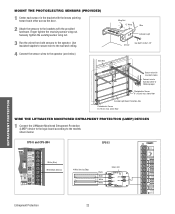
... both sensors to following page) Photoelectric Sensor 6" (15 cm) max. above floor WIRE THE LIFTMASTER MONITORED ENTRAPMENT PROTECTION (LMEP) DEVICES 1 Connect the LiftMaster Monitored Entrapment Protection (LMEP) device to the logic board according to the models shown below ). Bell Wire Wing Nut "C" Wrap Wire Indicator Light Sensor Hex Bolt 1/4-20x1-1/2" ENTRAPMENT PROTECTION...
... both sensors to following page) Photoelectric Sensor 6" (15 cm) max. above floor WIRE THE LIFTMASTER MONITORED ENTRAPMENT PROTECTION (LMEP) DEVICES 1 Connect the LiftMaster Monitored Entrapment Protection (LMEP) device to the logic board according to the models shown below ). Bell Wire Wing Nut "C" Wrap Wire Indicator Light Sensor Hex Bolt 1/4-20x1-1/2" ENTRAPMENT PROTECTION...
GT- Logic 4 Installation Manual
Page 24
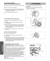
... designed to protect the door and motorized operator. We require the use of motor failures is eliminated. (Auxiliary Reversal System not applicable on models GH and GT.) NOTE: This feature is automatically learned and does not require programming. In addition, the RPM eliminates the need for primary safety...to allow PRECAUCIÓN the clutch to slip if the door is NOT a substitute for a safety sensing device. AVERTISSEMENT Torque Nut Set Screws MODEL GH (OPTIONAL MODIFICATION) 1 Loosen set screw that is directly over the flat portion of the door and to allow the reducer to slip...
... designed to protect the door and motorized operator. We require the use of motor failures is eliminated. (Auxiliary Reversal System not applicable on models GH and GT.) NOTE: This feature is automatically learned and does not require programming. In addition, the RPM eliminates the need for primary safety...to allow PRECAUCIÓN the clutch to slip if the door is NOT a substitute for a safety sensing device. AVERTISSEMENT Torque Nut Set Screws MODEL GH (OPTIONAL MODIFICATION) 1 Loosen set screw that is directly over the flat portion of the door and to allow the reducer to slip...
GT- Logic 4 Installation Manual
Page 26
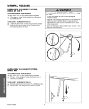
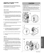
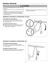
.... TO RECONNECT DOOR ARM TO TROLLEY 2 Lift free end of persons and obstructions. 1 AVERTISSEMENT ATTENTION 2 NOTICE MANUAL RELEASE EMERGENCY DISCONNECT SYSTEM MODEL APT TO DISCONNECT DOOR FROM OPERATOR The door should be in the fully closed position if possible. 1 Pull emergency release handle straight down on...by using the door control or remote. Pull emergency release handle to allow arm to trolley. MANUAL RELEASE EMERGENCY DISCONNECT SYSTEM MODEL GT AND T TO DISCONNECT DOOR FROM OPERATOR The door should be in the fully closed position if possible. 1 Pull down .
.... TO RECONNECT DOOR ARM TO TROLLEY 2 Lift free end of persons and obstructions. 1 AVERTISSEMENT ATTENTION 2 NOTICE MANUAL RELEASE EMERGENCY DISCONNECT SYSTEM MODEL APT TO DISCONNECT DOOR FROM OPERATOR The door should be in the fully closed position if possible. 1 Pull emergency release handle straight down on...by using the door control or remote. Pull emergency release handle to allow arm to trolley. MANUAL RELEASE EMERGENCY DISCONNECT SYSTEM MODEL GT AND T TO DISCONNECT DOOR FROM OPERATOR The door should be in the fully closed position if possible. 1 Pull down .
GT- Logic 4 Installation Manual
Page 27
...use emergency disconnect ONLY when door is CLOSED. HJ 4 27 3 4 2 1 Manual Release Refer to engage the hoist mechanism. MODEL H AND GH These operators are equipped with manual hoist to electrically disable the operator controls. 1 Pull the disconnect chain to the appropriate instructions below for...before the door will disable the electrical controls when the hoist is clear of emergency or power failure. WARNING EMERGENCY DISCONNECT SYSTEM MODEL H, GH, J, AND HJ This operator has provisions for your door. • If possible, use emergency disconnect unless doorway is used...
...use emergency disconnect ONLY when door is CLOSED. HJ 4 27 3 4 2 1 Manual Release Refer to engage the hoist mechanism. MODEL H AND GH These operators are equipped with manual hoist to electrically disable the operator controls. 1 Pull the disconnect chain to the appropriate instructions below for...before the door will disable the electrical controls when the hoist is clear of emergency or power failure. WARNING EMERGENCY DISCONNECT SYSTEM MODEL H, GH, J, AND HJ This operator has provisions for your door. • If possible, use emergency disconnect unless doorway is used...

GT- Logic 4 Installation Manual
Page 36
...Turn the SELECTOR DIAL to the desired wiring type. Return the SELECTOR DIAL to DIAG (diagnostic mode). 3. Bearings and Shafts LiftMaster Monitored Entrapment Protection (LMEP) Check for every 3 months. 6. MAINTENANCE 36 Maintenance Check alignment and functionality. z Inspect and ... in service. ITEM PROCEDURE Drive Chain Check for some models. Check and adjust as installed. Motor bearings are available. Call our TOLL FREE number: 1-800-528-2806 www.liftmaster.com LIFAEDOVFEORPETREATNOCRIFAEATURE (ODOMETER/CYCLE COUNATEDR)VERTENCIA The operator is ...
...Turn the SELECTOR DIAL to the desired wiring type. Return the SELECTOR DIAL to DIAG (diagnostic mode). 3. Bearings and Shafts LiftMaster Monitored Entrapment Protection (LMEP) Check for every 3 months. 6. MAINTENANCE 36 Maintenance Check alignment and functionality. z Inspect and ... in service. ITEM PROCEDURE Drive Chain Check for some models. Check and adjust as installed. Motor bearings are available. Call our TOLL FREE number: 1-800-528-2806 www.liftmaster.com LIFAEDOVFEORPETREATNOCRIFAEATURE (ODOMETER/CYCLE COUNATEDR)VERTENCIA The operator is ...
GT- Logic 4 Installation Manual
Page 41
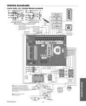
...VAC VAC (WH) NO COM C (YE) +24 VAC -24 VAC COIL (GY) NOTE: Lock Sensor is provided on Models DJ and DH only, red wire from main harness connects to NC on Bypass L/S and to NO on Open L/S. (WH)...WIRING DIAGRAM 115V MOTOR CONNECTION 230V MOTOR CONNECTION NOTE: Gray (GY) and purple (PU) motor wires are reversed for LiftMaster Monitored Entrapment Protection (LMEP) device connections Hoist Interlock When Present TMR DEF (BL) SWITCH (YE) Sensing Edge Maintenance... SENSOR switch to page 26 for H and HJ right hand models and all GH and J models. Refer to NC on LOCK SENSOR switch.
...VAC VAC (WH) NO COM C (YE) +24 VAC -24 VAC COIL (GY) NOTE: Lock Sensor is provided on Models DJ and DH only, red wire from main harness connects to NC on Bypass L/S and to NO on Open L/S. (WH)...WIRING DIAGRAM 115V MOTOR CONNECTION 230V MOTOR CONNECTION NOTE: Gray (GY) and purple (PU) motor wires are reversed for LiftMaster Monitored Entrapment Protection (LMEP) device connections Hoist Interlock When Present TMR DEF (BL) SWITCH (YE) Sensing Edge Maintenance... SENSOR switch to page 26 for H and HJ right hand models and all GH and J models. Refer to NC on LOCK SENSOR switch.
GT- Logic 4 Installation Manual
Page 42
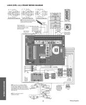
... and DH only, red wire from main harness connects to NC on BYPASS L/S and to page 26 for H and HJ right hand models and all GH and J models. POWER IN NOTE: Lock Sensor is located in the chassis. (WH) LOCK (RD) NO SENSOR (see note at left) NC (WH) NC ... (YE) (BL/BK) 208/230V MOTOR CONNECTION 460V MOTOR CONNECTION 575V MOTOR CONNECTION NOTE: Gray (GY) and purple (PU) motor wires are reversed for LiftMaster Monitored Entrapment Protection (LMEP) device connections Hoist Interlock When Present TMR DEF (BL) SWITCH (YE) Maintenance Alert LED (RD) (WH) Open Close Stop OPEN...
... and DH only, red wire from main harness connects to NC on BYPASS L/S and to page 26 for H and HJ right hand models and all GH and J models. POWER IN NOTE: Lock Sensor is located in the chassis. (WH) LOCK (RD) NO SENSOR (see note at left) NC (WH) NC ... (YE) (BL/BK) 208/230V MOTOR CONNECTION 460V MOTOR CONNECTION 575V MOTOR CONNECTION NOTE: Gray (GY) and purple (PU) motor wires are reversed for LiftMaster Monitored Entrapment Protection (LMEP) device connections Hoist Interlock When Present TMR DEF (BL) SWITCH (YE) Maintenance Alert LED (RD) (WH) Open Close Stop OPEN...
GT- Logic 4 User Manual
Page 6
... NOT stand under the door arm when pulling the emergency • NEVER use emergency release handle to engage roll pin. EMERGENCY DISCONNECT SYSTEM MODEL GT AND T TO DISCONNECT DOOR FROM OPERATOR The door should be in an open . 1 TO RECONNECT DOOR ARM TO TROLLEY ATTENTION ...obstructions. • If possible, use emergency release handle unless doorway is CLOSED. Release handle. AVE AV 2 NOTICE EMERGENCY DISCONNECT SYSTEM MODEL APT TO DISCONNECT DOOR FROM OPERATOR ADVERTENCIA The door should be in the fully closed position if possible. Pull emergency release handle to...
... NOT stand under the door arm when pulling the emergency • NEVER use emergency release handle to engage roll pin. EMERGENCY DISCONNECT SYSTEM MODEL GT AND T TO DISCONNECT DOOR FROM OPERATOR The door should be in an open . 1 TO RECONNECT DOOR ARM TO TROLLEY ATTENTION ...obstructions. • If possible, use emergency release handle unless doorway is CLOSED. Release handle. AVE AV 2 NOTICE EMERGENCY DISCONNECT SYSTEM MODEL APT TO DISCONNECT DOOR FROM OPERATOR ADVERTENCIA The door should be in the fully closed position if possible. Pull emergency release handle to...


