BG790 Manual
Page 2
... 4 PREPARATION Carton Inventory 5 Site Preparation 5 Operation Preparation 5 INSTALLATION Pad Mounting 6 Arm Fabrication 6 Calculate Arm Length 6 Wiring Specifications 7 Wiring Connections 7 Arm Attachment 8-9 Arm and Turnbuckle Shaft Adjustments 10 Limit Switch Adjustments 11 OPTIONAL ACCESSORIES Vehicle Detectors 12 Radio Controls...Voltage Circuit 15 Low Voltage Circuit 15 General Reference Information 15 REPAIR PARTS Illustrated Parts - Model BG770 16 Repair Parts - Model BG790 19 MAINTENANCE Limited Bearing Lubrication 20 Grease Turnbuckle 20 WIRING DIAGRAMS...
... 4 PREPARATION Carton Inventory 5 Site Preparation 5 Operation Preparation 5 INSTALLATION Pad Mounting 6 Arm Fabrication 6 Calculate Arm Length 6 Wiring Specifications 7 Wiring Connections 7 Arm Attachment 8-9 Arm and Turnbuckle Shaft Adjustments 10 Limit Switch Adjustments 11 OPTIONAL ACCESSORIES Vehicle Detectors 12 Radio Controls...Voltage Circuit 15 Low Voltage Circuit 15 General Reference Information 15 REPAIR PARTS Illustrated Parts - Model BG770 16 Repair Parts - Model BG790 19 MAINTENANCE Limited Bearing Lubrication 20 Grease Turnbuckle 20 WIRING DIAGRAMS...
BG790 Manual
Page 3
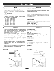
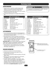
... open until CLOSE button is designated by third suffix of a loop detector to open and/or a loop detector to 24' ARM SPEED MODEL BG770: Opens in 4 seconds MODEL BG790: Opens in 11 seconds LUBRICATION Permanently lubricated bearings in connectors are included for addition of gate...24' DIMENSIONS 22" 44" 35" Typical Installation Typical Installation 3 Plug-in motor. MECHANICAL SPEED REDUCTION Wormgear-in-oil-bath, 60:1 ARM TYPE MODEL BG770: One piece type to 15' MODEL BG790: Counterweighted wishbone type to hold open loop detector is Mobil SHC 630 or equivalent. SPECIFICATIONS...
... open until CLOSE button is designated by third suffix of a loop detector to open and/or a loop detector to 24' ARM SPEED MODEL BG770: Opens in 4 seconds MODEL BG790: Opens in 11 seconds LUBRICATION Permanently lubricated bearings in connectors are included for addition of gate...24' DIMENSIONS 22" 44" 35" Typical Installation Typical Installation 3 Plug-in motor. MECHANICAL SPEED REDUCTION Wormgear-in-oil-bath, 60:1 ARM TYPE MODEL BG770: One piece type to 15' MODEL BG790: Counterweighted wishbone type to hold open loop detector is Mobil SHC 630 or equivalent. SPECIFICATIONS...
BG790 Manual
Page 4
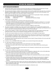
... and its function as the one on the bottom edge. All exposed pinch points are not obstructed or impeded by a moving part of a vertical barrier (arm). 4 Vehicular gate systems provide convenience and security. Outdoor or easily accessible controls shall have a security feature to potential hazards. 3. One or more contact sensors shall...
... and its function as the one on the bottom edge. All exposed pinch points are not obstructed or impeded by a moving part of a vertical barrier (arm). 4 Vehicular gate systems provide convenience and security. Outdoor or easily accessible controls shall have a security feature to potential hazards. 3. One or more contact sensors shall...
BG790 Manual
Page 5
MODEL BG770 PACKING LIST PART NUMBER DESCRIPTION QTY 02-102 Open/Close Push Button 1 07-8007 Gate Arm Hub 1 10-8007M Gate Bracket 1 80-G0187 Key, 1/2 x 1/2 x 1-3/8 1 82-NH38-06 Cone Point Set Screw, 3/8-16 x 3/8 2 82-HN50-25 Hex Bolt, 1/2-13 x 2-1/4 4 82-RH... power to the site according to supply the gate. MODEL BG790 PACKING LIST PART NUMBER DESCRIPTION QTY 02-102 Open/Close Push Button 1 07-8007 Arm Hub 2 10-8055 Counter Weight Clamp 2 80-G0135 Threaded Rod, 3/8-16 x 18 2 80-G0187 Key, 1/2 x 1/2 x 1-3/8 2 82-HN50-25 Hex Head Bolt, 1/2-13 x 2-1/4 12 ...
MODEL BG770 PACKING LIST PART NUMBER DESCRIPTION QTY 02-102 Open/Close Push Button 1 07-8007 Gate Arm Hub 1 10-8007M Gate Bracket 1 80-G0187 Key, 1/2 x 1/2 x 1-3/8 1 82-NH38-06 Cone Point Set Screw, 3/8-16 x 3/8 2 82-HN50-25 Hex Bolt, 1/2-13 x 2-1/4 4 82-RH... power to the site according to supply the gate. MODEL BG790 PACKING LIST PART NUMBER DESCRIPTION QTY 02-102 Open/Close Push Button 1 07-8007 Arm Hub 2 10-8055 Counter Weight Clamp 2 80-G0135 Threaded Rod, 3/8-16 x 18 2 80-G0187 Key, 1/2 x 1/2 x 1-3/8 2 82-HN50-25 Hex Head Bolt, 1/2-13 x 2-1/4 12 ...
BG790 Manual
Page 6
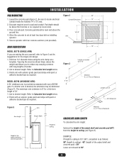
...ceiling) - 40" (height of the output shaft and concrete pad (40") from the height to Calculate Arm Length below . 3. Drill four 1/2" diameter holes using the arm clamp as required. Refer to ceiling (see Figure 5). Finish with an exterior grade paint and stripe with every...adhesive backed tape as a template. If a shorter arm is 8' for pad and conduit. Secure operator with four concrete anchors (not provided). 13" 22" ARM FABRICATION MODEL BG770 (SINGLE ARM) If you to Calculate Arm Length below . 2. Finish arm with exterior grade paint and stripe with long lengths of...
...ceiling) - 40" (height of the output shaft and concrete pad (40") from the height to Calculate Arm Length below . 3. Drill four 1/2" diameter holes using the arm clamp as required. Refer to ceiling (see Figure 5). Finish with an exterior grade paint and stripe with every...adhesive backed tape as a template. If a shorter arm is 8' for pad and conduit. Secure operator with four concrete anchors (not provided). 13" 22" ARM FABRICATION MODEL BG770 (SINGLE ARM) If you to Calculate Arm Length below . 2. Finish arm with exterior grade paint and stripe with long lengths of...
BG790 Manual
Page 8
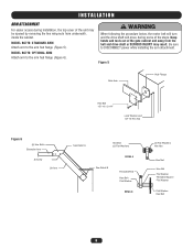
... Flange Hex Bolt 1/2"-13 x 2-1/4" Lock Washer and 1/2"-13 Hex Nut Figure 6 (4) Hex Bolts Extension Arm S Screw Lift Arm See Detail A Hex Bolt (2) Flat Washers DETAIL A See Detail B Threaded Rod Hex Bolt Flat Washer DETAIL B (2) Flat Washers Hex Nut Hex Nut Hex Nut ...be opened by removing the two wing nuts from the belt and drive shaft or SERIOUS INJURY may result. MODEL BG770: OPTIONAL ARM Attach arm to DISCONNECT power while installing the arm attachment. INSTALLATION ARM ATTACHMENT For easier access during some of the steps. Keep hands and tools out of the gate cabinet and ...
... Flange Hex Bolt 1/2"-13 x 2-1/4" Lock Washer and 1/2"-13 Hex Nut Figure 6 (4) Hex Bolts Extension Arm S Screw Lift Arm See Detail A Hex Bolt (2) Flat Washers DETAIL A See Detail B Threaded Rod Hex Bolt Flat Washer DETAIL B (2) Flat Washers Hex Nut Hex Nut Hex Nut ...be opened by removing the two wing nuts from the belt and drive shaft or SERIOUS INJURY may result. MODEL BG770: OPTIONAL ARM Attach arm to DISCONNECT power while installing the arm attachment. INSTALLATION ARM ATTACHMENT For easier access during some of the steps. Keep hands and tools out of the gate cabinet and ...
BG790 Manual
Page 9
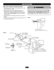
...(4) 3/8" Lock Washers (8) 3/8" Flat Washers (8) 1/2"-13 x 2-1/4" Hex Bolts Arm Clamp Counterweight (4) 1/2" Flat Washers (4) 1/2" Lock Washers (2) 1/2"-13 Hex Nuts 9 weights. 2. If an extension arm is required, sandwich the extension arm between the two halves of arms clamps (Figure 7). Be prepared for travel of the gate cabinet and away from ...the power on power and test the gate. Assemble the two 3/8" threaded rods to DISCONNECT power while installing the arm attachment. Turn on . WARNING When following the procedure below, the motor belt will move during some of the steps....
...(4) 3/8" Lock Washers (8) 3/8" Flat Washers (8) 1/2"-13 x 2-1/4" Hex Bolts Arm Clamp Counterweight (4) 1/2" Flat Washers (4) 1/2" Lock Washers (2) 1/2"-13 Hex Nuts 9 weights. 2. If an extension arm is required, sandwich the extension arm between the two halves of arms clamps (Figure 7). Be prepared for travel of the gate cabinet and away from ...the power on power and test the gate. Assemble the two 3/8" threaded rods to DISCONNECT power while installing the arm attachment. Turn on . WARNING When following the procedure below, the motor belt will move during some of the steps....
BG790 Manual
Page 10
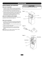
... Turn off power BEFORE making ANY adjustments. This is in a vertical position (Figure 11). If the arm is raising, the upper and lower cranks should be preset in the shaft. MODEL BG770 TURNBUCKLE SHAFT ALIGNMENT If necessary, align turnbuckle shaft with the turnbuckle shaft (Figure 9). NOTE: While the... arm is not level, loosen the jam nuts on the motor by hand until the gate arm is the lowest point of the arm travel and should travel...
... Turn off power BEFORE making ANY adjustments. This is in a vertical position (Figure 11). If the arm is raising, the upper and lower cranks should be preset in the shaft. MODEL BG770 TURNBUCKLE SHAFT ALIGNMENT If necessary, align turnbuckle shaft with the turnbuckle shaft (Figure 9). NOTE: While the... arm is not level, loosen the jam nuts on the motor by hand until the gate arm is the lowest point of the arm travel and should travel...
BG790 Manual
Page 11
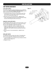
... pulley in the desired position, retighten the set screw on power and running the unit for the first time. When the cam is in section Arm and Turnbuckle Shaft Adjustments, you will activate just before the CLOSE switch. 2. OPEN LIMIT SWITCH The OPEN limit switch is preset at the factory. INSTALLATION... screw. If you made an adjustment to the CLOSE cam, you will need to be fine tuned after turning on the cam. When the gate arm is preset at the factory. Retighten the cam. When the cam is activated (Figure 12). 2. This adjustment may have to adjust the cam on its...
... pulley in the desired position, retighten the set screw on power and running the unit for the first time. When the cam is in section Arm and Turnbuckle Shaft Adjustments, you will activate just before the CLOSE switch. 2. OPEN LIMIT SWITCH The OPEN limit switch is preset at the factory. INSTALLATION... screw. If you made an adjustment to the CLOSE cam, you will need to be fine tuned after turning on the cam. When the gate arm is preset at the factory. Retighten the cam. When the cam is activated (Figure 12). 2. This adjustment may have to adjust the cam on its...
BG790 Manual
Page 13
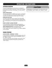
...) or automatic reset (3 phase unit) thermal overload protector. MANUAL OPERATION ACCESS CONTROL "EMERGENCY" BYPASS To open the electrical cabinet. The gate arm will trip when the motor temperature is set back to the "MANUAL" position. Exercise caution when resetting the overload. DO NOT ATTEMPT TO ...the toggle switch on the cover of the main electrical cabinet to the "MANUAL" position. OPERATING INSTRUCTIONS ELECTRICAL OPERATION The BG770 and BG790 barrier gate operators are designed to trip, consult a qualified service company. Flip the AUTO/MANUAL switch to the "OFF" position...
...) or automatic reset (3 phase unit) thermal overload protector. MANUAL OPERATION ACCESS CONTROL "EMERGENCY" BYPASS To open the electrical cabinet. The gate arm will trip when the motor temperature is set back to the "MANUAL" position. Exercise caution when resetting the overload. DO NOT ATTEMPT TO ...the toggle switch on the cover of the main electrical cabinet to the "MANUAL" position. OPERATING INSTRUCTIONS ELECTRICAL OPERATION The BG770 and BG790 barrier gate operators are designed to trip, consult a qualified service company. Flip the AUTO/MANUAL switch to the "OFF" position...
BG790 Manual
Page 17
... 24Vac DPDT Relay Switch Box Duplex Outlet Cover 1-32 x 1/8 Spacer Nylon Sensor Spacer Barrier Gate Gear Reducer 8 Position Terminal Block 10 Position Terminal Block Single Arm (Optional) 6-32 Tinnerman Nut 3/4 Flat Washer Access Panel Lock 1/2-20 x 1-1/4 Hex Head Bolt 3/4-10 x 3 Hex Head Bolt 3/4-16 Jam Nut 3/4-16...- 115/208/230Vac - 10-60Hz 8 Used on: BG770-50-11, 1 BG770-50-21, BG770-50-81 1 20-3050B-4E 1/2HP - 208/230/460Vac - 30-60Hz 1 Used on: BG770-50-23, 1 BG770-50-43, BG770-50-83 6 20-3050M-5 1/2HP - 575Vac - 30-60Hz 12 Used on: BG770-50-53 4 47 24-XXX-X Relay 1 24-115...
... 24Vac DPDT Relay Switch Box Duplex Outlet Cover 1-32 x 1/8 Spacer Nylon Sensor Spacer Barrier Gate Gear Reducer 8 Position Terminal Block 10 Position Terminal Block Single Arm (Optional) 6-32 Tinnerman Nut 3/4 Flat Washer Access Panel Lock 1/2-20 x 1-1/4 Hex Head Bolt 3/4-10 x 3 Hex Head Bolt 3/4-16 Jam Nut 3/4-16...- 115/208/230Vac - 10-60Hz 8 Used on: BG770-50-11, 1 BG770-50-21, BG770-50-81 1 20-3050B-4E 1/2HP - 208/230/460Vac - 30-60Hz 1 Used on: BG770-50-23, 1 BG770-50-43, BG770-50-83 6 20-3050M-5 1/2HP - 575Vac - 30-60Hz 12 Used on: BG770-50-53 4 47 24-XXX-X Relay 1 24-115...
BG790 Manual
Page 18
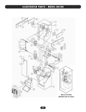
ILLUSTRATED PARTS - MODEL BG790 12 34 33 2 7 14 2 33 40 15 3 42 40 16 8 37 32 9 6 24 1 22 31 26 32 27 48 41 4 14 13 43 44 5 14 30 36 10 17 18 20 19 21 34 12 28 29 44 25 45 39 23 38 45 44 35 46 14 47 11 49 Operator Assembly (Wishbone Arm not shown) 18
ILLUSTRATED PARTS - MODEL BG790 12 34 33 2 7 14 2 33 40 15 3 42 40 16 8 37 32 9 6 24 1 22 31 26 32 27 48 41 4 14 13 43 44 5 14 30 36 10 17 18 20 19 21 34 12 28 29 44 25 45 39 23 38 45 44 35 46 14 47 11 49 Operator Assembly (Wishbone Arm not shown) 18
BG790 Manual
Page 19
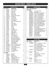
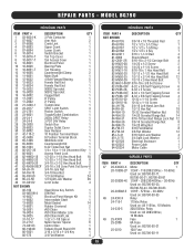
... 19-9024 19-9025 31-10-17 31-2712 74-G0133 80-1904N 80-5001 80-575 DESCRIPTION QTY 3 Pole Contactor 1 Arm Hub 2 Crank Link 1 Upper Crank 1 Lower Crank 1 Switch Bracket 1 Tan Top Cover 1 Tan Access Cover 1 Electrical ...Toggle/Outlet Combination 1 24Vac DPDT Relay 1 3 PDT 24V Relay 1 Switch Box 1 Duplex Outlet Cover 1 Gear Reducer 1 10 Position Terminal Block 1 8 Position Terminal Block 1 Wishbone Arm 1 Counterweight Kit 1 6-32 Tinnerman Nut 1 1/4 x 1/4 x 1-1/4 Disconnect Key 1 Access Panel Lock 1 1/2-20 x 1-1/4 Hex Head Bolt 18 1/2-20 x 1-1/2 Hex Head ...
... 19-9024 19-9025 31-10-17 31-2712 74-G0133 80-1904N 80-5001 80-575 DESCRIPTION QTY 3 Pole Contactor 1 Arm Hub 2 Crank Link 1 Upper Crank 1 Lower Crank 1 Switch Bracket 1 Tan Top Cover 1 Tan Access Cover 1 Electrical ...Toggle/Outlet Combination 1 24Vac DPDT Relay 1 3 PDT 24V Relay 1 Switch Box 1 Duplex Outlet Cover 1 Gear Reducer 1 10 Position Terminal Block 1 8 Position Terminal Block 1 Wishbone Arm 1 Counterweight Kit 1 6-32 Tinnerman Nut 1 1/4 x 1/4 x 1-1/4 Disconnect Key 1 Access Panel Lock 1 1/2-20 x 1-1/4 Hex Head Bolt 18 1/2-20 x 1-1/2 Hex Head ...
BG790 Manual
Page 21
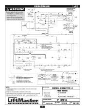
... R1 (Y) IR (OR) CLOSE SEE NOTE 1 24V SEC. (W) (PUR) 1) REMOVE JUMPER WHEN TIMER TO CLOSE IS USED. 2) REMOVE JUMPER TO CAUSE GATE ARM TO CLOSE IMMEDIATELY UNLESS HOLD OPEN LOOP IS ACTIVATED. (OR) OP 56 1 CL 2 (1 of rating. WIRING DIAGRAM To protect against fire and electrocution: •...8226; Replace ONLY with fuse of same type of 2) MOTOR CONNECTION SAME AS INCOMING POWER. APPLICATIONS: CONTROL WIRING TYPE L2 MODEL TYPES: FIELD WIRING BG770, BG790 HORSEPOWER: VOLTAGE/PHASE: 1/2 115/230V, 60Hz, 1 PHASE ONLY DRAWING NUMBER: DATE: 08/28/00 01-G1014 REVISION: F-3/20/08 ECN: ...
... R1 (Y) IR (OR) CLOSE SEE NOTE 1 24V SEC. (W) (PUR) 1) REMOVE JUMPER WHEN TIMER TO CLOSE IS USED. 2) REMOVE JUMPER TO CAUSE GATE ARM TO CLOSE IMMEDIATELY UNLESS HOLD OPEN LOOP IS ACTIVATED. (OR) OP 56 1 CL 2 (1 of rating. WIRING DIAGRAM To protect against fire and electrocution: •...8226; Replace ONLY with fuse of same type of 2) MOTOR CONNECTION SAME AS INCOMING POWER. APPLICATIONS: CONTROL WIRING TYPE L2 MODEL TYPES: FIELD WIRING BG770, BG790 HORSEPOWER: VOLTAGE/PHASE: 1/2 115/230V, 60Hz, 1 PHASE ONLY DRAWING NUMBER: DATE: 08/28/00 01-G1014 REVISION: F-3/20/08 ECN: ...
BG790 Manual
Page 22
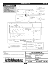
...CLOSE IS USED. 24V COIL (OR) R1 (GN) R2 (GN) (OR) 14 OP 13 (OR) (OR) R1 (Y) CLOSE 5 TD-2 2) REMOVE JUMPER TO CAUSE GATE ARM TO CLOSE IMMEDIATELY UNLESS HOLD OPEN LOOP IS ACTIVATED 24V COIL (OR) (OR) CLOSE L/S (BL) 24V COIL OP NO C (OR) TD1 24VAC DPDT HOLD OPEN... 24V SECONDARY 2) WE RECOMMEND USING A DEDICATED CIRCUIT BREAKER FOR EACH OPERATOR. 1 APPLICATIONS: CONTROL WIRING TYPE FIELD WIRING & ADJUSTMENTS MODEL TYPES: HORSEPOWER: VOLTAGE/PHASE: BG770 (PG) BG790 (HBG) 1/2 208/230/480/575V DRAWING NUMBER: 01-G1015 DATE: 08/28/00 REVISION: E-3/20/08 ECN: 08-7165 22
...CLOSE IS USED. 24V COIL (OR) R1 (GN) R2 (GN) (OR) 14 OP 13 (OR) (OR) R1 (Y) CLOSE 5 TD-2 2) REMOVE JUMPER TO CAUSE GATE ARM TO CLOSE IMMEDIATELY UNLESS HOLD OPEN LOOP IS ACTIVATED 24V COIL (OR) (OR) CLOSE L/S (BL) 24V COIL OP NO C (OR) TD1 24VAC DPDT HOLD OPEN... 24V SECONDARY 2) WE RECOMMEND USING A DEDICATED CIRCUIT BREAKER FOR EACH OPERATOR. 1 APPLICATIONS: CONTROL WIRING TYPE FIELD WIRING & ADJUSTMENTS MODEL TYPES: HORSEPOWER: VOLTAGE/PHASE: BG770 (PG) BG790 (HBG) 1/2 208/230/480/575V DRAWING NUMBER: 01-G1015 DATE: 08/28/00 REVISION: E-3/20/08 ECN: 08-7165 22
BG790 Manual
Page 23
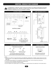
IT WILL NOT STOP OR CLOSE THE GATE. IF THIS JUMPER IS NOT REMOVED, ARM WILL REMAIN OPEN UNTIL A VEHICLE ENTERS AND EXITS THE HOLD OPEN LOOP. 2) ADD JUMPER FROM TERMINAL #8 TO #9 WHENEVER CLOSE BUTTON IS USED. FAILURE TO COMPLY ... CONNECTION DIAGRAM IT IS IMPORTANT TO READ ALL SAFETY RULES INCLUDED IN THE INSTALLATION MANUAL BEFORE BEGINNING INSTALLATION. NOTES: 1) REMOVE THIS JUMPER TO CAUSE GATE ARM TO CLOSE IMMEDIATELY WHENEVER IT IS OPENED, UNLESS A VEHICLE IS ON THE HOLD OPEN LOOP. DO NOT USE WITH HOLD OPEN LOOP. 3) 115V UTILITY OUTLET...
IT WILL NOT STOP OR CLOSE THE GATE. IF THIS JUMPER IS NOT REMOVED, ARM WILL REMAIN OPEN UNTIL A VEHICLE ENTERS AND EXITS THE HOLD OPEN LOOP. 2) ADD JUMPER FROM TERMINAL #8 TO #9 WHENEVER CLOSE BUTTON IS USED. FAILURE TO COMPLY ... CONNECTION DIAGRAM IT IS IMPORTANT TO READ ALL SAFETY RULES INCLUDED IN THE INSTALLATION MANUAL BEFORE BEGINNING INSTALLATION. NOTES: 1) REMOVE THIS JUMPER TO CAUSE GATE ARM TO CLOSE IMMEDIATELY WHENEVER IT IS OPENED, UNLESS A VEHICLE IS ON THE HOLD OPEN LOOP. DO NOT USE WITH HOLD OPEN LOOP. 3) 115V UTILITY OUTLET...


