ATS2113X Manual
Page 2
... 29 To add or change a Keyless Entry PIN (Optional 30 Multi-Function door control (Optional 31 Repair Parts 32-33 Rail assembly parts 32 Installation parts 32 Motor unit assembly parts 33 Accessories 34 Notes 35 Repair Parts and Service 36 Warranty 36 INTRODUCTION Safety Symbol and Signal Word Review This garage door opener has...
... 29 To add or change a Keyless Entry PIN (Optional 30 Multi-Function door control (Optional 31 Repair Parts 32-33 Rail assembly parts 32 Installation parts 32 Motor unit assembly parts 33 Accessories 34 Notes 35 Repair Parts and Service 36 Warranty 36 INTRODUCTION Safety Symbol and Signal Word Review This garage door opener has...
ATS2113X Manual
Page 5
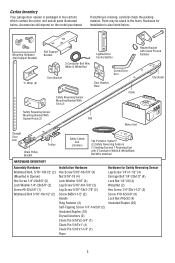
Carton Inventory Your garage door opener is packaged in two cartons which contain the motor unit and all parts illustrated below . Hardware for Safety Reversing Sensor Lag Screw 1/4"x1-1/2" (4) Carriage Bolt 1/4"-20x1/2" (4) Lock Nut 1/4"-20 (4) Wing Nut ...1 Receiving Eye) with 2-Conductor White & White/Black Bell Wire attached HARDWARE INVENTORY Assembly Hardware Washered Bolt, 5/16"-18x1/2" (2) (Mounted in the foam. Parts may be stuck in Opener) Hex Screw 1/4"-20x5/8" (2) Lock Washer 1/4"-20x5/8" (2) Screw #8-32x3/8" (1) Washered Bolt 5/16"-18x1/2" (2) Installation Hardware Hex ...
Carton Inventory Your garage door opener is packaged in two cartons which contain the motor unit and all parts illustrated below . Hardware for Safety Reversing Sensor Lag Screw 1/4"x1-1/2" (4) Carriage Bolt 1/4"-20x1/2" (4) Lock Nut 1/4"-20 (4) Wing Nut ...1 Receiving Eye) with 2-Conductor White & White/Black Bell Wire attached HARDWARE INVENTORY Assembly Hardware Washered Bolt, 5/16"-18x1/2" (2) (Mounted in the foam. Parts may be stuck in Opener) Hex Screw 1/4"-20x5/8" (2) Lock Washer 1/4"-20x5/8" (2) Screw #8-32x3/8" (1) Washered Bolt 5/16"-18x1/2" (2) Installation Hardware Hex ...
ATS2113X Manual
Page 6
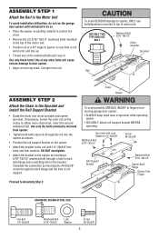
... Bolt 5/16"-18x1/2" Chain Spreader Sprocket Rail ASSEMBLY STEP 2 Attach the Chain to Assembly Step 3. Insert the second washered bolt. Use of the washered bolts part way in the bracket. Use only the bolts previously removed from opener. • Tighten both bolts securely through the rail into the opener as shown...
... Bolt 5/16"-18x1/2" Chain Spreader Sprocket Rail ASSEMBLY STEP 2 Attach the Chain to Assembly Step 3. Insert the second washered bolt. Use of the washered bolts part way in the bracket. Use only the bolts previously removed from opener. • Tighten both bolts securely through the rail into the opener as shown...

ATS2113X Manual
Page 7
... position shown when the door is approximately 1/2" (1.27 cm) above the base of the rail at minimum height of 5 feet (1.5 m). • away from ALL moving parts of installation, test safety reversal system. NEVER wear watches, rings or loose clothing while installing or servicing opener. ASSEMBLY STEP 3 Tighten the Chain • Spin...
... position shown when the door is approximately 1/2" (1.27 cm) above the base of the rail at minimum height of 5 feet (1.5 m). • away from ALL moving parts of installation, test safety reversal system. NEVER wear watches, rings or loose clothing while installing or servicing opener. ASSEMBLY STEP 3 Tighten the Chain • Spin...
ATS2113X Manual
Page 12
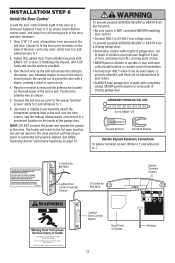
...NOT connect the power and operate the opener at a minimum height of 5 feet (1.5 m) where small children cannot reach, and away from all moving parts of door. • NEVER permit children to operate or play with door control push buttons or remote control transmitters. • Activate door ONLY when.... See Safety Reversing Sensor instructions beginning on the inside of the garage door. To prevent possible SERIOUS INJURY or DEATH from ALL moving parts of the door and door hardware. 1. INSTALLATION STEP 6 Install the Door Control Locate the door control within sight of garage door, ...
...NOT connect the power and operate the opener at a minimum height of 5 feet (1.5 m) where small children cannot reach, and away from all moving parts of door. • NEVER permit children to operate or play with door control push buttons or remote control transmitters. • Activate door ONLY when.... See Safety Reversing Sensor instructions beginning on the inside of the garage door. To prevent possible SERIOUS INJURY or DEATH from ALL moving parts of the door and door hardware. 1. INSTALLATION STEP 6 Install the Door Control Locate the door control within sight of garage door, ...
ATS2113X Manual
Page 15
... open position, and the opener lights will flash 10 times. The invisible light beam path must be securely fastened to the receiving eye. No part of the garage door (or door tracks, springs, hinges, rollers or other across the door, no more than 6" (15 cm) above floor 15 above...
... open position, and the opener lights will flash 10 times. The invisible light beam path must be securely fastened to the receiving eye. No part of the garage door (or door tracks, springs, hinges, rollers or other across the door, no more than 6" (15 cm) above floor 15 above...
ATS2113X Manual
Page 26
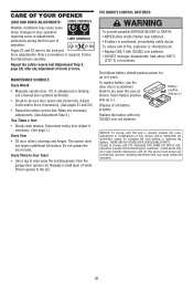
... grease to 5 years. To replace battery, use the visor clip or screwdriver blade to the limit and force adjustments. THERE ARE NO OTHER USER SERVICEABLE PARTS. CARE OF YOUR OPENER LIMIT AND FORCE ADJUSTMENTS: FORCE CONTROLS Weather conditions may cause some minor changes in door operation requiring some re-adjustments, particularly...
... grease to 5 years. To replace battery, use the visor clip or screwdriver blade to the limit and force adjustments. THERE ARE NO OTHER USER SERVICEABLE PARTS. CARE OF YOUR OPENER LIMIT AND FORCE ADJUSTMENTS: FORCE CONTROLS Weather conditions may cause some minor changes in door operation requiring some re-adjustments, particularly...
ATS2113X Manual
Page 31
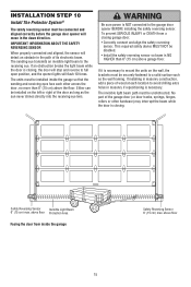
..., the Lock and Light features will not control clip or small flat a minimum height of 5 feet (1.5 m), and away from ALL moving parts of the door and door hardware. Fasten with care to avoid cracking plastic Press the push button to turn the Light Button cover after mounting...connect the power and operate the opener Lock feature at a minimum height of 5 feet (1.5 m) where small children cannot reach, and away from moving parts of door. • NEVER permit children to operate or play with door control push buttons or remote control transmitters. • Activate door ONLY when ...
..., the Lock and Light features will not control clip or small flat a minimum height of 5 feet (1.5 m), and away from ALL moving parts of the door and door hardware. Fasten with care to avoid cracking plastic Press the push button to turn the Light Button cover after mounting...connect the power and operate the opener Lock feature at a minimum height of 5 feet (1.5 m) where small children cannot reach, and away from moving parts of door. • NEVER permit children to operate or play with door control push buttons or remote control transmitters. • Activate door ONLY when ...
ATS2113X Manual
Page 32
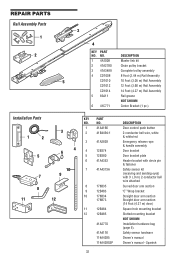
... arm section Straight door arm section (14 Foot (4.27 m) door) Square hole mounting bracket Slotted mounting bracket NOT SHOWN Installation hardware bag (page 5). REPAIR PARTS Rail Assembly Parts 1 2 3 4 KEY PART NO. DESCRIPTION 1 4A1008 Master link kit 2 41A2780 Chain pulley bracket 3 41A3489 Complete trolley assembly 4 CD1008 8 Foot (2.44 m) Rail Assembly 5 CD1010 10 Foot (3.05...
... arm section Straight door arm section (14 Foot (4.27 m) door) Square hole mounting bracket Slotted mounting bracket NOT SHOWN Installation hardware bag (page 5). REPAIR PARTS Rail Assembly Parts 1 2 3 4 KEY PART NO. DESCRIPTION 1 4A1008 Master link kit 2 41A2780 Chain pulley bracket 3 41A3489 Complete trolley assembly 4 CD1008 8 Foot (2.44 m) Rail Assembly 5 CD1010 10 Foot (3.05...

ATS2113X Manual
Page 33
... board, end panel with all labels NOT SHOWN 41A2825 Opener assembly hardware kit (includes screws not designated by a number in illustration). 33 Motor Unit Assembly Parts 1 2 3 4 15 18 18 17 16 7 9 8 5 6 (Down) Contact Brown Wire Drive Gear Center Limit Contact 15 14 LIMIT SWITCH ASSEMBLY Grey Wire (UP) Contact Yellow Wire...
... board, end panel with all labels NOT SHOWN 41A2825 Opener assembly hardware kit (includes screws not designated by a number in illustration). 33 Motor Unit Assembly Parts 1 2 3 4 15 18 18 17 16 7 9 8 5 6 (Down) Contact Brown Wire Drive Gear Center Limit Contact 15 14 LIMIT SWITCH ASSEMBLY Grey Wire (UP) Contact Yellow Wire...

ATS2113X Manual
Page 36
... warranty gives you specific legal rights, and you . SIMPLY DIAL OUR TOLL FREE NUMBER: 1-800-528-9131 www.liftmaster.com For professional installation, parts and service, contact your area. Country Club Road Tucson, Arizona 85706 SERVICE INFORMATION TOLL FREE NUMBER: 1-800-528-9131... LIFTMASTER® ONE YEAR LIMITED WARRANTY LIFETIME MOTOR LIMITED WARRANTY The Chamberlain Group, Inc. ("Seller") warrants to comply strictly with new or factory-rebuilt parts at no cost to be defective and covered by this limited...
... warranty gives you specific legal rights, and you . SIMPLY DIAL OUR TOLL FREE NUMBER: 1-800-528-9131 www.liftmaster.com For professional installation, parts and service, contact your area. Country Club Road Tucson, Arizona 85706 SERVICE INFORMATION TOLL FREE NUMBER: 1-800-528-9131... LIFTMASTER® ONE YEAR LIMITED WARRANTY LIFETIME MOTOR LIMITED WARRANTY The Chamberlain Group, Inc. ("Seller") warrants to comply strictly with new or factory-rebuilt parts at no cost to be defective and covered by this limited...


