3900PLD Manual
Page 1
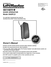
® DOOR OPERATOR Model 3900PLD For Light Duty Commercial Use Install On Sectional Doors With Torsion Assemblies Only The Chamberlain Group, Inc. 845 Larch Avenue Elmhurst, Illinois 60126-1196 www.liftmaster.com patible with Com Details Owner's Manual See Page 13 for ■ Please read this ...manual and the enclosed safety materials carefully! ■ Fasten the manual near the door after installation. ■ The door WILL NOT CLOSE ...
® DOOR OPERATOR Model 3900PLD For Light Duty Commercial Use Install On Sectional Doors With Torsion Assemblies Only The Chamberlain Group, Inc. 845 Larch Avenue Elmhurst, Illinois 60126-1196 www.liftmaster.com patible with Com Details Owner's Manual See Page 13 for ■ Please read this ...manual and the enclosed safety materials carefully! ■ Fasten the manual near the door after installation. ■ The door WILL NOT CLOSE ...
3900PLD Manual
Page 2
... program or change a keyless entry PIN (Not Provided 27 Programming remote light (Not Provided 28 Repair Parts 29 Installation parts 29 Motor unit assembly parts 29 Accessories 30 Notes 31 Repair Parts and Service 32 INTRODUCTION Safety Symbol Review and... bracket to the operator 6 Installation 7-16 Installation safety instructions 7 Position the operator 7 Attach the emergency release rope and handle 8 Install power door lock (Not Provided 8 Attach the cable tension monitor (Required 9 Install the single button control station 10 Install the light (Not Provided 11...
... program or change a keyless entry PIN (Not Provided 27 Programming remote light (Not Provided 28 Repair Parts 29 Installation parts 29 Motor unit assembly parts 29 Accessories 30 Notes 31 Repair Parts and Service 32 INTRODUCTION Safety Symbol Review and... bracket to the operator 6 Installation 7-16 Installation safety instructions 7 Position the operator 7 Attach the emergency release rope and handle 8 Install power door lock (Not Provided 8 Attach the cable tension monitor (Required 9 Install the single button control station 10 Install the light (Not Provided 11...
3900PLD Manual
Page 3
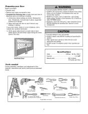
...• The torsion bar must not exceed 1/4" (6 mm). 3 m). • 1" (2.5 cm) torsion bar only. • Review or inspect proposed installation area. Otherwise the safety reversal system may be required. Must have minimum of 2-1/2" (6.4 cm) between the ceiling and the center of torsion bar. - Depending...; An electric outlet is no noticeable movement up to 180 sq. Operator can be used on your requirements, there are several installation steps which may find it helpful to refer back to this page as this operator will require hardware not provided. • ...
...• The torsion bar must not exceed 1/4" (6 mm). 3 m). • 1" (2.5 cm) torsion bar only. • Review or inspect proposed installation area. Otherwise the safety reversal system may be required. Must have minimum of 2-1/2" (6.4 cm) between the ceiling and the center of torsion bar. - Depending...; An electric outlet is no noticeable movement up to 180 sq. Operator can be used on your requirements, there are several installation steps which may find it helpful to refer back to this page as this operator will require hardware not provided. • ...
3900PLD Manual
Page 4
...damage. • DO NOT exceed 10 complete cycles of balance, call a trained door systems technician. 3. Sectional Door Tools needed During assembly, installation and adjustment of the door. If balanced, it should remain equal during the entire travel of the operator, instructions will call a trained door ...INJURY or DEATH: • ALWAYS call for hand tools as shown. To prevent damage to door and operator: • ALWAYS disable locks BEFORE installing and operating the operator. • ONLY operate door operator at 120V, 60 Hz to loosen, move or adjust door, door springs, cables,...
...damage. • DO NOT exceed 10 complete cycles of balance, call a trained door systems technician. 3. Sectional Door Tools needed During assembly, installation and adjustment of the door. If balanced, it should remain equal during the entire travel of the operator, instructions will call a trained door ...INJURY or DEATH: • ALWAYS call for hand tools as shown. To prevent damage to door and operator: • ALWAYS disable locks BEFORE installing and operating the operator. • ONLY operate door operator at 120V, 60 Hz to loosen, move or adjust door, door springs, cables,...

3900PLD Manual
Page 5
... Collar with Screws The Protector System® (2) Safety Reversing Sensors (1 Sending Eye and 1 Receiving Eye) with 2-Conductor White & White/Black Bell Wire attached Hardware Inventory INSTALLATION HARDWARE Hex Screw #14-10x1-7/8" (4) Screw #6x-1-1/4" (2) Machine Screw #6x1" (2) Carriage Bolt 1/4"-20x1/2" (2) Wing Nut 1/4"-20 (2) Pan Head Screw 1/4"-20x1/2" (2) Hex Head Screw #8x1" (2) Self...
... Collar with Screws The Protector System® (2) Safety Reversing Sensors (1 Sending Eye and 1 Receiving Eye) with 2-Conductor White & White/Black Bell Wire attached Hardware Inventory INSTALLATION HARDWARE Hex Screw #14-10x1-7/8" (4) Screw #6x-1-1/4" (2) Machine Screw #6x1" (2) Carriage Bolt 1/4"-20x1/2" (2) Wing Nut 1/4"-20 (2) Pan Head Screw 1/4"-20x1/2" (2) Hex Head Screw #8x1" (2) Self...
3900PLD Manual
Page 6
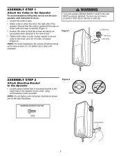
...up for left or the right side of collar screws equally to secure collar to the motor unit (12-14 ft./lbs. NOTE: For most installations the screws should be lost due to collar slip. The door may not reverse correctly or limits may be facing up (accessible when attached to...-32 WRONG Socket Wrench 6 of the operator as the collar, using self-threading screws provided. ASSEMBLY STEP 1 Attach the Collar to the Operator To avoid installation difficulties, do not run the door operator until instructed to do so. • Loosen the collar screws. • Attach collar to either the left side...
...up for left or the right side of collar screws equally to secure collar to the motor unit (12-14 ft./lbs. NOTE: For most installations the screws should be lost due to collar slip. The door may not reverse correctly or limits may be facing up (accessible when attached to...-32 WRONG Socket Wrench 6 of the operator as the collar, using self-threading screws provided. ASSEMBLY STEP 1 Attach the Collar to the Operator To avoid installation difficulties, do not run the door operator until instructed to do so. • Loosen the collar screws. • Attach collar to either the left side...
3900PLD Manual
Page 7
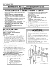
...connect door operator to power source until pilot holes align with 14-10x1-7/8" screws. NEVER wear watches, rings or loose clothing while installing or servicing operator. Install the entrapment warning placard next to 12-14 ft./lbs. Upon completion of door. 11. Door MUST reverse on contact with a... 1-1/2" (3.8 cm) high object (or a 2x4 laid flat) on the collar. INSTALLATION STEP 1 Position the Operator NOTE: For additional mounting options see accessories page. 1. Slide the operator with collar over the torsion bar until instructed...
...connect door operator to power source until pilot holes align with 14-10x1-7/8" screws. NEVER wear watches, rings or loose clothing while installing or servicing operator. Install the entrapment warning placard next to 12-14 ft./lbs. Upon completion of door. 11. Door MUST reverse on contact with a... 1-1/2" (3.8 cm) high object (or a 2x4 laid flat) on the collar. INSTALLATION STEP 1 Position the Operator NOTE: For additional mounting options see accessories page. 1. Slide the operator with collar over the torsion bar until instructed...
3900PLD Manual
Page 8
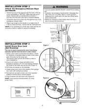
...center of persons and obstructions. Fasten power door lock to cut the rope, heat seal the cut end with an overhand knot. Motor Unit INSTALLATION STEP 3 Install Power Door Lock (Not Provided) The lock is used to prevent the door from a falling door: • If possible, use emergency ... to the outside of the power head. If possible select a roller on the template. 4. Select a door roller to secure wire in most installations. 2. Use insulated staples to mount the lock above the floor. Run bell wire up as the motor unit. Emergency Release Cable Overhand Knot Rope...
...center of persons and obstructions. Fasten power door lock to cut the rope, heat seal the cut end with an overhand knot. Motor Unit INSTALLATION STEP 3 Install Power Door Lock (Not Provided) The lock is used to prevent the door from a falling door: • If possible, use emergency ... to the outside of the power head. If possible select a roller on the template. 4. Select a door roller to secure wire in most installations. 2. Use insulated staples to mount the lock above the floor. Run bell wire up as the motor unit. Emergency Release Cable Overhand Knot Rope...

3900PLD Manual
Page 9
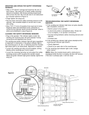
...to the green quick-connect terminals (polarity is detected, eliminating service calls. NOTE: Cable must be located as close to secure wire in the installation area that may occur and will move in tab with screwdriver tip Screw #6 (2) Wall Anchor (2) 9 Figure 1 Operator Torsion Bar Drum Cable ...Hex Head Screw (2) Staples To insert or release wire, push in the down direction. If required, it can be connected and properly installed before the door operator will reverse the door when excessive slack is not important) (Figure 3). Make sure cable tension monitor is on...
...to the green quick-connect terminals (polarity is detected, eliminating service calls. NOTE: Cable must be located as close to secure wire in the installation area that may occur and will move in tab with screwdriver tip Screw #6 (2) Wall Anchor (2) 9 Figure 1 Operator Torsion Bar Drum Cable ...Hex Head Screw (2) Staples To insert or release wire, push in the down direction. If required, it can be connected and properly installed before the door operator will reverse the door when excessive slack is not important) (Figure 3). Make sure cable tension monitor is on...

3900PLD Manual
Page 10
...Play in the Door Area Keep Door in Sight at all Times When Door is Moving WWHHTT//RREEDD WWHHTT Door Control Connections SSiinngglleeBBuutttoonnCCoonnttrroollSSttaattiioonn Factory installed jumper must be smooth and flat. 3. Operator will not function without the jumper. 10 Remove the control station cover. 2. Connect wires... NE PAS FAIRE FONCTIONNER LA PORTE PLUS DE 10 FOIS PAR HEURE. NEVER permit anyone to cross path of closing door: • Install door control within sight of door, out of reach of door. • NEVER permit children to operate or play with door control ...
...Play in the Door Area Keep Door in Sight at all Times When Door is Moving WWHHTT//RREEDD WWHHTT Door Control Connections SSiinngglleeBBuutttoonnCCoonnttrroollSSttaattiioonn Factory installed jumper must be smooth and flat. 3. Operator will not function without the jumper. 10 Remove the control station cover. 2. Connect wires... NE PAS FAIRE FONCTIONNER LA PORTE PLUS DE 10 FOIS PAR HEURE. NEVER permit anyone to cross path of closing door: • Install door control within sight of door, out of reach of door. • NEVER permit children to operate or play with door control ...
3900PLD Manual
Page 11
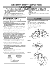
... outlet ONLY one way. 3. Use ONLY incandescent. To prevent damage to the operator: • DO NOT use with the screws provided. INSTALLATION STEP 6 Install the Light (Not Provided) The remote light (operator light) is required for ceiling mount and indoor applications ONLY. See Programming Remote Light. ... reverse the plug. 4. This plug will not operate until the unit is wider than 100W. • ONLY use halogen bulbs. Install the light base by hooking one blade is activated. IMPORTANT SAFETY INSTRUCTIONS WARNING To reduce the risk of power cord needed to reach the...
... outlet ONLY one way. 3. Use ONLY incandescent. To prevent damage to the operator: • DO NOT use with the screws provided. INSTALLATION STEP 6 Install the Light (Not Provided) The remote light (operator light) is required for ceiling mount and indoor applications ONLY. See Programming Remote Light. ... reverse the plug. 4. This plug will not operate until the unit is wider than 100W. • ONLY use halogen bulbs. Install the light base by hooking one blade is activated. IMPORTANT SAFETY INSTRUCTIONS WARNING To reduce the risk of power cord needed to reach the...

3900PLD Manual
Page 12
... CONNECTION RIGHT WRONG If permanent wiring is not connected to the operator, and disconnect power to circuit BEFORE removing cover to install the proper outlet. This plug will only fit into the outlet you have, contact a qualified electrician to establish permanent wiring connection. &#... PERMANENT WIRING CONNECTION Green Wire Black Wire White Wire 90˚ Connector 12 To prevent possible SERIOUS INJURY or DEATH from unit. • Install a 90o conduit or flex cable adapter to the following procedure. Be sure the operator is grounded. To reduce the risk of insulation, ...
... CONNECTION RIGHT WRONG If permanent wiring is not connected to the operator, and disconnect power to circuit BEFORE removing cover to install the proper outlet. This plug will only fit into the outlet you have, contact a qualified electrician to establish permanent wiring connection. &#... PERMANENT WIRING CONNECTION Green Wire Black Wire White Wire 90˚ Connector 12 To prevent possible SERIOUS INJURY or DEATH from unit. • Install a 90o conduit or flex cable adapter to the following procedure. Be sure the operator is grounded. To reduce the risk of insulation, ...

3900PLD Manual
Page 13
... 8 Mount the Standby Power Unit (SPU) (Not Provided) If the optional 475LM Standby Power Unit is part of this installation it should be installed at this time. • The SPU can be mounted to either the ceiling or a wall within 3' (.9 m) of the motor unit. • Position the SPU as ...
... 8 Mount the Standby Power Unit (SPU) (Not Provided) If the optional 475LM Standby Power Unit is part of this installation it should be installed at this time. • The SPU can be mounted to either the ceiling or a wall within 3' (.9 m) of the motor unit. • Position the SPU as ...
3900PLD Manual
Page 14
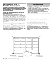
... in masonry if repositioning is necessary. If an obstruction breaks the light beam while the door is a required safety device and cannot be installed inside the garage 14 Safety Reversing Sensor 6" (15 cm) max. Extension brackets (see accessories) are designed to a solid surface such...beam path must be disabled. above floor. Be sure power is closing door: • Correctly connect and align the safety reversing sensor. If installing in masonry construction, add a piece of the door (door tracks, springs, hinges, rollers or other across the door, no more than 6"...
... in masonry if repositioning is necessary. If an obstruction breaks the light beam while the door is a required safety device and cannot be installed inside the garage 14 Safety Reversing Sensor 6" (15 cm) max. Extension brackets (see accessories) are designed to a solid surface such...beam path must be disabled. above floor. Be sure power is closing door: • Correctly connect and align the safety reversing sensor. If installing in masonry construction, add a piece of the door (door tracks, springs, hinges, rollers or other across the door, no more than 6"...

3900PLD Manual
Page 15
...IWnsaildl e WALL MOUNT (RIGHT SIDE) Fasten Wood Block to elevate sensor brackets so the lenses will not support the bracket securely, wall installation is recommended. Door track installation (preferred) (Figure 1): • Slip the curved arms over the rounded edge of the door, no higher than 6" (15 ...and place right and left assemblies to the operator is needed, an extension bracket (See Accessories) or wood blocks can be installed in Figure 1. Install and align the brackets so the safety reversing sensors will face each side of each door track, with Concrete Anchors (Not ...
...IWnsaildl e WALL MOUNT (RIGHT SIDE) Fasten Wood Block to elevate sensor brackets so the lenses will not support the bracket securely, wall installation is recommended. Door track installation (preferred) (Figure 1): • Slip the curved arms over the rounded edge of the door, no higher than 6" (15 ...and place right and left assemblies to the operator is needed, an extension bracket (See Accessories) or wood blocks can be installed in Figure 1. Install and align the brackets so the safety reversing sensors will face each side of each door track, with Concrete Anchors (Not ...
3900PLD Manual
Page 16
... white/black wires. When the green indicator light glows steadily, tighten the wing nut. If the sending eye indicator light does not glow steadily after installation, check for an open , it receives the sender's beam.
... white/black wires. When the green indicator light glows steadily, tighten the wing nut. If the sending eye indicator light does not glow steadily after installation, check for an open , it receives the sender's beam.

3900PLD Manual
Page 17
... and the door should open ) and purple moves the door DOWN (close). To prevent damage to vehicles, be tested. Figure 1 LED Black Button Without a properly installed safety reversal system, persons (particularly small children) could be too much pressure on contact with proper operation of the door by a closing the door (Figure...
... and the door should open ) and purple moves the door DOWN (close). To prevent damage to vehicles, be tested. Figure 1 LED Black Button Without a properly installed safety reversal system, persons (particularly small children) could be too much pressure on contact with proper operation of the door by a closing the door (Figure...
3900PLD Manual
Page 18
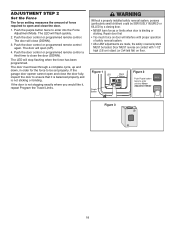
... The force setting measures the amount of safety reversal system. • After ANY adjustments are made, the safety reversal system MUST be tested. Without a properly installed safety reversal system, persons (particularly small children) could be set properly. Push the purple button twice to be SERIOUSLY INJURED or KILLED by a closing door...
... The force setting measures the amount of safety reversal system. • After ANY adjustments are made, the safety reversal system MUST be tested. Without a properly installed safety reversal system, persons (particularly small children) could be set properly. Push the purple button twice to be SERIOUSLY INJURED or KILLED by a closing door...
3900PLD Manual
Page 19
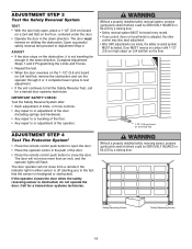
...made, the safety reversal system MUST be SERIOUSLY INJURED or KILLED by a closing door. Call for a trained door systems technician. Without a properly installed safety reversal system, persons (particularly small children) could be SERIOUSLY INJURED or KILLED by a closing door. • Safety reversal system MUST be... door. ADJUST • If the door stops on the floor. 1-1/2" (3.8 cm) board (or a 2x4 laid flat) Without a properly installed safety reversing sensor, persons (particularly small children) could be tested. The door must reverse on striking the obstruction.
...made, the safety reversal system MUST be SERIOUSLY INJURED or KILLED by a closing door. Call for a trained door systems technician. Without a properly installed safety reversal system, persons (particularly small children) could be SERIOUSLY INJURED or KILLED by a closing door. • Safety reversal system MUST be... door. ADJUST • If the door stops on the floor. 1-1/2" (3.8 cm) board (or a 2x4 laid flat) Without a properly installed safety reversing sensor, persons (particularly small children) could be tested. The door must reverse on striking the obstruction.
3900PLD Manual
Page 21
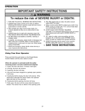
... controls. 3. SAVE THESE INSTRUCTIONS. When the operator is activated (with 1-1/2" (3.8 cm) high object (or a 2x4 laid flat) on contact with the safety reversing sensor correctly installed and aligned) 1. If closed . If obstructed while closing , the door will blink for five seconds. 6. WARNING OPERATION IMPORTANT SAFETY INSTRUCTIONS WARNING To reduce the risk...
... controls. 3. SAVE THESE INSTRUCTIONS. When the operator is activated (with 1-1/2" (3.8 cm) high object (or a 2x4 laid flat) on contact with the safety reversing sensor correctly installed and aligned) 1. If closed . If obstructed while closing , the door will blink for five seconds. 6. WARNING OPERATION IMPORTANT SAFETY INSTRUCTIONS WARNING To reduce the risk...


