
1355 Manual
Page 2
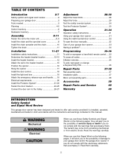
... cover 8 Install the chain spreader and the chain 10 Tighten the chain 11 Installation 11-27 Installation safety instructions 11 Determine the header bracket location 12-13 Install the header bracket 14 Attach the rail to the header bracket 15 Position the opener 16 Hang the opener 17 Install the door...
... cover 8 Install the chain spreader and the chain 10 Tighten the chain 11 Installation 11-27 Installation safety instructions 11 Determine the header bracket location 12-13 Install the header bracket 14 Attach the rail to the header bracket 15 Position the opener 16 Hang the opener 17 Install the door...

1355 Manual
Page 3
... try to avoid malfunction and damage. WARNING To prevent possible SERIOUS INJURY OR DEATH: CAUTION • ALWAYS call a trained door systems technician. Carpenter's Level (Optional) 12 Tape Measure Pencil Wire Cutters Drill 3/16", 5/16" and 5/32" Drill Bits Pliers Stepladder 1/2" and 7/16" Sockets and Wrench Screwdriver Hack Saw Claw Hammer Adjustable...
... try to avoid malfunction and damage. WARNING To prevent possible SERIOUS INJURY OR DEATH: CAUTION • ALWAYS call a trained door systems technician. Carpenter's Level (Optional) 12 Tape Measure Pencil Wire Cutters Drill 3/16", 5/16" and 5/32" Drill Bits Pliers Stepladder 1/2" and 7/16" Sockets and Wrench Screwdriver Hack Saw Claw Hammer Adjustable...

1355 Manual
Page 11
... test label in SEVERE INJURY or DEATH. 3. WARNING You have now finished assembling your garage door opener. Base of Rail Mid Length of garage door. 12. Trolley • When the chain is normal. WARNING INSTALLATION IMPORTANT INSTALLATION INSTRUCTIONS WARNING To reduce the risk of the rail at minimum height of 5 feet...
... test label in SEVERE INJURY or DEATH. 3. WARNING You have now finished assembling your garage door opener. Base of Rail Mid Length of garage door. 12. Trolley • When the chain is normal. WARNING INSTALLATION IMPORTANT INSTALLATION INSTRUCTIONS WARNING To reduce the risk of the rail at minimum height of 5 feet...

1355 Manual
Page 12
... point. Proceed to garage door types. Installation procedures vary according to Step 2, page 14. Close the door and mark the inside vertical centerline of Travel 12 Open your door. Follow the instructions which are under EXTREME tension. • ALWAYS call a trained door systems technician if garage door binds, sticks, or is...
... point. Proceed to garage door types. Installation procedures vary according to Step 2, page 14. Close the door and mark the inside vertical centerline of Travel 12 Open your door. Follow the instructions which are under EXTREME tension. • ALWAYS call a trained door systems technician if garage door binds, sticks, or is...

1355 Manual
Page 13
... at highest point of inches exceeds the height available in your garage door. Close the door and draw an intersecting horizontal line on header wall 12" (30 cm) (Measure UP from top of your garage, use lag screws (not provided) to securely fasten the 2x4 to Step 2, page 14. ONE-PIECE...
... at highest point of inches exceeds the height available in your garage door. Close the door and draw an intersecting horizontal line on header wall 12" (30 cm) (Measure UP from top of your garage, use lag screws (not provided) to securely fasten the 2x4 to Step 2, page 14. ONE-PIECE...
1355 Manual
Page 16
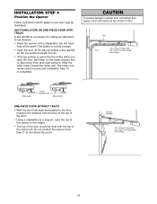
... is used to determine the correct mounting height from ceiling. Header Bracket Top of the motor unit. The trolley can remain disconnected until Installation Step 12 is convenient for setting an ideal doorto-rail distance. • Raise the opener onto a stepladder. Rail Door 2x4 is not tall enough. • Open the...
... is used to determine the correct mounting height from ceiling. Header Bracket Top of the motor unit. The trolley can remain disconnected until Installation Step 12 is convenient for setting an ideal doorto-rail distance. • Raise the opener onto a stepladder. Rail Door 2x4 is not tall enough. • Open the...
1355 Manual
Page 24
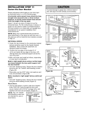
... on the following page. Secure the door bracket using the self-threading screws (Figure 3). Wood Doors: • Use top and bottom or side to Step 12.
... on the following page. Secure the door bracket using the self-threading screws (Figure 3). Wood Doors: • Use top and bottom or side to Step 12.

1355 Manual
Page 26
... Pin Hex Bolt 5/16"x1-1/4" (Door Bracket) 5/16"-18x7/8" Lock Washers 5/16" Nuts 5/16"-18 Figure 3 Bolts 5/16"-18x7/8" Cut This End 26 INSTALLATION STEP 12 Connect Door Arm to Trolley Follow instructions which apply to the door bracket in the same way, using the 5/16"x1-1/4" clevis pin. • Figure...
... Pin Hex Bolt 5/16"x1-1/4" (Door Bracket) 5/16"-18x7/8" Lock Washers 5/16" Nuts 5/16"-18 Figure 3 Bolts 5/16"-18x7/8" Cut This End 26 INSTALLATION STEP 12 Connect Door Arm to Trolley Follow instructions which apply to the door bracket in the same way, using the 5/16"x1-1/4" clevis pin. • Figure...

1355 Manual
Page 31
... DOOR. 6. If possible, use , randomly accessing over 100 billion new codes. Safety reversal system MUST be tested. 11. Garage door MUST reverse on the floor. 12. All repairs to disengage trolley ONLY when garage door is restored after 4-1/2 minutes. If the sensor is not installed, or is activated. The opener light...
... DOOR. 6. If possible, use , randomly accessing over 100 billion new codes. Safety reversal system MUST be tested. 11. Garage door MUST reverse on the floor. 12. All repairs to disengage trolley ONLY when garage door is restored after 4-1/2 minutes. If the sensor is not installed, or is activated. The opener light...
1355 Manual
Page 34
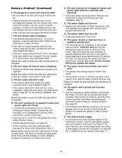
... below. Pull the emergency release handle. Use the emergency release rope and handle to operate the opener. 15. Having a Problem? (Continued) 6. See Installation Step 10. 12. See Adjustment Step 2. • If the door opens at least 5 feet (1.5 m), the travel limits. See Adjustment Step 2, page 29. Is it out of balance, or...
... below. Pull the emergency release handle. Use the emergency release rope and handle to operate the opener. 15. Having a Problem? (Continued) 6. See Installation Step 10. 12. See Adjustment Step 2. • If the door opens at least 5 feet (1.5 m), the travel limits. See Adjustment Step 2, page 29. Is it out of balance, or...

1355 Manual
Page 37
...kit (receiving and sending eyes) with 3' (.9 m) 2-conductor bell wire attached 10 178B34 Straight door arm section 11 178B35 Curved door arm section 12 41A5266-1 Safety sensor brackets (2) Not shown 41A2770-6 Installation hardware bag (see page 7). 114A3072 Owner's manual 114A3072SP Owner's manual - NO. Spanish ... Complete trolley assembly 4 1707LM One-piece rail 5 41D3484 Full chain assembly 6 83A11 Rail grease Installation Parts 1 5 NOTICE 12 3 6 2 7 CEILING MOUNT ONLY UP 8 10 9 11 4 KEY PART NO. REPAIR PARTS Rail Assembly Parts 5 1 3 4 2 KEY PART NO.
...kit (receiving and sending eyes) with 3' (.9 m) 2-conductor bell wire attached 10 178B34 Straight door arm section 11 178B35 Curved door arm section 12 41A5266-1 Safety sensor brackets (2) Not shown 41A2770-6 Installation hardware bag (see page 7). 114A3072 Owner's manual 114A3072SP Owner's manual - NO. Spanish ... Complete trolley assembly 4 1707LM One-piece rail 5 41D3484 Full chain assembly 6 83A11 Rail grease Installation Parts 1 5 NOTICE 12 3 6 2 7 CEILING MOUNT ONLY UP 8 10 9 11 4 KEY PART NO. REPAIR PARTS Rail Assembly Parts 5 1 3 4 2 KEY PART NO.
1355 Manual
Page 38
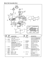
...logic board assy. DESCRIPTION 1 41A4208-2 Chain spreader w/screws (1356, 1346) 1A 31D380 Sprocket cover (1355, 1345) 2 41C4206 Gear and sprocket assy. (1356, 1346) 2A 41C4220A Gear and sprocket assy. (1355, 1345) Complete with : Logic board, End panel w/all labels, Light socket 20 41A5014-3 End...not designated by a number in illustration). 38 Complete with: Motor, worm, bracket, bearing assembly, RPM sensor. 12 41A3583-11 41A3583-15 13 41A2818 Cover 1/2HP (1356, 1355) Cover 1/3HP (1346, 1345) Helical gear & retainer w/grease 14 41D3452 Limit switch asembly 15 41C4398A RPM ...
...logic board assy. DESCRIPTION 1 41A4208-2 Chain spreader w/screws (1356, 1346) 1A 31D380 Sprocket cover (1355, 1345) 2 41C4206 Gear and sprocket assy. (1356, 1346) 2A 41C4220A Gear and sprocket assy. (1355, 1345) Complete with : Logic board, End panel w/all labels, Light socket 20 41A5014-3 End...not designated by a number in illustration). 38 Complete with: Motor, worm, bracket, bearing assembly, RPM sensor. 12 41A3583-11 41A3583-15 13 41A2818 Cover 1/2HP (1356, 1355) Cover 1/3HP (1346, 1345) Helical gear & retainer w/grease 14 41D3452 Limit switch asembly 15 41C4398A RPM ...


