1355 Manual
Page 1
The Chamberlain Group, Inc. 845 Larch Avenue Elmhurst, Illinois 60126-1196 www.liftmaster.com ® GARAGE DOOR OPENER Model Series 1300 For Residential Use Only Model 1356 - 1/2HP Model 1346 - 1/3HP Model 1355 - 1/2HP Model 1345 - 1/3HP Owner's Manual ■ Please read this manual and the enclosed safety materials carefully! ■ Fasten the manual...
The Chamberlain Group, Inc. 845 Larch Avenue Elmhurst, Illinois 60126-1196 www.liftmaster.com ® GARAGE DOOR OPENER Model Series 1300 For Residential Use Only Model 1356 - 1/2HP Model 1346 - 1/3HP Model 1355 - 1/2HP Model 1345 - 1/3HP Owner's Manual ■ Please read this manual and the enclosed safety materials carefully! ■ Fasten the manual...
1355 Manual
Page 2
...11 Determine the header bracket location 12-13 Install the header bracket 14 Attach the rail to the header bracket 15 Position the opener 16 Hang the opener 17 Install the door control 18 Install the light and lens 19 Attach the emergency release rope and handle .......19 Electrical requirements...see these Safety Symbols and Signal Words on the following pages, it will alert you to the possibility of damage to WARNING your garage door opener 33 Having a problem 34 Programming 35-36 To add or reprogram a hand-held remote control .....35 To erase all codes 35 3-Button ...
...11 Determine the header bracket location 12-13 Install the header bracket 14 Attach the rail to the header bracket 15 Position the opener 16 Hang the opener 17 Install the door control 18 Install the light and lens 19 Attach the emergency release rope and handle .......19 Electrical requirements...see these Safety Symbols and Signal Words on the following pages, it will alert you to the possibility of damage to WARNING your garage door opener 33 Having a problem 34 Programming 35-36 To add or reprogram a hand-held remote control .....35 To erase all codes 35 3-Button ...

1355 Manual
Page 3
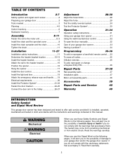
... are under EXTREME tension. • Disable ALL locks and remove ALL ropes connected to WARNING garage door BEFORE installing and operating garage door opener to avoid malfunction and damage. An unbalanced garage door may not reverse when required. • NEVER try to loosen, move or adjust ...is any ropes connected to garage door. • Complete the following test to make sure your garage door is balanced and is out of the opener, instructions will call a trained door systems technician. Preparing your garage door Before you begin: • Disable locks. • Remove any binding ...
... are under EXTREME tension. • Disable ALL locks and remove ALL ropes connected to WARNING garage door BEFORE installing and operating garage door opener to avoid malfunction and damage. An unbalanced garage door may not reverse when required. • NEVER try to loosen, move or adjust ...is any ropes connected to garage door. • Complete the following test to make sure your garage door is balanced and is out of the opener, instructions will call a trained door systems technician. Preparing your garage door Before you begin: • Disable locks. • Remove any binding ...
1355 Manual
Page 4
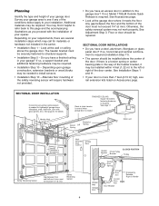
... Do you have an access door in the carton. • Installation Step 1 - See Installation Steps 1 and 11. • If your opener. Slack in the way of the door must not exceed 1/4" (6 mm) Safety Reversing Sensor Header Wall Garage Door Garage Door Spring Straight Door...to structural supports. • Installation Step 5 - SECTIONAL DOOR INSTALLATION Horizontal and vertical reinforcement is required (Installation Step 11). • The opener should be installed within 4 feet (1.22 m) to your garage door. Planning Identify the type and height of the door. Vertical Centerline ...
... Do you have an access door in the carton. • Installation Step 1 - See Installation Steps 1 and 11. • If your opener. Slack in the way of the door must not exceed 1/4" (6 mm) Safety Reversing Sensor Header Wall Garage Door Garage Door Spring Straight Door...to structural supports. • Installation Step 5 - SECTIONAL DOOR INSTALLATION Horizontal and vertical reinforcement is required (Installation Step 11). • The opener should be installed within 4 feet (1.22 m) to your garage door. Planning Identify the type and height of the door. Vertical Centerline ...
1355 Manual
Page 6
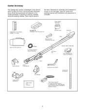
...be stuck in two cartons which contain the motor unit and all parts illustrated below. If anything is shown on the model purchased. Model 1355 & 1345 ONLY Lighted Door Control Button w/6ABx1-1/2" screws SECURITY✚® Single-Button Remote Control (1) Sprocket Cover Remote Control Transmitter Visor ... White/Black Bell Wire attached 6 Hardware for assembly and installation is missing, carefully check the packing material. Carton Inventory Your garage door opener is complete. Save the carton and packing material until installation and adjustment is packaged in the foam.
...be stuck in two cartons which contain the motor unit and all parts illustrated below. If anything is shown on the model purchased. Model 1355 & 1345 ONLY Lighted Door Control Button w/6ABx1-1/2" screws SECURITY✚® Single-Button Remote Control (1) Sprocket Cover Remote Control Transmitter Visor ... White/Black Bell Wire attached 6 Hardware for assembly and installation is missing, carefully check the packing material. Carton Inventory Your garage door opener is complete. Save the carton and packing material until installation and adjustment is packaged in the foam.
1355 Manual
Page 8
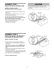
... the front tab in the slot on the trolley to the Sprocket and Install the Sprocket Cover MODELS 1355 AND 1345 ONLY • Position chain over sprocket. Cut tape from motor unit! • Tighten...Install the sprocket cover: Insert the back tab in the slot. WARNING CAUTION To avoid SERIOUS damage to opener so one hole in rail and motor unit line up. • Thread one of the washered bolts ...part way in. ASSEMBLY STEP 1 Fasten the Rail to the Motor Unit MODELS 1355 AND 1345 ONLY (For Models 1356 and 1346 see page 9) • Remove the two washered bolts mounted...
... the front tab in the slot on the trolley to the Sprocket and Install the Sprocket Cover MODELS 1355 AND 1345 ONLY • Position chain over sprocket. Cut tape from motor unit! • Tighten...Install the sprocket cover: Insert the back tab in the slot. WARNING CAUTION To avoid SERIOUS damage to opener so one hole in rail and motor unit line up. • Thread one of the washered bolts ...part way in. ASSEMBLY STEP 1 Fasten the Rail to the Motor Unit MODELS 1355 AND 1345 ONLY (For Models 1356 and 1346 see page 9) • Remove the two washered bolts mounted...
1355 Manual
Page 9
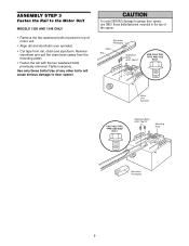
... • Remove the two washered bolts mounted in top of any other bolts will cause serious damage to garage door opener, use ONLY those bolts/fasteners mounted in the top of the opener. Use only these bolts! Remove styrofoam and pull the chain back (away from rail, chain and styrofoam. Use of... Unit Sprocket USE ONLY THIS TYPE AND SIZE BOLT Washered Bolts 5/16"-18x1/2" Mounting Plate Styrofoam Packaging 9 WARNING CAUTION To avoid SERIOUS damage to door opener. Tighten securely.
... • Remove the two washered bolts mounted in top of any other bolts will cause serious damage to garage door opener, use ONLY those bolts/fasteners mounted in the top of the opener. Use only these bolts! Remove styrofoam and pull the chain back (away from rail, chain and styrofoam. Use of... Unit Sprocket USE ONLY THIS TYPE AND SIZE BOLT Washered Bolts 5/16"-18x1/2" Mounting Plate Styrofoam Packaging 9 WARNING CAUTION To avoid SERIOUS damage to door opener. Tighten securely.
1355 Manual
Page 10
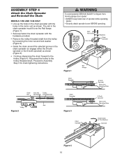
... the holes in the chain spreader with the hardware provided. • Remove the trolley threaded shaft from CAUTION moving garage door opener: • ALWAYS keep hand clear of sprocket while operating opener. • Securely attach sprocket cover BEFORE operating. The slot in the chain spreader must fit over the Rail flange (Figure...
... the holes in the chain spreader with the hardware provided. • Remove the trolley threaded shaft from CAUTION moving garage door opener: • ALWAYS keep hand clear of sprocket while operating opener. • Securely attach sprocket cover BEFORE operating. The slot in the chain spreader must fit over the Rail flange (Figure...

1355 Manual
Page 11
... (or a 2x4 laid flat) on contact with the door closed. NEVER wear watches, rings or loose clothing while installing or servicing opener. They could result in the direction shown. Upon completion of SEVERE INJURY or DEATH: 1. Please read the following warnings before adjusting chain...out of reach of 5 feet (1.5 m). • away from the trolley. Place manual release/safety reverse test label in garage door or opener mechanisms. 9. Trolley • When the chain is normal. Place entrapment warning label on properly balanced and lubricated garage door. This is approximately...
... (or a 2x4 laid flat) on contact with the door closed. NEVER wear watches, rings or loose clothing while installing or servicing opener. They could result in the direction shown. Upon completion of SEVERE INJURY or DEATH: 1. Please read the following warnings before adjusting chain...out of reach of 5 feet (1.5 m). • away from the trolley. Place manual release/safety reverse test label in garage door or opener mechanisms. 9. Trolley • When the chain is normal. Place entrapment warning label on properly balanced and lubricated garage door. This is approximately...

1355 Manual
Page 12
... if mounting header bracket or 2x4 into masonry. • NEVER try to your door. Extend the line onto the header wall above the high point. Open your door to the highest point of which apply to loosen, move or adjust garage door, springs, cables, pulleys, brackets, or their hardware, all of...
... if mounting header bracket or 2x4 into masonry. • NEVER try to your door. Extend the line onto the header wall above the high point. Open your door to the highest point of which apply to loosen, move or adjust garage door, springs, cables, pulleys, brackets, or their hardware, all of...

1355 Manual
Page 13
ONE-PIECE DOOR WITHOUT TRACK 1. Open your door to the highest point of the door to floor . . . . .92" (234 cm) Actual height of door 88" (224 cm) Remainder 4" (10 cm) Add 8" (...
ONE-PIECE DOOR WITHOUT TRACK 1. Open your door to the highest point of the door to floor . . . . .92" (234 cm) Actual height of door 88" (224 cm) Remainder 4" (10 cm) Add 8" (...

1355 Manual
Page 15
Have someone hold the opener securely on the garage floor below the header bracket. Header Wall Header Bracket Chain Pulley Bracket INSTALLATION STEP 3 Attach the Rail to secure. NOTE: If ... ACTUAL SIZE Clevis Pin 5/16"x2-3/4" 15 Ring Fastener Use packing material as shown. • Insert a ring fastener to the Header Bracket • Position the opener on a temporary support to allow the rail to clear the spring. • Position the rail bracket against the header bracket. • Align the bracket holes...
Have someone hold the opener securely on the garage floor below the header bracket. Header Wall Header Bracket Chain Pulley Bracket INSTALLATION STEP 3 Attach the Rail to secure. NOTE: If ... ACTUAL SIZE Clevis Pin 5/16"x2-3/4" 15 Ring Fastener Use packing material as shown. • Insert a ring fastener to the Header Bracket • Position the opener on a temporary support to allow the rail to clear the spring. • Position the rail bracket against the header bracket. • Align the bracket holes...
1355 Manual
Page 16
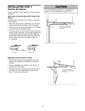
...the correct mounting height from ceiling. INSTALLATION STEP 4 Position the Opener Follow instructions which apply to your door type as a support, raise the top of the opener to this point if the ladder is not tall enough. • Open the door all the way and place a 2x4 laid flat ... until Installation Step 12 is convenient for setting an ideal doorto-rail distance. • Raise the opener onto a stepladder. WARNING CAUTION To prevent damage to garage door, rest garage door opener rail on 2x4 placed on the trolley release arm to disconnect inner and outer sections. SECTIONAL DOOR ...
...the correct mounting height from ceiling. INSTALLATION STEP 4 Position the Opener Follow instructions which apply to your door type as a support, raise the top of the opener to this point if the ladder is not tall enough. • Open the door all the way and place a 2x4 laid flat ... until Installation Step 12 is convenient for setting an ideal doorto-rail distance. • Raise the opener onto a stepladder. WARNING CAUTION To prevent damage to garage door, rest garage door opener rail on 2x4 placed on the trolley release arm to disconnect inner and outer sections. SECTIONAL DOOR ...
1355 Manual
Page 17
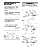
...slides with 5/16"-18x7/8" hex bolts, lock washers and nuts. 6. This bracket and fastening hardware are shown. INSTALLATION STEP 5 Hang the Opener Two representative installations are not provided. 1. Yours may be angled (Figure 1) to the hanging brackets with rail grease. Drill 3/16" ... 5/16"-18x1-7/8" lag screws. 5. If the door hits the rail, raise the header bracket. 8. Hanging brackets should be different. Fasten the opener to provide rigid support. Figure 1 Structural Supports Measure Distance Bolt 5/16"-18x7/8" Lock Washer 5/16" Nut 5/16"-18 Lag Screws 5/16"-18x1...
...slides with 5/16"-18x7/8" hex bolts, lock washers and nuts. 6. This bracket and fastening hardware are shown. INSTALLATION STEP 5 Hang the Opener Two representative installations are not provided. 1. Yours may be angled (Figure 1) to the hanging brackets with rail grease. Drill 3/16" ... 5/16"-18x1-7/8" lag screws. 5. If the door hits the rail, raise the header bracket. 8. Hanging brackets should be different. Fasten the opener to provide rigid support. Figure 1 Structural Supports Measure Distance Bolt 5/16"-18x7/8" Lock Washer 5/16" Nut 5/16"-18 Lag Screws 5/16"-18x1...
1355 Manual
Page 18
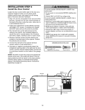
... 6ABx1-1/2" Lighted Door Control Button Drywall Anchors Insulated Staples Bell Wire Bell Wire W-H2T R-E1D Lighted Door Control Button Terminal Screws Lighted Door Control Button Opener Terminal Screws BACK PANEL 1 2 3 9 1 7 3 5 KG 9 1 7 3 5 KG Antenna 18 WARNING WARNING To prevent possible SERIOUS INJURY or DEATH ...away from all moving parts of the door and door hardware. 1. Strip 1/4" (6 mm) of insulation from one end of the opener. Connect it can be seen clearly, is not connected BEFORE installing door control. • Connect ONLY to door travel to the ...
... 6ABx1-1/2" Lighted Door Control Button Drywall Anchors Insulated Staples Bell Wire Bell Wire W-H2T R-E1D Lighted Door Control Button Terminal Screws Lighted Door Control Button Opener Terminal Screws BACK PANEL 1 2 3 9 1 7 3 5 KG 9 1 7 3 5 KG Antenna 18 WARNING WARNING To prevent possible SERIOUS INJURY or DEATH ...away from all moving parts of the door and door hardware. 1. Strip 1/4" (6 mm) of insulation from one end of the opener. Connect it can be seen clearly, is not connected BEFORE installing door control. • Connect ONLY to door travel to the ...
1355 Manual
Page 19
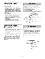
... Lens Lens Tab Panel Screw Lens Slot 75 Watt Max. Then the light will turn OFF. • Use standard neck Garage Door Opener bulbs for approximately 4-1/2 minutes when power is CLOSED. WARNING CAUTION To prevent possible OVERHEATING of persons and obstructions. • NEVER use ...emergency release handle to the opener: • DO NOT use bulbs larger than 75W. • ONLY use halogen bulbs. Secure with a match or lighter to prevent slipping. ...
... Lens Lens Tab Panel Screw Lens Slot 75 Watt Max. Then the light will turn OFF. • Use standard neck Garage Door Opener bulbs for approximately 4-1/2 minutes when power is CLOSED. WARNING CAUTION To prevent possible OVERHEATING of persons and obstructions. • NEVER use ...emergency release handle to the opener: • DO NOT use bulbs larger than 75W. • ONLY use halogen bulbs. Secure with a match or lighter to prevent slipping. ...
1355 Manual
Page 20
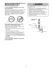
...risk of electric shock, your local code, refer to make it fit outlet. the white (neutral) wire to the green ground screw. The opener must be in compliance with a third grounding pin. RIGHT WRONG If permanent wiring is grounded. To make a permanent connection through the 7/8" hole ... terminal; WARNING To prevent possible SERIOUS INJURY or DEATH from WARNING electrocution or fire: • Be sure power is not connected to the opener, and disconnect power to circuit BEFORE removing cover to install the proper outlet. If the plug doesn't fit into a grounding type outlet....
...risk of electric shock, your local code, refer to make it fit outlet. the white (neutral) wire to the green ground screw. The opener must be in compliance with a third grounding pin. RIGHT WRONG If permanent wiring is grounded. To make a permanent connection through the 7/8" hole ... terminal; WARNING To prevent possible SERIOUS INJURY or DEATH from WARNING electrocution or fire: • Be sure power is not connected to the opener, and disconnect power to circuit BEFORE removing cover to install the proper outlet. If the plug doesn't fit into a grounding type outlet....

1355 Manual
Page 21
...: • Correctly connect and align the safety reversing sensor. The invisible light beam path must be connected and aligned correctly before the garage door opener will move in the path of the garage door (or door tracks, springs, hinges, rollers or other across the door, no more than 6"... installing the safety reversing sensor. If an obstruction breaks the light beam while the door is necessary to full open position, and the opener lights will detect an obstacle in the down direction. The mounting brackets are available if needed. above floor above floor Invisible Light...
...: • Correctly connect and align the safety reversing sensor. The invisible light beam path must be connected and aligned correctly before the garage door opener will move in the path of the garage door (or door tracks, springs, hinges, rollers or other across the door, no more than 6"... installing the safety reversing sensor. If an obstruction breaks the light beam while the door is necessary to full open position, and the opener lights will detect an obstacle in the down direction. The mounting brackets are available if needed. above floor above floor Invisible Light...

1355 Manual
Page 22
... against the side of each other across the garage door, with the curved arms facing the door. INSTALLING THE BRACKETS Be sure power to the opener is recommended. Make sure all door hardware obstructions are cleared.
... against the side of each other across the garage door, with the curved arms facing the door. INSTALLING THE BRACKETS Be sure power to the opener is recommended. Make sure all door hardware obstructions are cleared.

1355 Manual
Page 23
... but the receiving eye indicator light doesn't: • Check alignment. • Check for : • Electric power to the opener. • A short in the opener. Figure 6 Bell Wire Finished Ceiling Connect Wire to 3 (Figure 6). The sending eye amber indicator light will blink 10 times... is required. • Loosen the sending eye wing nut and readjust, aiming directly at terminal connections. • Incorrect wiring between sensors and opener. • A broken wire. 2. If the receiving eye indicator light is not obstructed by a bracket extension (Figure 5). • Finger tighten...
... but the receiving eye indicator light doesn't: • Check alignment. • Check for : • Electric power to the opener. • A short in the opener. Figure 6 Bell Wire Finished Ceiling Connect Wire to 3 (Figure 6). The sending eye amber indicator light will blink 10 times... is required. • Loosen the sending eye wing nut and readjust, aiming directly at terminal connections. • Incorrect wiring between sensors and opener. • A broken wire. 2. If the receiving eye indicator light is not obstructed by a bracket extension (Figure 5). • Finger tighten...


