Service Manual
Page 6
... and exit deflector removal 4-18 Controller board removal 4-19 Developer unit removal 4-21 Duplex sensor removal 4-21 Exit deflector and bin full sensor flag removal 4-24 Fuser assembly removal 4-26 Fuser drive motor assembly removal 4-29 Fuser exit sensor removal 4-30 High-voltage power supply (HVPS) assembly removal 4-31 Image transfer unit (ITU) removal 4-33 Imaging unit (IU) removal 4-35 Low-voltage...
... and exit deflector removal 4-18 Controller board removal 4-19 Developer unit removal 4-21 Duplex sensor removal 4-21 Exit deflector and bin full sensor flag removal 4-24 Fuser assembly removal 4-26 Fuser drive motor assembly removal 4-29 Fuser exit sensor removal 4-30 High-voltage power supply (HVPS) assembly removal 4-31 Image transfer unit (ITU) removal 4-33 Imaging unit (IU) removal 4-35 Low-voltage...
Service Manual
Page 37
...Check the location of toner. To print a menu settings page: 1. Press Menu ( ) on the operator panel (Settings->General Settings->Timeouts->Print Timeout.) • Remove and flex the paper in the tray. Select Menu Settings, and press Select ( ). • Increase the Print Timeout value on the operator panel. 2. Jam ...buttons do not work . Select Reports from the Admin Menu, and press Select ( ). 3. Go to the ITU belt but not transferred. Reload the paper, and try printing. • Remove the paper, turn it over and place it could be set the size from the high-voltage power supply is...
...Check the location of toner. To print a menu settings page: 1. Press Menu ( ) on the operator panel (Settings->General Settings->Timeouts->Print Timeout.) • Remove and flex the paper in the tray. Select Menu Settings, and press Select ( ). • Increase the Print Timeout value on the operator panel. 2. Jam ...buttons do not work . Select Reports from the Admin Menu, and press Select ( ). 3. Go to the ITU belt but not transferred. Reload the paper, and try printing. • Remove the paper, turn it over and place it could be set the size from the high-voltage power supply is...
Service Manual
Page 77
...Lexmark toner cartridges may also cause background problems. Some problems occur by using rough paper or incorrectly setting the operator panel settings to the image transfer unit (ITU). Select Replace Supply, and press Select ( ). 4. Replace the developer unit for the background color and retest. See "Developer unit removal..." on page 4-49. Problem resolved. Replace the failing part: • Image transfer unit (ITU). See "Image transfer unit (ITU) removal" on page 4-31. Diagnostic information 2-43 ...
...Lexmark toner cartridges may also cause background problems. Some problems occur by using rough paper or incorrectly setting the operator panel settings to the image transfer unit (ITU). Select Replace Supply, and press Select ( ). 4. Replace the developer unit for the background color and retest. See "Developer unit removal..." on page 4-49. Problem resolved. Replace the failing part: • Image transfer unit (ITU). See "Image transfer unit (ITU) removal" on page 4-31. Diagnostic information 2-43 ...
Service Manual
Page 79
...pins in the HVPS free to move in the image transfer unit (ITU). Replace the cable. See "Controller board removal" on page 4-31. To run Reset Color Cal: 1. Enter the Diagnostics Menu. (Turn the printer off , and remove the rear shield. Resetting appears. When the reset is complete, ... contacts from Diag Menu, and press Select ( ). 3. Go to step 8. Go to step 6. See "High-voltage power supply (HVPS) assembly removal" on the controller board. Check the continuity between the spring-loaded pins and the JSC1 connector on page 4-31. Did this fix the problem? Replace...
...pins in the HVPS free to move in the image transfer unit (ITU). Replace the cable. See "Controller board removal" on page 4-31. To run Reset Color Cal: 1. Enter the Diagnostics Menu. (Turn the printer off , and remove the rear shield. Resetting appears. When the reset is complete, ... contacts from Diag Menu, and press Select ( ). 3. Go to step 8. Go to step 6. See "High-voltage power supply (HVPS) assembly removal" on the controller board. Check the continuity between the spring-loaded pins and the JSC1 connector on page 4-31. Did this fix the problem? Replace...
Service Manual
Page 80
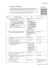
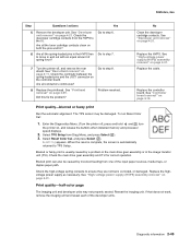
...debris. Step Questions / actions Yes No 1 Measure the distance between bands either 34.6 or 94.2 mm? See "Imaging unit (IU) removal" on page 4-35. 2-46 Service Manual Replace the ITU. Remove and inspect the imaging unit. 5025-2xx, 4xx Print quality-horizontal banding Print the Print Defect Page: 1. At the Ready prompt...Go to step 3. 3 Does the distance measure 37.7, 55, or 78.5 mm? 4 Does the distance measure 43.9 mm or 45.5? See "Image transfer unit (ITU) removal" on page 4-33. Print quality-horizontal line Either the photoconductor unit or one of the imaging unit.
...debris. Step Questions / actions Yes No 1 Measure the distance between bands either 34.6 or 94.2 mm? See "Imaging unit (IU) removal" on page 4-35. 2-46 Service Manual Replace the ITU. Remove and inspect the imaging unit. 5025-2xx, 4xx Print quality-horizontal banding Print the Print Defect Page: 1. At the Ready prompt...Go to step 3. 3 Does the distance measure 37.7, 55, or 78.5 mm? 4 Does the distance measure 43.9 mm or 45.5? See "Image transfer unit (ITU) removal" on page 4-33. Print quality-horizontal line Either the photoconductor unit or one of the imaging unit.
Service Manual
Page 82
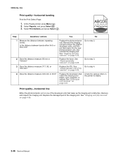
... 4-35. Print quality-random marks Service tip: The primary cause of support. 2-48 Service Manual See "Imaging unit (IU) removal" on the transfer belt? Replace the image transfer unit. See "Image transfer unit (ITU) removal" on page 4-35. Yes Problem resolved. Go to the photoconductor unit, developer roll, or transfer belt. See "Imaging...
... 4-35. Print quality-random marks Service tip: The primary cause of support. 2-48 Service Manual See "Imaging unit (IU) removal" on the transfer belt? Replace the image transfer unit. See "Image transfer unit (ITU) removal" on page 4-35. Yes Problem resolved. Go to the photoconductor unit, developer roll, or transfer belt. See "Imaging...
Service Manual
Page 87
...board without disconnecting it. Check the three spring-loaded contacts between the HVPS and the ITU located at the right rear of the printer and above the HVPS. See "Image transfer unit (ITU) removal" on page 4-31. Yes Go to step 3. Go to step 2. See ... information 2-53 5025-2xx, 4xx Transfer roll service check Step Questions / actions Yes No 1 Turn the printer off , and remove the ITU. Replace the ITU. Insert the tray. See "Image transfer unit (ITU) removal" on page 4-11. Replace the tray 1 sensor. Verify the following values: JHVPS1 Pin Value 7 +3.3 V dc 11 ...
...board without disconnecting it. Check the three spring-loaded contacts between the HVPS and the ITU located at the right rear of the printer and above the HVPS. See "Image transfer unit (ITU) removal" on page 4-31. Yes Go to step 3. Go to step 2. See ... information 2-53 5025-2xx, 4xx Transfer roll service check Step Questions / actions Yes No 1 Turn the printer off , and remove the ITU. Replace the ITU. Insert the tray. See "Image transfer unit (ITU) removal" on page 4-11. Replace the tray 1 sensor. Verify the following values: JHVPS1 Pin Value 7 +3.3 V dc 11 ...
Service Manual
Page 171
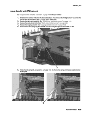
See "Right cover assembly removal" on page 4-60. 4. Remove the waste toner bottle. See "Waste toner bottle removal" on page 4-10. 3. Write down the number of the ITU path. Remove the right cover assembly. Rotate the left spring (B), and pivot the cam away from the side frames, ...the part number. 1. Remove the imaging unit (IU). Disconnect the two springs (A) from the ITU so the spring and the cam are held out of the new ITU before installing it is easier to the ITU. 6. 5025-2xx, 4xx Image transfer unit (ITU) removal See "Image transfer unit (ITU) assembly" on page 4-...
See "Right cover assembly removal" on page 4-60. 4. Remove the waste toner bottle. See "Waste toner bottle removal" on page 4-10. 3. Write down the number of the ITU path. Remove the right cover assembly. Rotate the left spring (B), and pivot the cam away from the side frames, ...the part number. 1. Remove the imaging unit (IU). Disconnect the two springs (A) from the ITU so the spring and the cam are held out of the new ITU before installing it is easier to the ITU. 6. 5025-2xx, 4xx Image transfer unit (ITU) removal See "Image transfer unit (ITU) assembly" on page 4-...
Service Manual
Page 191
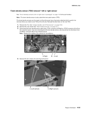
... connector (A Right) or JTDS2 connector (A Left) on the controller board. Repair information 4-53 Remove the rear shield. Note: Observe the routing of the cable(s) for the part number. Remove the ITU. Remove the two screws (C) securing each sensor. The toner density sensors are the same, but the ...left sensor has a thermistor attached which needs to be removed when you are removing the left side. If you install a new TDS ...
... connector (A Right) or JTDS2 connector (A Left) on the controller board. Repair information 4-53 Remove the rear shield. Note: Observe the routing of the cable(s) for the part number. Remove the ITU. Remove the two screws (C) securing each sensor. The toner density sensors are the same, but the ...left sensor has a thermistor attached which needs to be removed when you are removing the left side. If you install a new TDS ...
Service Manual
Page 230
...Motor Detect 3-16 Print Tests input source tests 3-10 Prt Quality Pgs 3-11 Printer Setup Configuration ID 3-18 Defaults 3-17 Engine Setting 1-4 3-18 ITU Barcode 3-19 Model Name 3-18 Page Counts 3-17 Serial Number 3-18 Registration 3-4 Bottom Margin 3-4 Left Margin 3-4 Quick Test 3-5 Right Margin ...menu 3-25 diagnostics mode 3-21 exit deflector parts catalog 7-4 removal 4-24 F Factory Defaults 3-26 fan, service check 2-25 Flash Test 3-17 Font Sharpening 3-27 frame, lower left removal 4-39 right removal 4-41 fuser assembly parts catalog 7-4 removal 4-26 Reset Fuser Cnt 3-19 service check 2-24, 2-...
...Motor Detect 3-16 Print Tests input source tests 3-10 Prt Quality Pgs 3-11 Printer Setup Configuration ID 3-18 Defaults 3-17 Engine Setting 1-4 3-18 ITU Barcode 3-19 Model Name 3-18 Page Counts 3-17 Serial Number 3-18 Registration 3-4 Bottom Margin 3-4 Left Margin 3-4 Quick Test 3-5 Right Margin ...menu 3-25 diagnostics mode 3-21 exit deflector parts catalog 7-4 removal 4-24 F Factory Defaults 3-26 fan, service check 2-25 Flash Test 3-17 Font Sharpening 3-27 frame, lower left removal 4-39 right removal 4-41 fuser assembly parts catalog 7-4 removal 4-26 Reset Fuser Cnt 3-19 service check 2-24, 2-...
Service Manual
Page 232
...Count 3-17 Prt Mono Pg Count 3-17 Prt Quality Pgs configuration menu 3-24 diagnostic menu 3-11 Q quick test duplex 3-13 single-page 3-5 R removals autocompensator mechanism (ACM) 4-15 bin full sensor 4-18 bin full sensor flag 4-24 controller board 4-19 covers front cover assembly 4-2 left cover assembly ...fuser assembly 4-26 fuser drive motor assembly 4-29 fuser exit sensor 4-30 getting started 4-2 high-voltage power supply (HVPS) 4-31 image transfer unit (ITU) 4-33 imaging unit (IU) 4-35 left lower frame 4-39 low-voltage power supply (LVPS) 4-37 main drive gear assembly 4-45 photoconductor unit...
...Count 3-17 Prt Mono Pg Count 3-17 Prt Quality Pgs configuration menu 3-24 diagnostic menu 3-11 Q quick test duplex 3-13 single-page 3-5 R removals autocompensator mechanism (ACM) 4-15 bin full sensor 4-18 bin full sensor flag 4-24 controller board 4-19 covers front cover assembly 4-2 left cover assembly ...fuser assembly 4-26 fuser drive motor assembly 4-29 fuser exit sensor 4-30 getting started 4-2 high-voltage power supply (HVPS) 4-31 image transfer unit (ITU) 4-33 imaging unit (IU) 4-35 left lower frame 4-39 low-voltage power supply (LVPS) 4-37 main drive gear assembly 4-45 photoconductor unit...


