
Hardware Maintenance Manual
Page 5
...19 Passwords 20 Power management 22 Checkout guide 24 Testing the computer 24 Detecting system information with PC-Doctor . . 26 Power system checkout 26 Lenovo 3000 V100 and V200 . . . . . 29 Product overview 30 Specifications 30 Status indicators 33 FRU tests 34 Fn key combinations 35 Symptom-to-FRU index 36... problems 41 Undetermined problems 41 FRU replacement notices 42 Screw notices 42 Retaining serial numbers 42 Removing and replacing a FRU 45 1010 Battery pack 46 1020 Hard disk drive slot cover and hard disk drive 47 1030 DIMM slot cover 49 1040 DIMM 49 1050 Backup...
...19 Passwords 20 Power management 22 Checkout guide 24 Testing the computer 24 Detecting system information with PC-Doctor . . 26 Power system checkout 26 Lenovo 3000 V100 and V200 . . . . . 29 Product overview 30 Specifications 30 Status indicators 33 FRU tests 34 Fn key combinations 35 Symptom-to-FRU index 36... problems 41 Undetermined problems 41 FRU replacement notices 42 Screw notices 42 Retaining serial numbers 42 Removing and replacing a FRU 45 1010 Battery pack 46 1020 Hard disk drive slot cover and hard disk drive 47 1030 DIMM slot cover 49 1040 DIMM 49 1050 Backup...

Hardware Maintenance Manual
Page 20
... on your clothing. Attach the ESD ground clip to electrostatic discharge (ESD.) ESD damage can use coax or connector-outside shells on a double-insulated or battery-operated system, use have been certified (ISO 9000) as those listed below, to provide a static-free work surface. The mat is required for operator safety...
... on your clothing. Attach the ESD ground clip to electrostatic discharge (ESD.) ESD damage can use coax or connector-outside shells on a double-insulated or battery-operated system, use have been certified (ISO 9000) as those listed below, to provide a static-free work surface. The mat is required for operator safety...
Hardware Maintenance Manual
Page 27
... by the servicer: 1. The computer restarts, and the BIOS Setup Utility screen opens. 4. Press F10. General descriptions 21 Remove the battery pack. then, while the initial screen is displayed. 3. Type the current SVP in the Setup confirmation window, select Yes . Then ...battery and the battery pack. (B) If an SVP is selected and the user HDP has been forgotten and cannot be replaced for a scheduled fee. Turn on the computer and wait until the POST ends. Click Yes. Select Password. 6. Note: For some models, the BIOS menu marked *1 is displayed, press the Lenovo...
... by the servicer: 1. The computer restarts, and the BIOS Setup Utility screen opens. 4. Press F10. General descriptions 21 Remove the battery pack. then, while the initial screen is displayed. 3. Type the current SVP in the Setup confirmation window, select Yes . Then ...battery and the battery pack. (B) If an SVP is selected and the user HDP has been forgotten and cannot be replaced for a scheduled fee. Turn on the computer and wait until the POST ends. Click Yes. Select Password. 6. Note: For some models, the BIOS menu marked *1 is displayed, press the Lenovo...
Hardware Maintenance Manual
Page 28
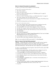
.... In certain circumstances, the computer goes into hibernation mode.) To cause the computer to what occurs in the Setup Configuration window. v If the battery indicator blinks orange, indicating that time. v Open the LCD cover. Note: The computer does not accept any operation with the keyboard, the hard... disk, the parallel connector, or the diskette drive within that the battery power is powered off. v The hard disk drive is powered off . To enter sleep (standby) mode, press Fn+F4. Select Yes in...
.... In certain circumstances, the computer goes into hibernation mode.) To cause the computer to what occurs in the Setup Configuration window. v If the battery indicator blinks orange, indicating that time. v Open the LCD cover. Note: The computer does not accept any operation with the keyboard, the hard... disk, the parallel connector, or the diskette drive within that the battery power is powered off. v The hard disk drive is powered off . To enter sleep (standby) mode, press Fn+F4. Select Yes in...
Hardware Maintenance Manual
Page 32
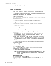
...VESA LCD Info v Hardware Events Log Utility v Run External Tests v Surface Scan Hard Disk v Benchmark System v DOS Shell v Tech Support Form v Battery Rundown v View Test Log v Print Log v Save Log v Full Erase Hard Drive v Quick Erase Hard Drive PC-Doctor for Windows This product ...is supplied when you troubleshoot and resolve problems related to display symptoms and solutions: v CHECK SYSTEM HEALTH v SYSTEM AND DEVICE TESTS v LENOVO TROUBLESHOOTING v CENTER v SYSTEM REPORTS v UPDATES AND SUPPORT Power system checkout To verify a symptom, do the following: 1. Connect the ac ...
...VESA LCD Info v Hardware Events Log Utility v Run External Tests v Surface Scan Hard Disk v Benchmark System v DOS Shell v Tech Support Form v Battery Rundown v View Test Log v Print Log v Save Log v Full Erase Hard Drive v Quick Erase Hard Drive PC-Doctor for Windows This product ...is supplied when you troubleshoot and resolve problems related to display symptoms and solutions: v CHECK SYSTEM HEALTH v SYSTEM AND DEVICE TESTS v LENOVO TROUBLESHOOTING v CENTER v SYSTEM REPORTS v UPDATES AND SUPPORT Power system checkout To verify a symptom, do the following: 1. Connect the ac ...

Hardware Maintenance Manual
Page 33
...taskbar and wait for correct continuity and installation. Then reinstall the battery pack. under this condition the battery pack can charge to "Product overview" on , replace the battery pack. Reinstall the battery pack. If it return to the next section. General descriptions 27...Replace the system board. If the charge indicator still does not turn on , replace the system board. To get detailed information about the battery, double-click the Power Meter icon. Checkout guide Checking the ac adapter You are servicing. 3. Perform operational charging. See the following figure...
...taskbar and wait for correct continuity and installation. Then reinstall the battery pack. under this condition the battery pack can charge to "Product overview" on , replace the battery pack. Reinstall the battery pack. If it return to the next section. General descriptions 27...Replace the system board. If the charge indicator still does not turn on , replace the system board. To get detailed information about the battery, double-click the Power Meter icon. Checkout guide Checking the ac adapter You are servicing. 3. Perform operational charging. See the following figure...

Hardware Maintenance Manual
Page 34
.... Power off the computer. 2. The resistance must be able to charge. Remove the battery pack and measure the voltage between battery terminals 4 and 7. If the voltage is more than +11.0 V dc after recharging, replace the battery. 4. If the resistance is correct, replace the system board. 28 MT 0763 and... 0764 Note: Recharging will take at room temperature for a while. If the resistance is not correct, replace the battery pack. Checkout guide Note: If the battery pack becomes hot, it may not be 4 to 30 K . Remove it from the computer and leave it . After it ...
.... Power off the computer. 2. The resistance must be able to charge. Remove the battery pack and measure the voltage between battery terminals 4 and 7. If the voltage is more than +11.0 V dc after recharging, replace the battery. 4. If the resistance is correct, replace the system board. 28 MT 0763 and... 0764 Note: Recharging will take at room temperature for a while. If the resistance is not correct, replace the battery pack. Checkout guide Note: If the battery pack becomes hot, it may not be 4 to 30 K . Remove it from the computer and leave it . After it ...

Hardware Maintenance Manual
Page 35
Lenovo 3000 V100 and V200 Product overview 30 Specifications 30 Status indicators 33 FRU tests 34 Fn key combinations 35 Symptom-to-...43 Retaining the UUID 43 Reading or writing the ECA information . . 43 Removing and replacing a FRU 45 1010 Battery pack 46 1020 Hard disk drive slot cover and hard disk drive 47 1030 DIMM slot cover 49 1040 DIMM 49 1050 ...Backup battery 50 1060 PCI Express Mini Card slot cover and PCI Express Mini Card for MT 0764 112 Windows Vista Ultimate (32 ...
Lenovo 3000 V100 and V200 Product overview 30 Specifications 30 Status indicators 33 FRU tests 34 Fn key combinations 35 Symptom-to-...43 Retaining the UUID 43 Reading or writing the ECA information . . 43 Removing and replacing a FRU 45 1010 Battery pack 46 1020 Hard disk drive slot cover and hard disk drive 47 1030 DIMM slot cover 49 1040 DIMM 49 1050 ...Backup battery 50 1060 PCI Express Mini Card slot cover and PCI Express Mini Card for MT 0764 112 Windows Vista Ultimate (32 ...
Hardware Maintenance Manual
Page 38
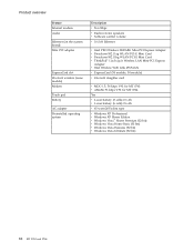
... overview Feature Internal modem Audio Ethernet (on the system board) Mini PCI adapter ExpressCard slot Bluetooth wireless (some models) Modem Touch pad Battery AC adapter Preinstalled operating system Description v 56.6 Kbps v Built-in stereo speakers v Software control volume v 10/100 Ethernet v Intel...54 module) v Bluetooth daughter card v MDC-1.5, 56 kbps V.92 for MT 0763 v AMoM, 56 kbps V.92 for MT 0764 Yes v Li-ion battery (3 cells) 2.6 Ah v Li-ion battery (6 cells) 2.6 Ah v 65-watt (20V) slim type v Windows XP Professional v Windows XP Home Edition v Windows Vista™ Home Premium (...
... overview Feature Internal modem Audio Ethernet (on the system board) Mini PCI adapter ExpressCard slot Bluetooth wireless (some models) Modem Touch pad Battery AC adapter Preinstalled operating system Description v 56.6 Kbps v Built-in stereo speakers v Software control volume v 10/100 Ethernet v Intel...54 module) v Bluetooth daughter card v MDC-1.5, 56 kbps V.92 for MT 0763 v AMoM, 56 kbps V.92 for MT 0764 Yes v Li-ion battery (3 cells) 2.6 Ah v Li-ion battery (6 cells) 2.6 Ah v 65-watt (20V) slim type v Windows XP Professional v Windows XP Home Edition v Windows Vista™ Home Premium (...

Hardware Maintenance Manual
Page 40
... remove one , and run Diagnostics --> Memory Test-Full. 34 MT 0763 and 0764 Blinking green: The battery is ready for each FRU. Orange: The battery is being transmitted. Blinking green: Data is charged between 5% and 20% of the capacity, and being discharged... v Diagnostics --> Diskette Drives 1. FRU tests The following table shows the test for use . Product overview Indicator 7 Battery status 8 Bluetooth status R 9 Wireless status Meaning Green: The battery is charged between 5% to 20% of the capacity, and being charged. Blinking green: Data is being transmitted. Diagnostics...
... remove one , and run Diagnostics --> Memory Test-Full. 34 MT 0763 and 0764 Blinking green: The battery is ready for each FRU. Orange: The battery is being transmitted. Blinking green: Data is charged between 5% and 20% of the capacity, and being discharged... v Diagnostics --> Diskette Drives 1. FRU tests The following table shows the test for use . Product overview Indicator 7 Battery status 8 Bluetooth status R 9 Wireless status Meaning Green: The battery is charged between 5% to 20% of the capacity, and being charged. Blinking green: Data is being transmitted. Diagnostics...
Hardware Maintenance Manual
Page 42
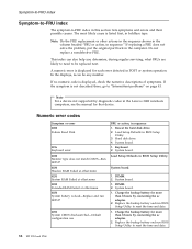
..., put the original part back in sequence." Hard disk drive. 4. System board. 1. System board. 1. Charge the backup battery for more than 8 hours by diagnostic codes in the Lenovo 3000 notebook computers, see the manual for that device. Symptom-to-FRU index Symptom-to-FRU index The symptom-to-FRU...determine, during regular servicing, what FRUs are likely to need to reset the time and date. 36 MT 0763 and 0764 Charge the backup battery for each error detected in sequence 1. If no numeric code is displayed, check the narrative descriptions of symptoms. If the symptom is dead-...
..., put the original part back in sequence." Hard disk drive. 4. System board. 1. System board. 1. Charge the backup battery for more than 8 hours by diagnostic codes in the Lenovo 3000 notebook computers, see the manual for that device. Symptom-to-FRU index Symptom-to-FRU index The symptom-to-FRU...determine, during regular servicing, what FRUs are likely to need to reset the time and date. 36 MT 0763 and 0764 Charge the backup battery for each error detected in sequence 1. If no numeric code is displayed, check the narrative descriptions of symptoms. If the symptom is dead-...

Hardware Maintenance Manual
Page 43
...Previous boot incomplete- Charge the backup battery for more than 8 hours by connecting the ac adapter. 2. DIMM. 3. DIMM. 2. Lenovo 3000 V100 and V200 37 System board. 1. System board. 1. DIMM. 2. System board. Charge the backup battery for more than 8 hours by connecting... the ac adapter. 2. Replace the backup battery and run BIOS Setup Utility to reset the time...
...Previous boot incomplete- Charge the backup battery for more than 8 hours by connecting the ac adapter. 2. DIMM. 3. DIMM. 2. Lenovo 3000 V100 and V200 37 System board. 1. System board. 1. DIMM. 2. System board. Charge the backup battery for more than 8 hours by connecting... the ac adapter. 2. Replace the backup battery and run BIOS Setup Utility to reset the time...

Hardware Maintenance Manual
Page 44
... entered hibernation mode. 2. Device Error. 1. Hibernation error. Authentication of device which you want to boot from . System board. 1. Backup battery. 3. System board. No valid operating system. 1. Excluded from a recovery disc. Load "Setup Defaults" in the BIOS Setup Utility. 2.... operating system has no failure and is corrupted. Allocation error for device. Failing bits: nnnn. Cannot boot from . 2. Backup battery. 3. Backup battery. 3. DIMM. 2. If memory size has been changed, re-create the hibernation file. 1. System board. System board. The...
... entered hibernation mode. 2. Device Error. 1. Hibernation error. Authentication of device which you want to boot from . System board. 1. Backup battery. 3. System board. No valid operating system. 1. Excluded from a recovery disc. Load "Setup Defaults" in the BIOS Setup Utility. 2.... operating system has no failure and is corrupted. Allocation error for device. Failing bits: nnnn. Cannot boot from . 2. Backup battery. 3. Backup battery. 3. DIMM. 2. If memory size has been changed, re-create the hibernation file. 1. System board. System board. The...

Hardware Maintenance Manual
Page 47
...4. If the problem does not recur, reconnect the removed devices one at a time until you find the failing FRU. 7. LCD assembly Lenovo 3000 V100 and V200 41 Run the diagnostic test for damage. Turn off the computer. 2. DIMM h. Determine whether the problem has been solved. 6. If ...check each FRU for the system board in the internal drive i. Replace any FRUs. 3. Non-Lenovo 3000 devices b. Devices attached to isolate the failing FRU (do the following devices: a. Battery pack e. Hard disk drive f. External diskette drive or optical drive g. Optical disk or diskette in...
...4. If the problem does not recur, reconnect the removed devices one at a time until you find the failing FRU. 7. LCD assembly Lenovo 3000 V100 and V200 41 Run the diagnostic test for damage. Turn off the computer. 2. DIMM h. Determine whether the problem has been solved. 6. If ...check each FRU for the system board in the internal drive i. Replace any FRUs. 3. Non-Lenovo 3000 devices b. Devices attached to isolate the failing FRU (do the following devices: a. Battery pack e. Hard disk drive f. External diskette drive or optical drive g. Optical disk or diskette in...
Hardware Maintenance Manual
Page 51
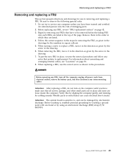
...given by the arrow in place, reverse the removal procedure and follow any FRUs that all power cords from electrical outlets, remove the battery pack, and then disconnect any computer unless you have been trained and certified. For information about connecting and arranging internal cables, see "...a FRU, turn it , establish personal grounding by touching a ground point with one hand or by the arrow in square callouts. 5. Lenovo 3000 V100 and V200 45 Attention: After replacing a FRU, do not turn off the computer, unplug all screws, springs, and other small parts are in removing...
...given by the arrow in place, reverse the removal procedure and follow any FRUs that all power cords from electrical outlets, remove the battery pack, and then disconnect any computer unless you have been trained and certified. For information about connecting and arranging internal cables, see "...a FRU, turn it , establish personal grounding by touching a ground point with one hand or by the arrow in square callouts. 5. Lenovo 3000 V100 and V200 45 Attention: After replacing a FRU, do not turn off the computer, unplug all screws, springs, and other small parts are in removing...

Hardware Maintenance Manual
Page 52
Removing and replacing a FRU 1010 Battery pack DANGER Use only the battery specified in the direction shown by arrow 3. 2 1 3 46 MT 0763 and 0764 Unlock the battery release lever 1 and holding the battery release lever in the unlocked position 2 , remove the battery pack in the parts list for your computer. Any other battery could ignite or explode.
Removing and replacing a FRU 1010 Battery pack DANGER Use only the battery specified in the direction shown by arrow 3. 2 1 3 46 MT 0763 and 0764 Unlock the battery release lever 1 and holding the battery release lever in the unlocked position 2 , remove the battery pack in the parts list for your computer. Any other battery could ignite or explode.

Hardware Maintenance Manual
Page 53
... drive slot cover and hard disk drive For access, remove this FRU: v "1010 Battery pack" on it . The hard disk drive is in suspend mode. Note: Loosen the screws 1 , but do not remove them. 2 1 (continued) Lenovo 3000 V100 and V200 47 v Before removing the drive, have the user make a backup copy of data...
... drive slot cover and hard disk drive For access, remove this FRU: v "1010 Battery pack" on it . The hard disk drive is in suspend mode. Note: Loosen the screws 1 , but do not remove them. 2 1 (continued) Lenovo 3000 V100 and V200 47 v Before removing the drive, have the user make a backup copy of data...

Hardware Maintenance Manual
Page 55
Press the DIMM firmly, and pivot it until it is firmly fixed in order: v "1010 Battery pack" on page 46 v "1030 DIMM slot cover" 1 2 1 When installing: Insert the notched end of the DIMM into the place. Lenovo 3000 V100 and V200 49 Make sure that it snaps into the socket. Removing and replacing a FRU 1030 DIMM slot cover For access, remove this FRU: v "1010 Battery pack" on page 46 Note: Loosen the screws 1 , but do not remove them. 2 1 1040 DIMM For access, remove these FRUs in the slot and does not move easily.
Press the DIMM firmly, and pivot it until it is firmly fixed in order: v "1010 Battery pack" on page 46 v "1030 DIMM slot cover" 1 2 1 When installing: Insert the notched end of the DIMM into the place. Lenovo 3000 V100 and V200 49 Make sure that it snaps into the socket. Removing and replacing a FRU 1030 DIMM slot cover For access, remove this FRU: v "1010 Battery pack" on page 46 Note: Loosen the screws 1 , but do not remove them. 2 1 1040 DIMM For access, remove these FRUs in the slot and does not move easily.

Hardware Maintenance Manual
Page 56
For access, remove these FRUs in the parts list for your computer. Any other battery could ignite or explode. Removing and replacing a FRU 1050 Backup battery DANGER Use only the battery specified in order: v "1010 Battery pack" on page 46 v "1030 DIMM slot cover" on page 49 1 2 When installing: Make sure that the battery connector is attached firmly. 50 MT 0763 and 0764
For access, remove these FRUs in the parts list for your computer. Any other battery could ignite or explode. Removing and replacing a FRU 1050 Backup battery DANGER Use only the battery specified in order: v "1010 Battery pack" on page 46 v "1030 DIMM slot cover" on page 49 1 2 When installing: Make sure that the battery connector is attached firmly. 50 MT 0763 and 0764

Hardware Maintenance Manual
Page 57
... PCI Express Mini Card slot cover and PCI Express Mini Card for 802.11 a/b/g wireless LAN For access, remove these FRUs in order: v "1010 Battery pack" on the card, and the black cable into the jack labeled MAIN on page 46 Note: Loosen the screws 1 , but do not remove ... using the removal tool antenna RF connector (P/N: 08K7159) or pick the connectors with your fingers and gently unplug them in direction of the arrow. Lenovo 3000 V100 and V200 51 Step 4 Screw (quantity) M2 × 4 mm, pan-head, nylon-coated (2) Color Silver Torque 0.245 Nm (2.5 kgfcm) When installing: Plug the gray...
... PCI Express Mini Card slot cover and PCI Express Mini Card for 802.11 a/b/g wireless LAN For access, remove these FRUs in order: v "1010 Battery pack" on the card, and the black cable into the jack labeled MAIN on page 46 Note: Loosen the screws 1 , but do not remove ... using the removal tool antenna RF connector (P/N: 08K7159) or pick the connectors with your fingers and gently unplug them in direction of the arrow. Lenovo 3000 V100 and V200 51 Step 4 Screw (quantity) M2 × 4 mm, pan-head, nylon-coated (2) Color Silver Torque 0.245 Nm (2.5 kgfcm) When installing: Plug the gray...


