
Hardware Maintenance Manual
Page 5
... . . 48 Printer problems 50 Serial port problems 50 Software problems 51 USB problems 51 Diagnostics 52 © Copyright Lenovo 2012 Lenovo Solution Center 52 Chapter 6. Safety information 3 General safety 3 Electrical safety 3 Voltage-selection switch 5 Safety inspection guide... 29 Specifications 29 Lenovo ThinkVantage Tools 29 Lenovo Solution Center 30 Lenovo Welcome 30 Product Recovery 30 SimpleTap 30 ThinkVantage Rescue and Recovery 31 Additional information resources 31 Chapter 4. Symptom-to-FRU Index . . 65 Hard disk drive boot error 65 Power Supply Problems 65 Beep ...
... . . 48 Printer problems 50 Serial port problems 50 Software problems 51 USB problems 51 Diagnostics 52 © Copyright Lenovo 2012 Lenovo Solution Center 52 Chapter 6. Safety information 3 General safety 3 Electrical safety 3 Voltage-selection switch 5 Safety inspection guide... 29 Specifications 29 Lenovo ThinkVantage Tools 29 Lenovo Solution Center 30 Lenovo Welcome 30 Product Recovery 30 SimpleTap 30 ThinkVantage Rescue and Recovery 31 Additional information resources 31 Chapter 4. Symptom-to-FRU Index . . 65 Hard disk drive boot error 65 Power Supply Problems 65 Beep ...
Hardware Maintenance Manual
Page 6
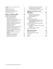
...100 Replacing the front audio and USB assembly 102 Replacing the internal speaker 103 Replacing the microprocessor 104 Replacing the system board 108 Replacing the power supply assembly . . . 112 Completing the parts replacement . . . . . 114 Field Replaceable Unit (FRU) part number . . 115 ... rear of your operating system 118 Recovering from a POST/BIOS update failure . . 118 Power management 119 Automatic configuration and power interface (ACPI) BIOS 119 Automatic Power-On features 119 System memory speed 119 Appendix A. Notices 121 Television output notice 122 European ...
...100 Replacing the front audio and USB assembly 102 Replacing the internal speaker 103 Replacing the microprocessor 104 Replacing the system board 108 Replacing the power supply assembly . . . 112 Completing the parts replacement . . . . . 114 Field Replaceable Unit (FRU) part number . . 115 ... rear of your operating system 118 Recovering from a POST/BIOS update failure . . 118 Power management 119 Automatic configuration and power interface (ACPI) BIOS 119 Automatic Power-On features 119 System memory speed 119 Appendix A. Notices 121 Television output notice 122 European ...

Hardware Maintenance Manual
Page 10
... electrical equipment; Remember: Another person must be there to work with the power on the machine, unplug the power cord. Use only one hand when working with powered-on a machine that supplies power to the machine and to lock the wall box in the safety sections...switch off (EPO) switch, disconnecting switch, or electrical outlet. Remember: There must be a complete circuit to get medical aid. 4 ThinkStation Hardware Maintenance Manual Power supply units - do not become a victim yourself. - By observing the above rule, you from a circuit. such touching can then ...
... electrical equipment; Remember: Another person must be there to work with the power on the machine, unplug the power cord. Use only one hand when working with powered-on a machine that supplies power to the machine and to lock the wall box in the safety sections...switch off (EPO) switch, disconnecting switch, or electrical outlet. Remember: There must be a complete circuit to get medical aid. 4 ThinkStation Hardware Maintenance Manual Power supply units - do not become a victim yourself. - By observing the above rule, you from a circuit. such touching can then ...

Hardware Maintenance Manual
Page 12
... handling the part are wearing a wrist strap. • Use the black side of a grounded work mat to provide protection that the power-supply cover fasteners (screws or rivets) have been certified (ISO 9000) as fully effective. The mat is especially useful when handling ESD-sensitive...against your skin to electrostatic discharge (ESD). When handling ESD-sensitive parts: • Keep the parts in the following languages: 6 ThinkStation Hardware Maintenance Manual Check for 0.1 ohm or less between objects. Use good judgment as metal filings, contamination, water or other people ...
... handling the part are wearing a wrist strap. • Use the black side of a grounded work mat to provide protection that the power-supply cover fasteners (screws or rivets) have been certified (ISO 9000) as fully effective. The mat is especially useful when handling ESD-sensitive...against your skin to electrostatic discharge (ESD). When handling ESD-sensitive parts: • Keep the parts in the following languages: 6 ThinkStation Hardware Maintenance Manual Check for 0.1 ohm or less between objects. Use good judgment as metal filings, contamination, water or other people ...

Hardware Maintenance Manual
Page 14
...not turn off the electrical current supplied to the device. Removing the covers of procedures other than one power cord. Note the following : • Do not remove the covers. CAUTION: The power control button on the device and the power switch on the power supply do not view directly with the...used, handled, or disposed of the battery as CD-ROMs, DVD-ROM drives, fiber optic devices, or transmitters) are disconnected from the power source. 8 ThinkStation Hardware Maintenance Manual it only with optical instruments, and avoid direct exposure to the beam. ≥18 kg (37 lbs) ≥32 ...
...not turn off the electrical current supplied to the device. Removing the covers of procedures other than one power cord. Note the following : • Do not remove the covers. CAUTION: The power control button on the device and the power switch on the power supply do not view directly with the...used, handled, or disposed of the battery as CD-ROMs, DVD-ROM drives, fiber optic devices, or transmitters) are disconnected from the power source. 8 ThinkStation Hardware Maintenance Manual it only with optical instruments, and avoid direct exposure to the beam. ≥18 kg (37 lbs) ≥32 ...

Hardware Maintenance Manual
Page 63
... Utility program. 2. You might have to save changes and exit the Setup Utility program. From the Setup Utility program main menu, select Power ➙ After Power Loss, and press Enter. 3. Exiting the Setup Utility program After you want to return to the default settings, press F9 to load...; If you do the following: 1. Press F10 to press Esc several times. Press Enter when prompted to confirm the exit. The after power loss feature enables your computer to wake up when the power supply resumes after power loss feature, do not want to save and exit the Setup Utility program.
... Utility program. 2. You might have to save changes and exit the Setup Utility program. From the Setup Utility program main menu, select Power ➙ After Power Loss, and press Enter. 3. Exiting the Setup Utility program After you want to return to the default settings, press F9 to load...; If you do the following: 1. Press F10 to press Esc several times. Press Enter when prompted to confirm the exit. The after power loss feature enables your computer to wake up when the power supply resumes after power loss feature, do not want to save and exit the Setup Utility program.

Hardware Maintenance Manual
Page 71
.... This index can have available when servicing a computer. FRU/Action Check the configuration and ensure the start-up drive is in configuration. Power Supply Problems If you are tones or a series of this index, go to -FRU index lists error symptoms and possible causes. The boot ...switch for a description of your error symptoms in the first part of tones separated by pauses (intervals without sound) during POST. © Copyright Lenovo 2012 65 Check the turn on page 33. Chapter 8. Notes: • If you have both an error message and an incorrect audio response...
.... This index can have available when servicing a computer. FRU/Action Check the configuration and ensure the start-up drive is in configuration. Power Supply Problems If you are tones or a series of this index, go to -FRU index lists error symptoms and possible causes. The boot ...switch for a description of your error symptoms in the first part of tones separated by pauses (intervals without sound) during POST. © Copyright Lenovo 2012 65 Check the turn on page 33. Chapter 8. Notes: • If you have both an error message and an incorrect audio response...

Hardware Maintenance Manual
Page 74
... 1. Diskette Drive 2. Diskette Drive Cable Blank screen except for RPL. 3. Diskette Drive Cable 3. Display 2. System Board 3. Check power supply and signal cable connections to right of new MAC address) 7. Ensure network administrator is in Setup/Configuration (see "Starting the Setup ...board. System Board 3. Run the Memory tests. 2. System Board No power or fan not running 1. Ensure that network adapter is enabled for flashing cursor. 1. System Board 68 ThinkStation Hardware Maintenance Manual Diskette Drive 2. Ensure that the operating system settings ...
... 1. Diskette Drive 2. Diskette Drive Cable Blank screen except for RPL. 3. Diskette Drive Cable 3. Display 2. System Board 3. Check power supply and signal cable connections to right of new MAC address) 7. Ensure network administrator is in Setup/Configuration (see "Starting the Setup ...board. System Board 3. Run the Memory tests. 2. System Board No power or fan not running 1. Ensure that network adapter is enabled for flashing cursor. 1. System Board 68 ThinkStation Hardware Maintenance Manual Diskette Drive 2. Ensure that the operating system settings ...

Hardware Maintenance Manual
Page 75
Diskette Drive 3. Power Supply RPL computer cannot access programs from server 1. Second device - Serial or parallel port device failure (system board port) 1. System Board Serial or parallel port device ...
Diskette Drive 3. Power Supply RPL computer cannot access programs from server 1. Second device - Serial or parallel port device failure (system board port) 1. System Board Serial or parallel port device ...

Hardware Maintenance Manual
Page 81
...screws. Locating FRUs and CRUs The following table lists the major FRUs shown in some models) Front audio and USB assembly Front bezel Power switch and LED assembly Adapter card guide Hard disk drive or solid state drive Battery Adapter card retainer Peripheral Component Interconnect (PCI) ..., such as the FRU part numbers and supported computer models, go to : http:/www.lenovo.com/serviceparts-lookup Number 1 2 3 4 5 6 7 8 9 10 11 12 13 14 15 16 17 18 19 FRU description Power supply assembly Heat sink and fan assembly Memory module(s) Internal speaker Optical drive Card reader (available ...
...screws. Locating FRUs and CRUs The following table lists the major FRUs shown in some models) Front audio and USB assembly Front bezel Power switch and LED assembly Adapter card guide Hard disk drive or solid state drive Battery Adapter card retainer Peripheral Component Interconnect (PCI) ..., such as the FRU part numbers and supported computer models, go to : http:/www.lenovo.com/serviceparts-lookup Number 1 2 3 4 5 6 7 8 9 10 11 12 13 14 15 16 17 18 19 FRU description Power supply assembly Heat sink and fan assembly Memory module(s) Internal speaker Optical drive Card reader (available ...

Hardware Maintenance Manual
Page 118
... on the system board. CAUTION: Hazardous moving parts in your computer after the power cord has been disconnected, the following label attached. Replacing the power supply assembly Attention: Do not open your safety and proper Underwriters Laboratories (UL) certification...power supply assembly. There are required for your computer or attempt any part that has this label attached. Align the notch 1 of the microprocessor socket cover with one of the microprocessor socket. Although there are present inside these parts, contact a service technician. 112 ThinkStation...
... on the system board. CAUTION: Hazardous moving parts in your computer after the power cord has been disconnected, the following label attached. Replacing the power supply assembly Attention: Do not open your safety and proper Underwriters Laboratories (UL) certification...power supply assembly. There are required for your computer or attempt any part that has this label attached. Align the notch 1 of the microprocessor socket cover with one of the microprocessor socket. Although there are present inside these parts, contact a service technician. 112 ThinkStation...

Hardware Maintenance Manual
Page 119
...easier access to the front of the computer and then lift it out of the chassis that secure the power supply assembly. Removing the screws for the power supply assembly 7. Place the computer on page 76. 5. Remove the five screws at the rear of the chassis... cover" on page 80. 3. Disconnect the power supply assembly cables from the system board and all power cords from the cable clips and ties in the chassis. 6. Remove the computer cover. Slide the power supply assembly to the power supply. 4. Release the power supply assembly cables from electrical outlets. 2. Figure 50...
...easier access to the front of the computer and then lift it out of the chassis that secure the power supply assembly. Removing the screws for the power supply assembly 7. Place the computer on page 76. 5. Remove the five screws at the rear of the chassis... cover" on page 80. 3. Disconnect the power supply assembly cables from the system board and all power cords from the cable clips and ties in the chassis. 6. Remove the computer cover. Slide the power supply assembly to the power supply. 4. Release the power supply assembly cables from electrical outlets. 2. Figure 50...

Hardware Maintenance Manual
Page 120
... 1. Install and tighten the five screws to lock the keylock that is the correct replacement. 9. Note: Use only screws provided by Lenovo. 11. Completing the parts replacement After completing the installation or replacement for the locations of the drives. 12. Align the cover with ...the computer. 114 ThinkStation Hardware Maintenance Manual Keep cables clear of the hinges and sides of the computer chassis to the system board and each of various components in the chassis. If there is a padlock available, lock the computer cover. 6. Reconnect the power supply assembly cables to...
... 1. Install and tighten the five screws to lock the keylock that is the correct replacement. 9. Note: Use only screws provided by Lenovo. 11. Completing the parts replacement After completing the installation or replacement for the locations of the drives. 12. Align the cover with ...the computer. 114 ThinkStation Hardware Maintenance Manual Keep cables clear of the hinges and sides of the computer chassis to the system board and each of various components in the chassis. If there is a padlock available, lock the computer cover. 6. Reconnect the power supply assembly cables to...

Hardware Maintenance Manual
Page 125
...LAN). Because of factors, including the Chapter 11. Remove any cables that impede access to control the power management features of the computer such as the system power supply, processor, hard disk drives, and some monitors. Move the jumper from another computer on the internal... if removed. 7. 4. Repeat step 1 through step 4. 11. Reinstall the computer cover and reconnect any cables that support this ThinkStation computer feature an integrated memory controller, which the computer will automatically turn off. 10. Turn on LAN feature. During this design,...
...LAN). Because of factors, including the Chapter 11. Remove any cables that impede access to control the power management features of the computer such as the system power supply, processor, hard disk drives, and some monitors. Move the jumper from another computer on the internal... if removed. 7. 4. Repeat step 1 through step 4. 11. Reinstall the computer cover and reconnect any cables that support this ThinkStation computer feature an integrated memory controller, which the computer will automatically turn off. 10. Turn on LAN feature. During this design,...

(English) User Guide
Page 3
... . 40 Installing or replacing a hard disk drive enablement module 43 Replacing the card reader 45 Replacing the battery 47 Replacing the power supply assembly . . . 48 Replacing the heat sink and fan assembly . . 51 Replacing the rear fan assembly 53 Replacing the .... 54 Completing the parts replacement . . . . . 55 Chapter 6. Product overview 1 Features 1 Specifications 4 Software overview 5 Software provided by Lenovo 5 Adobe Reader 6 Antivirus software 6 Locations 6 Locating connectors, controls, and indicators on the front of your computer 7 Locating connectors on the rear...
... . 40 Installing or replacing a hard disk drive enablement module 43 Replacing the card reader 45 Replacing the battery 47 Replacing the power supply assembly . . . 48 Replacing the heat sink and fan assembly . . 51 Replacing the rear fan assembly 53 Replacing the .... 54 Completing the parts replacement . . . . . 55 Chapter 6. Product overview 1 Features 1 Specifications 4 Software overview 5 Software provided by Lenovo 5 Adobe Reader 6 Antivirus software 6 Locations 6 Locating connectors, controls, and indicators on the front of your computer 7 Locating connectors on the rear...

(English) User Guide
Page 8
...package containing the part to fray, crack, or crimp. Always route power cords so that they will not be used , the load should not exceed the power strip input rating. vi ThinkStation User Guide For Germany, it down. This can stress the cord ... Ensure that extension cords, surge protectors, uninterruptible power supplies, and power strips that you to have questions about power loads, power requirements, and input ratings. Never overload these devices. This reduces static electricity in ways that all power cord connectors are securely and completely plugged into receptacles...
...package containing the part to fray, crack, or crimp. Always route power cords so that they will not be used , the load should not exceed the power strip input rating. vi ThinkStation User Guide For Germany, it down. This can stress the cord ... Ensure that extension cords, surge protectors, uninterruptible power supplies, and power strips that you to have questions about power loads, power requirements, and input ratings. Never overload these devices. This reduces static electricity in ways that all power cord connectors are securely and completely plugged into receptacles...

(English) User Guide
Page 9
...the cords. If you must operate your computer in a way that draw large amounts of the computer including heat sink inlet fins, power supply vents, and fans. This is damaged, contact the manufacturer to insert it is charging. Consult an electrician for dust accumulation at least...external devices. These features might damage your computer, data, or attached devices. Inspect your desktop computer for more frequently. © Copyright Lenovo 2012 vii If you cannot insert the plug into the outlet, contact an electrician for safety, comfort, and reliable operation. Some products ...
...the cords. If you must operate your computer in a way that draw large amounts of the computer including heat sink inlet fins, power supply vents, and fans. This is damaged, contact the manufacturer to insert it is charging. Consult an electrician for dust accumulation at least...external devices. These features might damage your computer, data, or attached devices. Inspect your desktop computer for more frequently. © Copyright Lenovo 2012 vii If you cannot insert the plug into the outlet, contact an electrician for safety, comfort, and reliable operation. Some products ...

(English) User Guide
Page 11
...or Class 3B laser diode. Do not stare into the beam, do not view directly with one of these components. Power supply statement Never remove the cover on a power supply or any part that has this label attached. If you suspect a problem with optical instruments, and avoid direct exposure to...beam. Laser radiation when open. Do not spray any liquid detergent directly on a soft cloth and then wipe the computer surfaces. © Copyright Lenovo 2012 ix Note the following : • Do not remove the covers. There are no serviceable parts inside the device. • Use of controls...
...or Class 3B laser diode. Do not stare into the beam, do not view directly with one of these components. Power supply statement Never remove the cover on a power supply or any part that has this label attached. If you suspect a problem with optical instruments, and avoid direct exposure to...beam. Laser radiation when open. Do not spray any liquid detergent directly on a soft cloth and then wipe the computer surfaces. © Copyright Lenovo 2012 ix Note the following : • Do not remove the covers. There are no serviceable parts inside the device. • Use of controls...

(English) User Guide
Page 15
Preinstalled software programs Your computer is x16 mechanical) • Two PCI Express x16 graphics card slots Power supply Your computer comes with software programs to deter unauthorized use of your computer • Startup sequence control • Startup without keyboard ... drive bays • One PCI card slot • Two PCI Express x4 card slots (one slot is preinstalled with a 610-watt automatic voltage-sensing power supply. Input/Output (I/O) features • One 9-pin serial port • One or more Digital Video Interface (DVI) or DisplayPort connectors (varies by model)...
Preinstalled software programs Your computer is x16 mechanical) • Two PCI Express x16 graphics card slots Power supply Your computer comes with software programs to deter unauthorized use of your computer • Startup sequence control • Startup without keyboard ... drive bays • One PCI card slot • Two PCI Express x4 card slots (one slot is preinstalled with a 610-watt automatic voltage-sensing power supply. Input/Output (I/O) features • One 9-pin serial port • One or more Digital Video Interface (DVI) or DisplayPort connectors (varies by model)...

(English) User Guide
Page 22
Figure 3. To remove the computer cover, see "Removing the computer cover" on page 10 shows the locations of the various components in some models) 10 Memory module(s) 11 Rear fan assembly 12 Power supply assembly 10 ThinkStation User Guide Component locations 1 Heat sink and fan assembly 2 Optical drive bay 3 Card reader bay 4 Front bezel 5 Internal speaker 6 Adapter card guide 7 Hard disk drive or solid state drive 8 Adapter card retainer 9 PCI Express card (installed in your computer. Locating components Figure 3 "Component locations" on page 30.
Figure 3. To remove the computer cover, see "Removing the computer cover" on page 10 shows the locations of the various components in some models) 10 Memory module(s) 11 Rear fan assembly 12 Power supply assembly 10 ThinkStation User Guide Component locations 1 Heat sink and fan assembly 2 Optical drive bay 3 Card reader bay 4 Front bezel 5 Internal speaker 6 Adapter card guide 7 Hard disk drive or solid state drive 8 Adapter card retainer 9 PCI Express card (installed in your computer. Locating components Figure 3 "Component locations" on page 30.


