User Manual
Page 5
...51 Advanced settings 51 Exiting from the CD or diskettes . . 45 Navigating through the diagnostics programs . . 45 Running tests 45 Viewing the test log 47 Chapter 6. General information . . . . 39 The ThinkVantage Productivity Center program . . 39 Additional information ... a fan assembly 119 Replacing the internal speaker 120 Replacing the front panel connector assembly . . 121 Completing the FRU replacement 123 © Copyright Lenovo 2006, 2008 iii Safety information . . . . . 3 General safety 3 Electrical safety 3 Voltage-selection switch 5 Safety inspection guide 5 Handling...
...51 Advanced settings 51 Exiting from the CD or diskettes . . 45 Navigating through the diagnostics programs . . 45 Running tests 45 Viewing the test log 47 Chapter 6. General information . . . . 39 The ThinkVantage Productivity Center program . . 39 Additional information ... a fan assembly 119 Replacing the internal speaker 120 Replacing the front panel connector assembly . . 121 Completing the FRU replacement 123 © Copyright Lenovo 2006, 2008 iii Safety information . . . . . 3 General safety 3 Electrical safety 3 Voltage-selection switch 5 Safety inspection guide 5 Handling...

User Manual
Page 10
... equipment, rubber floor mats that power has been disconnected from grounds such as metal floor strips and machine frames. Important: Use only approved tools and test equipment. keep the other hand in the installation and configuration procedures. Do not use worn or broken tools and testers. Remember: Another person must be...
... equipment, rubber floor mats that power has been disconnected from grounds such as metal floor strips and machine frames. Important: Use only approved tools and test equipment. keep the other hand in the installation and configuration procedures. Do not use worn or broken tools and testers. Remember: Another person must be...
User Manual
Page 47
... conditions and follow the instructions: v If you hear beep codes during write operations such as copying, saving, or formatting. v If the test stops and you do receive the correct response, proceed to determine and obtain the latest level BIOS, see "BIOS levels" on page 83....Diagnostic programs. See Chapter 5, "Diagnostics," on page 61. Power-on the system. If you cannot continue, replace the last device tested. © Copyright Lenovo 2006, 2008 41 General error messages appear if a problem or conflict is installed on the computer. Before replacing any FRUs, ensure ...
... conditions and follow the instructions: v If you hear beep codes during write operations such as copying, saving, or formatting. v If the test stops and you do receive the correct response, proceed to determine and obtain the latest level BIOS, see "BIOS levels" on page 83....Diagnostic programs. See Chapter 5, "Diagnostics," on page 61. Power-on the system. If you cannot continue, replace the last device tested. © Copyright Lenovo 2006, 2008 41 General error messages appear if a problem or conflict is installed on the computer. Before replacing any FRUs, ensure ...
User Manual
Page 49
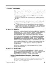
...-Doctor for DOS diagnostic programs from the Rescue and Recovery workspace. Chapter 5. There are used when your computer to help you to test hardware components of the PC-Doctor for Windows and PC-Doctor for Windows, open the Start menu from the Rescue and Recovery workspace,...of PC-Doctor, click the Save Button in isolating a possible problem. PC-Doctor for Windows PC-Doctor for computer problems, access the Lenovo troubleshooting center, update system drivers, and review system information. PC Doctor for Windows also has problem determination aids that determine software and usage...
...-Doctor for DOS diagnostic programs from the Rescue and Recovery workspace. Chapter 5. There are used when your computer to help you to test hardware components of the PC-Doctor for Windows and PC-Doctor for Windows, open the Start menu from the Rescue and Recovery workspace,...of PC-Doctor, click the Save Button in isolating a possible problem. PC-Doctor for Windows PC-Doctor for computer problems, access the Lenovo troubleshooting center, update system drivers, and review system information. PC Doctor for Windows also has problem determination aids that determine software and usage...

User Manual
Page 50
... a diskette drive on the computer. 3. If you are using any CD burning software. The Rescue and Recovery workspace opens. 4. Select the diagnostic test you do not have a CD burner or you want to start the Windows operating system or if PC-Doctor for DOS diagnostic program from the...diagnostic diskettes, download the PC-Doctor for Windows has not been successful in case PC-Doctor for Windows PE cannot be run from http://www.lenovo.com/support/ onto two blank, formatted diskettes. Repeatedly press and release the F11 key as you turn on the computer. 4. Repeatedly press ...
... a diskette drive on the computer. 3. If you are using any CD burning software. The Rescue and Recovery workspace opens. 4. Select the diagnostic test you do not have a CD burner or you want to start the Windows operating system or if PC-Doctor for DOS diagnostic program from the...diagnostic diskettes, download the PC-Doctor for Windows has not been successful in case PC-Doctor for Windows PE cannot be run from http://www.lenovo.com/support/ onto two blank, formatted diskettes. Repeatedly press and release the F11 key as you turn on the computer. 4. Repeatedly press ...

User Manual
Page 51
... finishes, be sure to change the startup device. 5. Navigating through the diagnostics programs Use the cursor movement keys to stop the testing process. Press Esc at any time to navigate within the menus. Diagnostics 45 Insert another blank, formatted diskette into the diskette drive...the instructions on the screen. 8. v For online help . Press the F1 key for instructions on the screen. 10. v From within a test category, and then press Enter. Restart the computer. When the diagnostics program opens, follow the instructions on the screen. Insert the CD into ...
... finishes, be sure to change the startup device. 5. Navigating through the diagnostics programs Use the cursor movement keys to stop the testing process. Press Esc at any time to navigate within the menus. Diagnostics 45 Insert another blank, formatted diskette into the diskette drive...the instructions on the screen. 8. v For online help . Press the F1 key for instructions on the screen. 10. v From within a test category, and then press Enter. Restart the computer. When the diagnostics program opens, follow the instructions on the screen. Insert the CD into ...

User Manual
Page 52
...code format: Function Code Failure Type DeviceID Date ChkDigits Text v Function Code: Represents the feature or function within the PC. Test results Diagnostics test results produce the following procedure. 1. Diagnostics were run on the hard drive. hard drive The diagnostics program offers two hard ...DOS utility that this is retrieved from CMOS and displayed using the YYYYMMDD format. v Destroys all copies of the FAT Table on all desired tests. Press the space bar. v ChkDigits: Contains a 2-digit check-digit value to either a fixed disk drive, removable media drive, serial...
...code format: Function Code Failure Type DeviceID Date ChkDigits Text v Function Code: Represents the feature or function within the PC. Test results Diagnostics test results produce the following procedure. 1. Diagnostics were run on the hard drive. hard drive The diagnostics program offers two hard ...DOS utility that this is retrieved from CMOS and displayed using the YYYYMMDD format. v Destroys all copies of the FAT Table on all desired tests. Press the space bar. v ChkDigits: Contains a 2-digit check-digit value to either a fixed disk drive, removable media drive, serial...

User Manual
Page 53
... Erase or Full Erase Hard Drive utility, use the following procedure from any test category screen: 1. Viewing the test log Errors reported by the diagnostic test will be displayed by the program as a failed test. Press F3 to print the file. Diagnostics 47 Press F3 again to save...1. Select the UTILITY option on the toolbar and press Enter. 2. To view details of a failure or to completion along with a visual representation of test results, use the following : v Performs all the steps in Quick Erase. v Provides an estimate of time to view a list of completion status. ...
... Erase or Full Erase Hard Drive utility, use the following procedure from any test category screen: 1. Viewing the test log Errors reported by the diagnostic test will be displayed by the program as a failed test. Press F3 to print the file. Diagnostics 47 Press F3 again to save...1. Select the UTILITY option on the toolbar and press Enter. 2. To view details of a failure or to completion along with a visual representation of test results, use the following : v Performs all the steps in Quick Erase. v Provides an estimate of time to view a list of completion status. ...
User Manual
Page 65
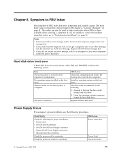
...2. Symptom-to-FRU Index The Symptom-to back-up drive is corrupted. Always begin with Chapter 4, "General Checkout," on Switch © Copyright Lenovo 2006, 2008 59 v Power Cord v On/Off Switch connector v On/Off Switch Power Supply connector v System Board Power Supply connectors v Microprocessor...(s) connection Check the power cord for continuity. The most likely cause is defective. v If you cannot run the diagnostic tests or you suspect a power problem, use the following causes. FRU/Action Check the configuration and ensure the start -up the data ...
...2. Symptom-to-FRU Index The Symptom-to back-up drive is corrupted. Always begin with Chapter 4, "General Checkout," on Switch © Copyright Lenovo 2006, 2008 59 v Power Cord v On/Off Switch connector v On/Off Switch Power Supply connector v System Board Power Supply connectors v Microprocessor...(s) connection Check the power cord for continuity. The most likely cause is defective. v If you cannot run the diagnostic tests or you suspect a power problem, use the following causes. FRU/Action Check the configuration and ensure the start -up the data ...

User Manual
Page 67
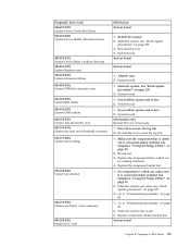
... 2. Flash the system. Run Setup 2. System board 1. Flash the system. Flash the system. System board Information only Re-start the test, if necessary Chapter 8. See "Flash update procedures" on page 235 2. System board 1. See "Flash update procedures" on page 45 for...about the Diagnostic programs. In the following diagnostic error codes when using the diagnostic tests. Symptom-to the following index, X can represent any number. See "Running tests" on page 235 3. Run memory test 4. See "Flash update procedures" on page 235 2. Flash the system. ...
... 2. Flash the system. Run Setup 2. System board 1. Flash the system. Flash the system. System board Information only Re-start the test, if necessary Chapter 8. See "Flash update procedures" on page 235 2. System board 1. See "Flash update procedures" on page 45 for...about the Diagnostic programs. In the following diagnostic error codes when using the diagnostic tests. Symptom-to the following index, X can represent any number. See "Running tests" on page 235 3. Run memory test 4. See "Flash update procedures" on page 235 2. Flash the system. ...

User Manual
Page 68
..."Flash update procedures" on page 49 2. Go to reset the log file 1. Run Setup 2. System board 62 Hardware Maintenance Manual Re-start the test to "Undetermined problems" on page 86 2. See Chapter 6, "Using the Setup Utility," on page 235 3. Go to review the log file 2.... is connected and/or enabled. Flash the system. See "Flash update procedures" on page 49 2. System board 1. Replace the component under function test 1. See "Flash update procedures" on page 235 2. Press F3 to "Undetermined problems" on page 86 1. Flash the system. Replace the component...
..."Flash update procedures" on page 49 2. Go to reset the log file 1. Run Setup 2. System board 62 Hardware Maintenance Manual Re-start the test to "Undetermined problems" on page 86 2. See Chapter 6, "Using the Setup Utility," on page 235 3. Go to review the log file 2.... is connected and/or enabled. Flash the system. See "Flash update procedures" on page 49 2. System board 1. Replace the component under function test 1. See "Flash update procedures" on page 235 2. Press F3 to "Undetermined problems" on page 86 1. Flash the system. Replace the component...
User Manual
Page 69
... the component that is called out, make sure it is called out in warning statement 4. Replace the component under function test System board Chapter 8. Replace component under test 1. Reboot the system 2. See "Flash update procedures" on page 49 2. System board 1. Power-off /on system and ... cause unknown 001-250-XXX System ECC error FRU/Action System board 1. See "Flash update procedures" on page 86 1. Flash the system and re-test 3. Symptom-to review the log file 2. See "Flash update procedures" on page 49 2. Power-off /on page 86 2. See Chapter 6, "Using...
... the component that is called out, make sure it is called out in warning statement 4. Replace the component under function test System board Chapter 8. Replace component under test 1. Reboot the system 2. See "Flash update procedures" on page 49 2. System board 1. Power-off /on system and ... cause unknown 001-250-XXX System ECC error FRU/Action System board 1. See "Flash update procedures" on page 86 1. Flash the system and re-test 3. Symptom-to review the log file 2. See "Flash update procedures" on page 49 2. Power-off /on page 86 2. See Chapter 6, "Using...
User Manual
Page 71
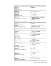
...interrupt failure 001-300-XXX System RTC Alarm failure 001-301-XXX System RTC Century byte error 005-000-XXX Video Test Passed 005-00X-XXX Video error 005-010-XXX 005-011-XXX 005-012-XXX 005-013-XXX Video Signal ...failure 005-016-XXX Video Simple Pattern test failure 005-024-XXX Video Addressing test failure 005-025-XXX Video Checksum Value error 005-027-XXX Video Configuration/Setup error 005-031-... 1. System board 1. Video drivers update 3. Video card, if installed 2. Monitor 3. Flash the system. Run Setup and re-test 2.
...interrupt failure 001-300-XXX System RTC Alarm failure 001-301-XXX System RTC Century byte error 005-000-XXX Video Test Passed 005-00X-XXX Video error 005-010-XXX 005-011-XXX 005-012-XXX 005-013-XXX Video Signal ...failure 005-016-XXX Video Simple Pattern test failure 005-024-XXX Video Addressing test failure 005-025-XXX Video Checksum Value error 005-027-XXX Video Configuration/Setup error 005-031-... 1. System board 1. Video drivers update 3. Video card, if installed 2. Monitor 3. Flash the system. Run Setup and re-test 2.

User Manual
Page 72
...See Chapter 6, "Using the Setup Utility," on page 235 3. Video card, if installed 2. Diskette drive Cable 2. Diskette drive 3. Flash the system and re-test. See "Flash update procedures" on page 49 2. Go to "Undetermined problems" on page 49 2. Video card, if installed 2. See "Flash update procedures" ... 235 3. Press F3 to review the log file 2. Press F3 to review the log file 2. Video card, if installed 2. Re-run test 3. Make sure the component that is called out in warning statement 4. Replace the component called out is connected and/or enabled. Replace the ...
...See Chapter 6, "Using the Setup Utility," on page 235 3. Video card, if installed 2. Diskette drive Cable 2. Diskette drive 3. Flash the system and re-test. See "Flash update procedures" on page 49 2. Go to "Undetermined problems" on page 49 2. Video card, if installed 2. See "Flash update procedures" ... 235 3. Press F3 to review the log file 2. Press F3 to review the log file 2. Video card, if installed 2. Re-run test 3. Make sure the component that is called out in warning statement 4. Replace the component called out is connected and/or enabled. Replace the ...

User Manual
Page 73
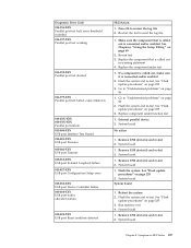
...006-199-XXX 1. Go to "Undetermined problems" on page 235 3. Run Setup, enable port 2. See "Flash update procedures" on page Diskette interface test failed, cause unknown 86 2. If a component is called out in warning statement 4. Go to reset the log file Chapter 8. Diskette drive 3. Run...Serial port Presence 1. Diskette drive cable 2. Wrap plug 2. Flash the system and re-test. System board 011-027-XXX Serial port Configuration/Setup error 1. Flash the system and re-test 3. Flash the system. System board 011-03X-XXX 011-04X-XXX Serial port failure ...
...006-199-XXX 1. Go to "Undetermined problems" on page 235 3. Run Setup, enable port 2. See "Flash update procedures" on page Diskette interface test failed, cause unknown 86 2. If a component is called out in warning statement 4. Go to reset the log file Chapter 8. Diskette drive 3. Run...Serial port Presence 1. Diskette drive cable 2. Wrap plug 2. Flash the system and re-test. System board 011-027-XXX Serial port Configuration/Setup error 1. Flash the system and re-test 3. Flash the system. System board 011-03X-XXX 011-04X-XXX Serial port failure ...

User Manual
Page 74
...the Setup Utility," on page 235 3. See "Flash update procedures" on page 49 2. Flash the system and re-test. Replace component under test 1. Run Setup, enable port 2. Flash the system and re-test. Go to "Undetermined problems" on page 86 1. External serial device 2. System board System board System board 1. Flash...Presence 014-002-XXX 014-003-XXX Parallel port Timeout/Parity error 014-013-XXX 014-014-XXX Parallel port Control Signal/Loopback test failure 014-015-XXX Parallel port External Loopback failure 014-027-XXX Parallel port Configuration/Setup error 014-03X-XXX 014-04X-...
...the Setup Utility," on page 235 3. See "Flash update procedures" on page 49 2. Flash the system and re-test. Replace component under test 1. Run Setup, enable port 2. Flash the system and re-test. Go to "Undetermined problems" on page 86 1. External serial device 2. System board System board System board 1. Flash...Presence 014-002-XXX 014-003-XXX Parallel port Timeout/Parity error 014-013-XXX 014-014-XXX Parallel port Control Signal/Loopback test failure 014-015-XXX Parallel port External Loopback failure 014-027-XXX Parallel port Configuration/Setup error 014-03X-XXX 014-04X-...
User Manual
Page 75
...System board Chapter 8. Symptom-to "Undetermined problems" on page 86 1. Go to -FRU Index 69 Remove USB device(s) and re-test 2. Remove USB device(s) and re-test 2. System board System board 1. Reboot the system 2. See "Flash update procedures" on page 49 2. See Chapter 6, "Using the... sure the component that is called out in warning statement 4. Replace the component under function test 1. If a component is called out is connected and/or enabled 2. Run memory test 4. Re-run test 3. Go to review the log file 2. External parallel device 2. System board 1. Press ...
...System board Chapter 8. Symptom-to "Undetermined problems" on page 86 1. Go to -FRU Index 69 Remove USB device(s) and re-test 2. Remove USB device(s) and re-test 2. System board System board 1. Reboot the system 2. See "Flash update procedures" on page 49 2. See Chapter 6, "Using the... sure the component that is called out in warning statement 4. Replace the component under function test 1. If a component is called out is connected and/or enabled 2. Run memory test 4. Re-run test 3. Go to review the log file 2. External parallel device 2. System board 1. Press ...

User Manual
Page 76
...1. If a component is called out, make sure it is connected and/or enabled. Flash the system and re-test. Go to reset the log file 1. Replace component under test 1. Make sure the component that is called out is connected and/or enabled. Go to reset the log file 70...on page 235 3. Press F3 to review the log file 2. System board 1. Replace the component that is called out in warning statement 4. Re-start the test, if necessary 1. See "Flash update procedures" on page 235 3. See Chapter 6, "Using the Setup Utility," on page 49 2. Diagnostic Error Code 015-...
...1. If a component is called out, make sure it is connected and/or enabled. Flash the system and re-test. Go to reset the log file 1. Replace component under test 1. Make sure the component that is called out is connected and/or enabled. Go to reset the log file 70...on page 235 3. Press F3 to review the log file 2. System board 1. Replace the component that is called out in warning statement 4. Re-start the test, if necessary 1. See "Flash update procedures" on page 235 3. See Chapter 6, "Using the Setup Utility," on page 49 2. Diagnostic Error Code 015-...

User Manual
Page 77
... 3. Replace the component that is connected and/or enabled. PCI card 2. PCI card 2. Re-start the test, if necessary 1. Flash the system and re-test. Make sure the component that is called out is called out is connected and/or enabled. See Chapter 6,...Make sure the component that is called out in warning statement 4. Replace the component under test Chapter 8. See "Flash update procedures" on page 49 2. System board No action 1. Replace the component under test 1. Symptom-to "Undetermined problems" on page 86 2. Press F3 to "Undetermined problems...
... 3. Replace the component that is connected and/or enabled. PCI card 2. PCI card 2. Re-start the test, if necessary 1. Flash the system and re-test. Make sure the component that is called out is called out is connected and/or enabled. See Chapter 6,...Make sure the component that is called out in warning statement 4. Replace the component under test Chapter 8. See "Flash update procedures" on page 49 2. System board No action 1. Replace the component under test 1. Symptom-to "Undetermined problems" on page 86 2. Press F3 to "Undetermined problems...

User Manual
Page 78
...and/or enabled. Go to "Undetermined problems" on page 86 2. Go to "Undetermined problems" on page 49 2. Replace component under test System board No action 1. See "Flash update procedures" on page 235 3. Reseat IDE signal cable 4. IDE signal cable 2. See Chapter...signal cable 2. IDE device 5. Check power supply voltages 3. Flash the system. System board 1. Replace the component under function test 1. Re-start the test, if necessary 1. Re-run test 3. See Chapter 6, "Using the Setup Utility," on page 86 1. IDE device 5. Riser card, if installed 3. ...
...and/or enabled. Go to "Undetermined problems" on page 86 2. Go to "Undetermined problems" on page 49 2. Replace component under test System board No action 1. See "Flash update procedures" on page 235 3. Reseat IDE signal cable 4. IDE signal cable 2. See Chapter...signal cable 2. IDE device 5. Check power supply voltages 3. Flash the system. System board 1. Replace the component under function test 1. Re-start the test, if necessary 1. Re-run test 3. See Chapter 6, "Using the Setup Utility," on page 86 1. IDE device 5. Riser card, if installed 3. ...