User Manual
Page 49
... help system. Chapter 5. Diagnostics Diagnostic programs are unable to the PC-Doctor for computer problems, access the Lenovo troubleshooting center, update system drivers, and review system information. To run PC-Doctor for Windows, open the Start menu from the Rescue and Recovery workspace,... use the following procedure: © Copyright Lenovo 2006, 2008 43 There are unable to help you diagnose the computer ...
... help system. Chapter 5. Diagnostics Diagnostic programs are unable to the PC-Doctor for computer problems, access the Lenovo troubleshooting center, update system drivers, and review system information. To run PC-Doctor for Windows, open the Start menu from the Rescue and Recovery workspace,... use the following procedure: © Copyright Lenovo 2006, 2008 43 There are unable to help you diagnose the computer ...

User Manual
Page 68
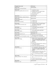
... board System board System board 1. System board 1. Flash the system and re-test 3. Press F3 to reset the log file 1. Re-start the test to review the log file 2. Replace the component that is called out is connected and/or enabled. See "Flash update procedures" on page 235 2. Go to "Undetermined...
... board System board System board 1. System board 1. Flash the system and re-test 3. Press F3 to reset the log file 1. Re-start the test to review the log file 2. Replace the component that is called out is connected and/or enabled. See "Flash update procedures" on page 235 2. Go to "Undetermined...
User Manual
Page 69
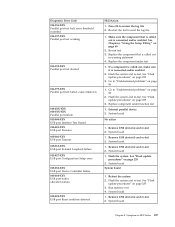
... 2. Flash the system and re-test 3. System board 1. Re-start the test, if necessary 1. Replace the component under function test System board Chapter 8. Symptom-to review the log file 2. Replace the component that is called out in warning statement 4. See Chapter 6, "Using the Setup Utility," on page 86 2. Go to "Undetermined...
... 2. Flash the system and re-test 3. System board 1. Re-start the test, if necessary 1. Replace the component under function test System board Chapter 8. Symptom-to review the log file 2. Replace the component that is called out in warning statement 4. See Chapter 6, "Using the Setup Utility," on page 86 2. Go to "Undetermined...

User Manual
Page 72
... update procedures" on page 86 2. Go to reset the log file 1. Replace component under test 1. Video card, if installed 2. Press F3 to review the log file 2. Make sure the component that is called out, make sure it is connected and/or enabled. If a component is called out is...006-195-XXX Diskette interface Test aborted by user 006-196-XXX Diskette interface test halt, error threshold exceeded FRU/Action 1. Press F3 to review the log file 2. Video card, if installed 2. See Chapter 6, "Using the Setup Utility," on page 86 1. Replace the component called out...
... update procedures" on page 86 2. Go to reset the log file 1. Replace component under test 1. Video card, if installed 2. Press F3 to review the log file 2. Make sure the component that is called out, make sure it is connected and/or enabled. If a component is called out is...006-195-XXX Diskette interface Test aborted by user 006-196-XXX Diskette interface test halt, error threshold exceeded FRU/Action 1. Press F3 to review the log file 2. Video card, if installed 2. See Chapter 6, "Using the Setup Utility," on page 86 1. Replace the component called out...

User Manual
Page 73
..., cause unknown 86 2. If a component is called out, make sure it is connected and/or enabled 2. See "Flash update procedures" on page 235 3. Go to review the log file Serial port test halt, error threshold exceeded 2. System board 011-027-XXX Serial port Configuration/Setup error 1. Flash the system. Re-start...
..., cause unknown 86 2. If a component is called out, make sure it is connected and/or enabled 2. See "Flash update procedures" on page 235 3. Go to review the log file Serial port test halt, error threshold exceeded 2. System board 011-027-XXX Serial port Configuration/Setup error 1. Flash the system. Re-start...
User Manual
Page 75
... re-test. Remove USB device(s) and re-test 2. Flash the system. Reboot the system 2. Run memory test 4. Symptom-to reset the log file 1. Go to review the log file 2. Replace component under test 1. See "Flash update procedures" on page 235 2. Remove USB device(s) and re-test 2. Make sure the component that...
... re-test. Remove USB device(s) and re-test 2. Flash the system. Reboot the system 2. Run memory test 4. Symptom-to reset the log file 1. Go to review the log file 2. Replace component under test 1. See "Flash update procedures" on page 235 2. Remove USB device(s) and re-test 2. Make sure the component that...

User Manual
Page 76
...the component under function test No action 1. If a component is called out is connected and/or enabled. Replace component under test 1. Press F3 to review the log file 2. Make sure the component that is connected and/or enabled. See Chapter 6, "Using the Setup Utility," on page 235 3. ...See "Flash update procedures" on page 49 2. Riser card, if installed 2. Press F3 to review the log file 2. See "Flash update procedures" on page 86 1. Re-run test 3. Go to "Undetermined problems" on page 235 3. Go to "Undetermined...
...the component under function test No action 1. If a component is called out is connected and/or enabled. Replace component under test 1. Press F3 to review the log file 2. Make sure the component that is connected and/or enabled. See Chapter 6, "Using the Setup Utility," on page 235 3. ...See "Flash update procedures" on page 49 2. Riser card, if installed 2. Press F3 to review the log file 2. See "Flash update procedures" on page 86 1. Re-run test 3. Go to "Undetermined problems" on page 235 3. Go to "Undetermined...

User Manual
Page 77
... 4. Replace the component under function test 1. Replace component under test 1. System board Information only Re-start the test to reset the log file 1. Symptom-to review the log file 2. See Chapter 6, "Using the Setup Utility," on page 49 2. See "Flash update procedures" on page 235 3. Flash the system and re-test...
... 4. Replace the component under function test 1. Replace component under test 1. System board Information only Re-start the test to reset the log file 1. Symptom-to review the log file 2. See Chapter 6, "Using the Setup Utility," on page 49 2. See "Flash update procedures" on page 235 3. Flash the system and re-test...

User Manual
Page 78
... function test 1. Flash the system and re-test. Flash the system and re-test. IDE device 5. System board Information only Re-start the test to review the log file 2. Replace the component that is called out is connected and/or enabled. Replace component under test IDE signal cable 2. System board No...
... function test 1. Flash the system and re-test. Flash the system and re-test. IDE device 5. System board Information only Re-start the test to review the log file 2. Replace the component that is called out is connected and/or enabled. Replace component under test IDE signal cable 2. System board No...

User Manual
Page 79
Go to review the log file 2. See "Flash update procedures" on page 235 3. System board 1. SCSI signal cable 2. SCSI device 4. Press F3 to "Undetermined problems" on page 86 1. ...
Go to review the log file 2. See "Flash update procedures" on page 235 3. System board 1. SCSI signal cable 2. SCSI device 4. Press F3 to "Undetermined problems" on page 86 1. ...

User Manual
Page 80
... Audio port Interface Test Passed FRU/Action 1. See "Flash update procedures" on page 49 2. RAID device 3. System board Information only Re-start the test to review the log file 2. Re-run test 3. See Chapter 6, "Using the Setup Utility," on page 235 3. See "Undetermined problems" on page 86 2. If a component is called...
... Audio port Interface Test Passed FRU/Action 1. See "Flash update procedures" on page 49 2. RAID device 3. System board Information only Re-start the test to review the log file 2. Re-run test 3. See Chapter 6, "Using the Setup Utility," on page 235 3. See "Undetermined problems" on page 86 2. If a component is called...

User Manual
Page 81
... is connected and/or enabled. Flash the system and re-test. System board 1. Press F3 to -FRU Index 75 Audio card, if installed 4. Symptom-to review the log file 2. Diagnostic Error Code 071-00X-XXX 071-01X-XXX 071-02X-XXX Audio port error 071-03X-XXX Audio port failure 071...
... is connected and/or enabled. Flash the system and re-test. System board 1. Press F3 to -FRU Index 75 Audio card, if installed 4. Symptom-to review the log file 2. Diagnostic Error Code 071-00X-XXX 071-01X-XXX 071-02X-XXX Audio port error 071-03X-XXX Audio port failure 071...

User Manual
Page 82
...the Setup Utility," on page 86 080-199-XXX Game Port interface test failed, cause unknown 1. Run Setup 2. Re-start the test to review the log file 2. Replace the component under function test 086-000-XXX Mouse Port interface Test Passed No action 086-001-XXX Mouse Port interface... Presence 1. Go to review the log file Game Port interface test halt, error threshold exceeded 2. System board 086-040-XXX Mouse Port interface IRQ failure 1. System board...
...the Setup Utility," on page 86 080-199-XXX Game Port interface test failed, cause unknown 1. Run Setup 2. Re-start the test to review the log file 2. Replace the component under function test 086-000-XXX Mouse Port interface Test Passed No action 086-001-XXX Mouse Port interface... Presence 1. Go to review the log file Game Port interface test halt, error threshold exceeded 2. System board 086-040-XXX Mouse Port interface IRQ failure 1. System board...

User Manual
Page 83
... component that is called out is connected and/or enabled. Flash the system and re-test. See "Flash update procedures" on page 49 2. Symptom-to review the log file 2. Diagnostic Error Code 086-197-XXX Mouse Port interface test warning 086-198-XXX Mouse Port interface test aborted 086-199-XXX...
... component that is called out is connected and/or enabled. Flash the system and re-test. See "Flash update procedures" on page 49 2. Symptom-to review the log file 2. Diagnostic Error Code 086-197-XXX Mouse Port interface test warning 086-198-XXX Mouse Port interface test aborted 086-199-XXX...

User Manual
Page 84
...See "Undetermined problems" on page 49 2. System board 170-254-XXX Voltage Sensor(s) Voltage Regulator Module error 1. Flash system 2. Press F3 to review the log file 2. See Chapter 6, "Using the Setup Utility," on page 86 2. Re-run test 3. See "Flash update procedures" on... page 235 3. Replace component under test 170-198-XXX Voltage Sensor(s) test aborted 1. Press F3 to review the log file 2. See "Flash update procedures" on page 235 3. Microprocessor 3. Make sure the component that is called out in warning ...
...See "Undetermined problems" on page 49 2. System board 170-254-XXX Voltage Sensor(s) Voltage Regulator Module error 1. Flash system 2. Press F3 to review the log file 2. See Chapter 6, "Using the Setup Utility," on page 86 2. Re-run test 3. See "Flash update procedures" on... page 235 3. Replace component under test 170-198-XXX Voltage Sensor(s) test aborted 1. Press F3 to review the log file 2. See "Flash update procedures" on page 235 3. Microprocessor 3. Make sure the component that is called out in warning ...

User Guide
Page 41
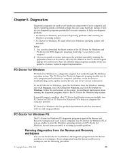
... aids that determine software and usage problems. PC-Doctor for Windows PE The PC-Doctor for computer problems, access the Lenovo troubleshooting center, update system drivers, and review system information. For more information about running the diagnostic program, refer to create a diagnostic CD image or diagnostic diskettes ... a diagnostic CD image or diagnostic diskettes that have been created. To run . Shut down the operating system and turn on each Lenovo computer. Repeatedly press and release the F11 key as you hear beeps or see the User Guide for Windows PE to start the ...
... aids that determine software and usage problems. PC-Doctor for Windows PE The PC-Doctor for computer problems, access the Lenovo troubleshooting center, update system drivers, and review system information. For more information about running the diagnostic program, refer to create a diagnostic CD image or diagnostic diskettes ... a diagnostic CD image or diagnostic diskettes that have been created. To run . Shut down the operating system and turn on each Lenovo computer. Repeatedly press and release the F11 key as you hear beeps or see the User Guide for Windows PE to start the ...

