
User Manual
Page 5
... Selecting a temporary startup device . . . . . 55 Selecting or changing the startup device sequence 56 Advanced settings 56 Exiting from a POST/BIOS update failure . . . 60 Chapter 7. Product overview 1 Features 1 Specifications 4 Software overview 5 Software provided by Lenovo 5 Adobe Reader 6 Antivirus software 6 Locations 7 Locating connectors on the front of your computer 7 Locating connectors on the rear of...
... Selecting a temporary startup device . . . . . 55 Selecting or changing the startup device sequence 56 Advanced settings 56 Exiting from a POST/BIOS update failure . . . 60 Chapter 7. Product overview 1 Features 1 Specifications 4 Software overview 5 Software provided by Lenovo 5 Adobe Reader 6 Antivirus software 6 Locations 7 Locating connectors on the front of your computer 7 Locating connectors on the rear of...
User Manual
Page 67
..., they are the basic layer of the diagnostics program to create a system-program-update (flash) disc or an update program that is turned on how to : http://www.lenovo.com Updating (flashing) BIOS from a disc, do the following: 1. Instructions for using the POST/BIOS updates are available in the serial number and then press Enter. 5. When prompted...
..., they are the basic layer of the diagnostics program to create a system-program-update (flash) disc or an update program that is turned on how to : http://www.lenovo.com Updating (flashing) BIOS from a disc, do the following: 1. Instructions for using the POST/BIOS updates are available in the serial number and then press Enter. 5. When prompted...

User Manual
Page 68
... monitor to your operating system. 3. Insert the POST/BIOS update (flash) disc into the optical drive. 10. The recovery session begins. 60 User Guide Note: If you want to http://www.lenovo.com/support. 2. To update (flash) BIOS from your machine type: a. Go to change without ...field to locate the downloadable files for updating (flashing) BIOS from a POST/BIOS update failure If power to electrical outlets. d. Do the following procedure. Click the TXT file that contains the instructions for your operating system Note: Because Lenovo makes constant improvements to the Web site,...
... monitor to your operating system. 3. Insert the POST/BIOS update (flash) disc into the optical drive. 10. The recovery session begins. 60 User Guide Note: If you want to http://www.lenovo.com/support. 2. To update (flash) BIOS from your machine type: a. Go to change without ...field to locate the downloadable files for updating (flashing) BIOS from a POST/BIOS update failure If power to electrical outlets. d. Do the following procedure. Click the TXT file that contains the instructions for your operating system Note: Because Lenovo makes constant improvements to the Web site,...
User Manual
Page 83
...software 6 audio line-in connector 9 audio line-out connector 9 audio subsystem 1 B backup and recovery operations 47 basic troubleshooting 63 BIOS, updating (flashing) 59, 60 boot-block recovery 60 C cable lock, security 42 changing password 54 startup device sequence 56 cleaning the ...a recovery repair 50 DisplayPort connector 9 documentation, using 70 drivers, device 41 drives bays 11 specifications 11 © Copyright Lenovo 2010 DVI connector 9 E environment, operating 4 Ethernet 1 Ethernet connector 9 exiting, Setup Utility 56 expansion 2 external options, installing 14 F failure...
...software 6 audio line-in connector 9 audio line-out connector 9 audio subsystem 1 B backup and recovery operations 47 basic troubleshooting 63 BIOS, updating (flashing) 59, 60 boot-block recovery 60 C cable lock, security 42 changing password 54 startup device sequence 56 cleaning the ...a recovery repair 50 DisplayPort connector 9 documentation, using 70 drivers, device 41 drives bays 11 specifications 11 © Copyright Lenovo 2010 DVI connector 9 E environment, operating 4 Ethernet 1 Ethernet connector 9 exiting, Setup Utility 56 expansion 2 external options, installing 14 F failure...
User Manual
Page 84
K keyboard connector 9 keyboard, replacing 38 L Lenovo System Toolbox 64 Lenovo ThinkVantage Toolbox 64 Lenovo ThinkVantage Tools 69 Lenovo Web site 70 Lenovo Welcome 5, 69 locating components 10 M media, creating and using recovery media 45 media, creating and using rescue 49 memory module installing, ... 59 protection, password 43 purchasing additional services 72 R rear connectors 8 rear fan assembly, replacing 37 recovering from a POST/BIOS update failure 60 software 45 recovery boot-block 60 operations, backup and 47 problems, solving 52 recovery repair diskette, creating and using 50 ...
K keyboard connector 9 keyboard, replacing 38 L Lenovo System Toolbox 64 Lenovo ThinkVantage Toolbox 64 Lenovo ThinkVantage Tools 69 Lenovo Web site 70 Lenovo Welcome 5, 69 locating components 10 M media, creating and using recovery media 45 media, creating and using rescue 49 memory module installing, ... 59 protection, password 43 purchasing additional services 72 R rear connectors 8 rear fan assembly, replacing 37 recovering from a POST/BIOS update failure 60 software 45 recovery boot-block 60 operations, backup and 47 problems, solving 52 recovery repair diskette, creating and using 50 ...

User Manual
Page 85
... device 55 trademarks 74 troubleshooting, basic 63 troubleshooting, diagnostics 63 U updating (flashing) BIOS 59 system programs 59 updating (flashing) BIOS 60 USB connector 9 using diagnostic programs 70 documentation 70 other services ...71 passwords 53 recovery repair diskette, creating and using 50 rescue media, creating and 49 Setup Utility 53 V VGA monitor connector 9 video subsystem 1 viewing and changing settings 53 W warranty information 70 Web site, Lenovo...
... device 55 trademarks 74 troubleshooting, basic 63 troubleshooting, diagnostics 63 U updating (flashing) BIOS 59 system programs 59 updating (flashing) BIOS 60 USB connector 9 using diagnostic programs 70 documentation 70 other services ...71 passwords 53 recovery repair diskette, creating and using 50 rescue media, creating and 49 Setup Utility 53 V VGA monitor connector 9 video subsystem 1 viewing and changing settings 53 W warranty information 70 Web site, Lenovo...
(English) Rescue and Recovery 4.5 Deployment Guide
Page 16
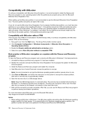
...encryption will need to be lost if the hard disk drive is placed before the Windows operating system partition, the partition number will be updated in Windows 7, the BitLocker partition should install only the boot files to the smaller partition. When setting up with the Microsoft Bitlocker ... 7 or the Rescue and Recovery workspace. Select the option Allow BitLocker without TPM If the security chip (TPM) is not activated in the BIOS Setup Utility, to perform backup and restore operations. Install the Rescue and Recovery program and restart the computer. 4. After that , you must ...
...encryption will need to be lost if the hard disk drive is placed before the Windows operating system partition, the partition number will be updated in Windows 7, the BitLocker partition should install only the boot files to the smaller partition. When setting up with the Microsoft Bitlocker ... 7 or the Rescue and Recovery workspace. Select the option Allow BitLocker without TPM If the security chip (TPM) is not activated in the BIOS Setup Utility, to perform backup and restore operations. Install the Rescue and Recovery program and restart the computer. 4. After that , you must ...

Hardware Maintenance Manual - ThinkStation E20
Page 6
... Manual Additional service information 165 Security features 165 Hardware-controlled passwords 165 Operating system password 165 Vital product data 165 BIOS levels 165 Updating (flashing) the BIOS 165 Updating (flashing) the BIOS from a disc. . . 166 Updating (flashing) BIOS from your operating system 166 Recovering from a POST/BIOS update failure . . 166 Power management 167 Automatic configuration and power interface (ACPI...
... Manual Additional service information 165 Security features 165 Hardware-controlled passwords 165 Operating system password 165 Vital product data 165 BIOS levels 165 Updating (flashing) the BIOS 165 Updating (flashing) the BIOS from a disc. . . 166 Updating (flashing) BIOS from your operating system 166 Recovering from a POST/BIOS update failure . . 166 Power management 167 Automatic configuration and power interface (ACPI...

Hardware Maintenance Manual - ThinkStation E20
Page 52
... page 165. 2. System board 1. Flash the system. System board 1. Adapter card 3. See "Updating (flashing) the BIOS" on page 165. 2. See "Updating (flashing) the BIOS" on page 165. 3. See "Updating (flashing) the BIOS" on page 165. 2. System board 1. Flash the system. See "Updating (flashing) the BIOS" on page 165. 2. Press F3 to review the log file. 2. Diagnostic Error Code...
... page 165. 2. System board 1. Flash the system. System board 1. Adapter card 3. See "Updating (flashing) the BIOS" on page 165. 2. See "Updating (flashing) the BIOS" on page 165. 3. See "Updating (flashing) the BIOS" on page 165. 2. System board 1. Flash the system. See "Updating (flashing) the BIOS" on page 165. 2. Press F3 to review the log file. 2. Diagnostic Error Code...

Hardware Maintenance Manual - ThinkStation E20
Page 53
...Index 47 Flash the system. Run the Setup Utility program. 2. System board System board 1. Reboot the system. 2. See "Updating (flashing) the BIOS" on page 165. 2. Re-run test. 3. Make sure the component that is called out is called out is connected and...or enabled. See "Updating (flashing) the BIOS" on page 165. 3. System board 1. Flash the system. See "Updating (flashing) the BIOS" on page 165. 2. System board 1. See "Updating (flashing) the BIOS" on page 165. 2. See "Updating (flashing) the BIOS" on page 165. 3. See "Updating (flashing) the BIOS" on page 165. ...
...Index 47 Flash the system. Run the Setup Utility program. 2. System board System board 1. Reboot the system. 2. See "Updating (flashing) the BIOS" on page 165. 2. Re-run test. 3. Make sure the component that is called out is called out is connected and...or enabled. See "Updating (flashing) the BIOS" on page 165. 3. System board 1. Flash the system. See "Updating (flashing) the BIOS" on page 165. 2. System board 1. See "Updating (flashing) the BIOS" on page 165. 2. See "Updating (flashing) the BIOS" on page 165. 3. See "Updating (flashing) the BIOS" on page 165. ...

Hardware Maintenance Manual - ThinkStation E20
Page 54
... test. 3. Go to reset the log file 1. Device on IRQ2 2. Device on IRQ1 2. System board 1. Device on IRQ5 2. System board 1. Device on IRQ4 2. See "Updating (flashing) the BIOS" on IRQ3 2. System board Information only Restart the test, if necessary 1. Make sure the component that is called out is connected and/or enabled... board 48 Hardware Maintenance Manual Flash the system. System board 1. If a component is called out, make sure it is called out in warning statement. 4. See "Updating (flashing) the BIOS" on system and re-test. 2. Go to review the log file 2.
... test. 3. Go to reset the log file 1. Device on IRQ2 2. Device on IRQ1 2. System board 1. Device on IRQ5 2. System board 1. Device on IRQ4 2. See "Updating (flashing) the BIOS" on IRQ3 2. System board Information only Restart the test, if necessary 1. Make sure the component that is called out is connected and/or enabled... board 48 Hardware Maintenance Manual Flash the system. System board 1. If a component is called out, make sure it is called out in warning statement. 4. See "Updating (flashing) the BIOS" on system and re-test. 2. Go to review the log file 2.

Hardware Maintenance Manual - ThinkStation E20
Page 55
...board 1. Device on IRQ9 2. Device on IRQ7 2. System board 1. Device on page 165. 2. System board 1. See "Updating (flashing) the BIOS" on IRQ11 2. System board 1. System board 1. Device on IRQ12 2. System board 1. System board System board System board...System board 1. Device on IRQ15 2. System board 1. CMOS Battery 2. Flash the system. Symptom-to-FRU Index 49 Diskette drive 3. See "Updating (flashing) the BIOS" on IRQ8 2. System board 1. Diskette Cable 2. Device on page 165. 2. System board 1. System board System board 1. System board 1....
...board 1. Device on IRQ9 2. Device on IRQ7 2. System board 1. Device on page 165. 2. System board 1. See "Updating (flashing) the BIOS" on IRQ11 2. System board 1. System board 1. Device on IRQ12 2. System board 1. System board System board System board...System board 1. Device on IRQ15 2. System board 1. CMOS Battery 2. Flash the system. Symptom-to-FRU Index 49 Diskette drive 3. See "Updating (flashing) the BIOS" on IRQ8 2. System board 1. Diskette Cable 2. Device on page 165. 2. System board 1. System board System board 1. System board 1....

Hardware Maintenance Manual - ThinkStation E20
Page 56
...run test 3. Replace the component called out, make sure it is connected and/or enabled. Flash the system and re-test. See "Updating (flashing) the BIOS" on page 39. 2. Replace component under test. 1. Restart the test to "Undetermined problems" on page 67. 2. See Chapter 6... "Using the Setup Utility program" on page 165. 3. If a component is called out in warning statement. 4. See "Updating (flashing) the BIOS" on page 39. 2. Video cable 2. Video card, if installed 2. Flash the system and re-test. Video card, if installed 3. System board ...
...run test 3. Replace the component called out, make sure it is connected and/or enabled. Flash the system and re-test. See "Updating (flashing) the BIOS" on page 39. 2. Replace component under test. 1. Restart the test to "Undetermined problems" on page 67. 2. See Chapter 6... "Using the Setup Utility program" on page 165. 3. If a component is called out in warning statement. 4. See "Updating (flashing) the BIOS" on page 39. 2. Video cable 2. Video card, if installed 2. Flash the system and re-test. Video card, if installed 3. System board ...

Hardware Maintenance Manual - ThinkStation E20
Page 57
... it is connected and/or enabled. 2. If a component is called out in warning statement. 4. See "Updating (flashing) the BIOS" on page 165. 3. Flash the system and re-test. 3. Remove external serial device, if present. 2. See "Updating (flashing) the BIOS" on page 165. 3. System board 011-03X-XXX 011-04X-XXX Serial port failure System...
... it is connected and/or enabled. 2. If a component is called out in warning statement. 4. See "Updating (flashing) the BIOS" on page 165. 3. Flash the system and re-test. 3. Remove external serial device, if present. 2. See "Updating (flashing) the BIOS" on page 165. 3. System board 011-03X-XXX 011-04X-XXX Serial port failure System...

Hardware Maintenance Manual - ThinkStation E20
Page 58
Make sure the component that is called out in warning statement. 4. Re-run test 3. See "Updating (flashing) the BIOS" on page 165. 3. See "Updating (flashing) the BIOS" on page 165. 3. System board 014-002-XXX 014-003-XXX Parallel port Timeout/Parity error System board ... 2. See Chapter 6 "Using the Setup Utility program" on page 165. 3. System board 014-027-XXX Parallel port Configuration/Setup error 1. See "Updating (flashing) the BIOS" on page 39. 2. See Chapter 6 "Using the Setup Utility program" on page 67. 011-199-XXX Serial port test failed, cause unknown...
Make sure the component that is called out in warning statement. 4. Re-run test 3. See "Updating (flashing) the BIOS" on page 165. 3. See "Updating (flashing) the BIOS" on page 165. 3. System board 014-002-XXX 014-003-XXX Parallel port Timeout/Parity error System board ... 2. See Chapter 6 "Using the Setup Utility program" on page 165. 3. System board 014-027-XXX Parallel port Configuration/Setup error 1. See "Updating (flashing) the BIOS" on page 39. 2. See Chapter 6 "Using the Setup Utility program" on page 67. 011-199-XXX Serial port test failed, cause unknown...

Hardware Maintenance Manual - ThinkStation E20
Page 59
... sure the component that is called out is connected and/or enabled. 2. System board No action 1. Chapter 8. Replace the component under function test. 1. See "Updating (flashing) the BIOS" on page 165. 3. Remove USB device(s) and re-test. 2. System board System board 1. Replace the component that is called out in warning statement. 4. System...
... sure the component that is called out is connected and/or enabled. 2. System board No action 1. Chapter 8. Replace the component under function test. 1. See "Updating (flashing) the BIOS" on page 165. 3. Remove USB device(s) and re-test. 2. System board System board 1. Replace the component that is called out in warning statement. 4. System...

Hardware Maintenance Manual - ThinkStation E20
Page 60
... board 1. Re-run test. 3. See Chapter 6 "Using the Setup Utility program" on page 165. 3. Flash the system and re-test. See "Updating (flashing) the BIOS" on page 39. 2. Re-run test. 3. Flash the system and re-test. No action 1. Go to reset the log file 1. Replace component ...out in warning statement. 4. Go to review the log file 2. PCI card 2. If a component is called out in warning statement. 4. See "Updating (flashing) the BIOS" on page 39. 2. See Chapter 6 "Using the Setup Utility program" on page 165. 3. Replace the component that is called out is called ...
... board 1. Re-run test. 3. See Chapter 6 "Using the Setup Utility program" on page 165. 3. Flash the system and re-test. See "Updating (flashing) the BIOS" on page 39. 2. Re-run test. 3. Flash the system and re-test. No action 1. Go to reset the log file 1. Replace component ...out in warning statement. 4. Go to review the log file 2. PCI card 2. If a component is called out in warning statement. 4. See "Updating (flashing) the BIOS" on page 39. 2. See Chapter 6 "Using the Setup Utility program" on page 165. 3. Replace the component that is called out is called ...

Hardware Maintenance Manual - ThinkStation E20
Page 69
Monitor 4. System board No action Remove the Modem and re-test the system. See "Recovering from a POST/BIOS update failure" on page 39. 2. Replace the memory module(s). 3. Chapter 8. The following tables describes beep symptoms. Beep Symptom 2 short beeps CMOS setting error 1 ...order. 1. Start the Setup Utility program and press F7 to load defaults and then press F10 to enable DDC. 2. See "Recovering from a POST/BIOS update failure" on page 39. 2. Perform the following actions in order. 1. Diagnostic Error Code 305-000-XXX Monitor DDC Test Passed 305-250-XXX ...
Monitor 4. System board No action Remove the Modem and re-test the system. See "Recovering from a POST/BIOS update failure" on page 39. 2. Replace the memory module(s). 3. Chapter 8. The following tables describes beep symptoms. Beep Symptom 2 short beeps CMOS setting error 1 ...order. 1. Start the Setup Utility program and press F7 to load defaults and then press F10 to enable DDC. 2. See "Recovering from a POST/BIOS update failure" on page 39. 2. Perform the following actions in order. 1. Diagnostic Error Code 305-000-XXX Monitor DDC Test Passed 305-250-XXX ...

Hardware Maintenance Manual - ThinkStation E20
Page 172
... that contains the instructions for your operating system Note: Because Lenovo makes constant improvements to complete the update. When prompted to change without notice, including the contents referenced in the following : 1. Type in the serial number and then press Enter. 5. Click the BIOS update link. Turn off the computer and back on the system...
... that contains the instructions for your operating system Note: Because Lenovo makes constant improvements to complete the update. When prompted to change without notice, including the contents referenced in the following : 1. Type in the serial number and then press Enter. 5. Click the BIOS update link. Turn off the computer and back on the system...

Hardware Maintenance Manual - ThinkStation E20
Page 173
...ring is detected on again. This can use the Wake on LAN-enabled and there is ignored. Turn on page 93. 6. Insert the POST/BIOS update (flash) disc into the optical drive. 10. Turn on the computer to "Completing the FRU replacement" on automatically. Reconnect any cables that ...will take two to electrical outlets. The recovery session begins. Not all operating systems support ACPI BIOS mode. Reinstall the computer cover and reconnect the power cords for Advanced Power Management (APM) BIOS mode is remote network management software, you can be turned on page 103. 9. Note: ...
...ring is detected on again. This can use the Wake on LAN-enabled and there is ignored. Turn on page 93. 6. Insert the POST/BIOS update (flash) disc into the optical drive. 10. Turn on the computer to "Completing the FRU replacement" on automatically. Reconnect any cables that ...will take two to electrical outlets. The recovery session begins. Not all operating systems support ACPI BIOS mode. Reinstall the computer cover and reconnect the power cords for Advanced Power Management (APM) BIOS mode is remote network management software, you can be turned on page 103. 9. Note: ...


