
Hardware Maintenance Manual (HMM) - ThinkStation D30
Page 5
... 30 Additional information resources 31 Chapter 4. Diagnostics 35 Lenovo Solution Center 35 Chapter 6. General Checkout . . . . . 33 Problem determination tips 33 Chapter 5. Symptom-to-FRU Index . . 49 Hard disk drive boot error 49 Power Supply Problems 49 Beep symptoms 49 POST error codes 50... the startup device sequence 40 Enabling ErP compliance mode and Deep Sx . . 40 Exiting the Setup Utility program 41 © Copyright Lenovo 2012 Chapter 7. Locations 55 Locating connectors, controls, and indicators on the front of your computer 55 Locating connectors on the rear of ...
... 30 Additional information resources 31 Chapter 4. Diagnostics 35 Lenovo Solution Center 35 Chapter 6. General Checkout . . . . . 33 Problem determination tips 33 Chapter 5. Symptom-to-FRU Index . . 49 Hard disk drive boot error 49 Power Supply Problems 49 Beep symptoms 49 POST error codes 50... the startup device sequence 40 Enabling ErP compliance mode and Deep Sx . . 40 Exiting the Setup Utility program 41 © Copyright Lenovo 2012 Chapter 7. Locations 55 Locating connectors, controls, and indicators on the front of your computer 55 Locating connectors on the rear of ...

Hardware Maintenance Manual (HMM) - ThinkStation D30
Page 6
... Index 111 iv ThinkStation Hardware Maintenance Manual Installing or replacing a hard disk drive . . . 83 Installing or replacing a hard disk drive enablement module 87 Replacing the front audio and USB assembly 88 Replacing the internal speaker 89 Installing or replacing the microprocessor . . 90 Replacing the system board 99 Replacing the power supply assembly . . . 102...
... Index 111 iv ThinkStation Hardware Maintenance Manual Installing or replacing a hard disk drive . . . 83 Installing or replacing a hard disk drive enablement module 87 Replacing the front audio and USB assembly 88 Replacing the internal speaker 89 Installing or replacing the microprocessor . . 90 Replacing the system board 99 Replacing the power supply assembly . . . 102...

Hardware Maintenance Manual (HMM) - ThinkStation D30
Page 10
... medical aid. 4 ThinkStation Hardware Maintenance Manual Switch off the power, if necessary. - Use only one hand when working with live electrical circuits with the power on electrical equipment; these hazards are moist floors, nongrounded power extension cables, power surges, and missing safety... approved probe leads and accessories for that has hazardous voltages. • Disconnect all power before: - Power supply units - Pumps - Use caution; Send another person, familiar with powered-on when they are in your pocket or behind your electrical hand tools for possible...
... medical aid. 4 ThinkStation Hardware Maintenance Manual Switch off the power, if necessary. - Use only one hand when working with live electrical circuits with the power on electrical equipment; these hazards are moist floors, nongrounded power extension cables, power surges, and missing safety... approved probe leads and accessories for that has hazardous voltages. • Disconnect all power before: - Power supply units - Pumps - Use caution; Send another person, familiar with powered-on when they are in your pocket or behind your electrical hand tools for possible...
Hardware Maintenance Manual (HMM) - ThinkStation D30
Page 12
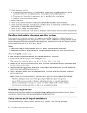
... against ESD damage. - A third-wire ground connector in the following languages: 6 ThinkStation Hardware Maintenance Manual Attach the ESD ground clip to protect against your clothing. The power cord should be the appropriate type as specified in protective packages until they exceed the ...on ac-operated computers. Proper grounding of any frame ground, ground braid, or green-wire ground. - 3. Make sure that the power-supply cover fasteners (screws or rivets) have been certified (ISO 9000) as to eliminate static on these systems. - b. Use good judgment...
... against ESD damage. - A third-wire ground connector in the following languages: 6 ThinkStation Hardware Maintenance Manual Attach the ESD ground clip to protect against your clothing. The power cord should be the appropriate type as specified in protective packages until they exceed the ...on ac-operated computers. Proper grounding of any frame ground, ground braid, or green-wire ground. - 3. Make sure that the power-supply cover fasteners (screws or rivets) have been certified (ISO 9000) as to eliminate static on these systems. - b. Use good judgment...

Hardware Maintenance Manual (HMM) - ThinkStation D30
Page 14
...power switch on the power supply do not view directly with the same module type made by local ordinances or regulations. Removing the covers of . Do not: • Throw or immerse into the beam, do not turn off the electrical current supplied to hazardous laser radiation. To remove all electrical current from the power source. 8 ThinkStation... Hardware Maintenance Manual There are disconnected from the device, ensure that all power cords are no...
...power switch on the power supply do not view directly with the same module type made by local ordinances or regulations. Removing the covers of . Do not: • Throw or immerse into the beam, do not turn off the electrical current supplied to hazardous laser radiation. To remove all electrical current from the power source. 8 ThinkStation... Hardware Maintenance Manual There are disconnected from the device, ensure that all power cords are no...

Hardware Maintenance Manual (HMM) - ThinkStation D30
Page 47
Exiting the Setup Utility program After you do the following: 1. Using the Setup Utility program 41 Select Power On and press Enter. 4. When the Reset Without Saving window shows, select Yes, and then press Enter to exit the Setup Utility program. • If ... confirm the exit. Press F10 to save and exit the Setup Utility program. Do one of electricity. The after power loss feature enables your computer to wake up when the power supply resumes after power loss feature, do not want to save the settings, select Exit ➙ Discard Changes and Exit, and then press...
Exiting the Setup Utility program After you do the following: 1. Using the Setup Utility program 41 Select Power On and press Enter. 4. When the Reset Without Saving window shows, select Yes, and then press Enter to exit the Setup Utility program. • If ... confirm the exit. Press F10 to save and exit the Setup Utility program. Do one of electricity. The after power loss feature enables your computer to wake up when the power supply resumes after power loss feature, do not want to save the settings, select Exit ➙ Discard Changes and Exit, and then press...

Hardware Maintenance Manual (HMM) - ThinkStation D30
Page 55
...listed first. Do the following for proper installation. • Power cord • On/Off switch connector • On/Off switch power supply connector • System board power supply connectors • Microprocessor(s) connection Check the power cord for a description of your error symptoms in configuration. Attempt...not in the boot sequence in the first part of tones separated by pauses (intervals without sound) during POST. © Copyright Lenovo 2012 49 Check the turn on page 33. Always begin with Chapter 4 "General Checkout" on switch for continuity. Chapter 8....
...listed first. Do the following for proper installation. • Power cord • On/Off switch connector • On/Off switch power supply connector • System board power supply connectors • Microprocessor(s) connection Check the power cord for a description of your error symptoms in configuration. Attempt...not in the boot sequence in the first part of tones separated by pauses (intervals without sound) during POST. © Copyright Lenovo 2012 49 Check the turn on page 33. Always begin with Chapter 4 "General Checkout" on switch for continuity. Chapter 8....

Hardware Maintenance Manual (HMM) - ThinkStation D30
Page 58
... 2. Diskette drive 2. System board 3. Diskette drive cable Other display symptoms not listed above (including blank or illegible display) 1. Check power supply and signal cable connections to right of characters and color bars 1. See "Hard disk drive boot error" on page 49. 2. System... not RPL from left to network adapter. 2. Replace system board Dead computer. System board No power or fan not running 1. System board 52 ThinkStation Hardware Maintenance Manual Ensure that network is enabled for flashing cursor. 1. Video adapter (if present)...
... 2. Diskette drive 2. System board 3. Diskette drive cable Other display symptoms not listed above (including blank or illegible display) 1. Check power supply and signal cable connections to right of characters and color bars 1. See "Hard disk drive boot error" on page 49. 2. System... not RPL from left to network adapter. 2. Replace system board Dead computer. System board No power or fan not running 1. System board 52 ThinkStation Hardware Maintenance Manual Ensure that network is enabled for flashing cursor. 1. Video adapter (if present)...

Hardware Maintenance Manual (HMM) - ThinkStation D30
Page 59
Message/Symptom FRU/Action Printer problems 1. Power supply RPL computer cannot access programs from server 1. check startup sequence: a. network b. Hard disk drive RPL computer does not RPL from its own hard 1. a. Diskette drive 3. ...
Message/Symptom FRU/Action Printer problems 1. Power supply RPL computer cannot access programs from server 1. check startup sequence: a. network b. Hard disk drive RPL computer does not RPL from its own hard 1. a. Diskette drive 3. ...

Hardware Maintenance Manual (HMM) - ThinkStation D30
Page 64
...ThinkStation Hardware Maintenance Manual The following table lists the major FRUs shown in some models) Front audio and USB assembly Front bezel Hard disk drives Hard disk drive fan assembly Battery Memory module Peripheral Component Interconnect (PCI) card retainer PCI card Rear fan assembly System board Power supply... Looking up FRU information For detailed FRU information, such as the FRU part numbers and supported computer models, go to: http:/www.lenovo.com/serviceparts-lookup Locating parts on the system board Figure 4 "System board part locations" on page 59 shows the locations of CRUs...
...ThinkStation Hardware Maintenance Manual The following table lists the major FRUs shown in some models) Front audio and USB assembly Front bezel Hard disk drives Hard disk drive fan assembly Battery Memory module Peripheral Component Interconnect (PCI) card retainer PCI card Rear fan assembly System board Power supply... Looking up FRU information For detailed FRU information, such as the FRU part numbers and supported computer models, go to: http:/www.lenovo.com/serviceparts-lookup Locating parts on the system board Figure 4 "System board part locations" on page 59 shows the locations of CRUs...

Hardware Maintenance Manual (HMM) - ThinkStation D30
Page 108
...and understanding the "Important Safety Information" on the system board. CAUTION: Never remove the cover on how to replace the power supply assembly. Securing the microprocessor in the socket 3. Installing the microprocessor socket cover Note: Your microprocessor socket and cover might look... cover straight down into the microprocessor socket on page 1. Replacing the power supply assembly Attention: Do not open your computer or attempt any part that has the following label attached. 102 ThinkStation Hardware Maintenance Manual Align the notch 1 of the microprocessor socket cover with...
...and understanding the "Important Safety Information" on the system board. CAUTION: Never remove the cover on how to replace the power supply assembly. Securing the microprocessor in the socket 3. Installing the microprocessor socket cover Note: Your microprocessor socket and cover might look... cover straight down into the microprocessor socket on page 1. Replacing the power supply assembly Attention: Do not open your computer or attempt any part that has the following label attached. 102 ThinkStation Hardware Maintenance Manual Align the notch 1 of the microprocessor socket cover with...

Hardware Maintenance Manual (HMM) - ThinkStation D30
Page 109
... outlets and disconnect all cables that secures the computer cover, such as shown in place. 10. Removing six screws that secure the power supply as a padlock or an integrated cable lock. 3. Install the six screws that has this label attached. Replacing FRUs 103 Remove any... the chassis. 9. Turn off all media from the drives and turn off the computer and wait three to five minutes to disconnect the power supply assembly cables from the Peripheral Component Interconnect (PCI) cards. 6. See "Removing the computer cover" on its original position. Chapter 10. ...
... outlets and disconnect all cables that secures the computer cover, such as shown in place. 10. Removing six screws that secure the power supply as a padlock or an integrated cable lock. 3. Install the six screws that has this label attached. Replacing FRUs 103 Remove any... the chassis. 9. Turn off all media from the drives and turn off the computer and wait three to five minutes to disconnect the power supply assembly cables from the Peripheral Component Interconnect (PCI) cards. 6. See "Removing the computer cover" on its original position. Chapter 10. ...

Hardware Maintenance Manual (HMM) - ThinkStation D30
Page 113
...pin 1 and pin 2) to electrical outlets. Automatic Power-On features The Automatic Power-On features within the Power Management menu allow you . 9. Then, the recovery session begins. Because of the computer such as the system power supply, processor, hard disk drives, and some monitors. During... be displayed and no video, and your own computer model. Turn on page 104. 8. Power management Power management reduces the power consumption of certain components of this ThinkStation computer feature an integrated memory controller, which the computer will turn off. 10. Not all ...
...pin 1 and pin 2) to electrical outlets. Automatic Power-On features The Automatic Power-On features within the Power Management menu allow you . 9. Then, the recovery session begins. Because of the computer such as the system power supply, processor, hard disk drives, and some monitors. During... be displayed and no video, and your own computer model. Turn on page 104. 8. Power management Power management reduces the power consumption of certain components of this ThinkStation computer feature an integrated memory controller, which the computer will turn off. 10. Not all ...

(English) User Guide
Page 3
... understanding firewalls 27 Protecting data against viruses 27 Chapter 5. Product overview 1 Features 1 Specifications 4 Software overview 5 Software provided by Lenovo 5 Adobe Reader 6 Antivirus software 6 Locations 6 Locating connectors, controls, and indicators on the front of your computer 6 Locating ...vii External devices vii Heat and product ventilation vii Operating environment viii Modem safety information viii Laser compliance statement ix Power supply statement ix Cleaning and maintenance ix Chapter 1. Using your computer . . . 15 Frequently asked questions 15 Using...
... understanding firewalls 27 Protecting data against viruses 27 Chapter 5. Product overview 1 Features 1 Specifications 4 Software overview 5 Software provided by Lenovo 5 Adobe Reader 6 Antivirus software 6 Locations 6 Locating connectors, controls, and indicators on the front of your computer 6 Locating ...vii External devices vii Heat and product ventilation vii Operating environment viii Modem safety information viii Laser compliance statement ix Power supply statement ix Cleaning and maintenance ix Chapter 1. Using your computer . . . 15 Frequently asked questions 15 Using...

(English) User Guide
Page 8
...components carefully. Never wrap a power cord around you install a static...or where the power cord appears to build up around a power adapter or other... CRU, do not leave your power cord or power adapter near sinks, tubs, toilets...should not exceed the power strip input rating. When this...power supplies, and power strips that shows corrosion at the ac input pins or shows signs of power...pinched by misuse. Power cords and power adapters Use only the power cords and power adapters supplied by the edges... the power cord or power adapter has been stressed by objects. Always connect power cords ...
...components carefully. Never wrap a power cord around you install a static...or where the power cord appears to build up around a power adapter or other... CRU, do not leave your power cord or power adapter near sinks, tubs, toilets...should not exceed the power strip input rating. When this...power supplies, and power strips that shows corrosion at the ac input pins or shows signs of power...pinched by misuse. Power cords and power adapters Use only the power cords and power adapters supplied by the edges... the power cord or power adapter has been stressed by objects. Always connect power cords ...

(English) User Guide
Page 9
...product ventilation Computers, power adapters, and many ...computer including heat sink inlet fins, power supply vents, and fans. Extended contact... battery or operate your computer, power adapter, or accessories near a ... Before inspecting your computer, power adapter, or accessories in ...power outlet you are using is charging. Plugs and outlets If a receptacle (power outlet) that the power...USB) while the computer power is on and when ...about power loads and branch circuit ratings. Your computer, power adapter... turn off the power and unplug the computer's power cord from vents ...
...product ventilation Computers, power adapters, and many ...computer including heat sink inlet fins, power supply vents, and fans. Extended contact... battery or operate your computer, power adapter, or accessories near a ... Before inspecting your computer, power adapter, or accessories in ...power outlet you are using is charging. Plugs and outlets If a receptacle (power outlet) that the power...USB) while the computer power is on and when ...about power loads and branch circuit ratings. Your computer, power adapter... turn off the power and unplug the computer's power cord from vents ...

(English) User Guide
Page 11
Note the following : • Do not remove the covers. Power supply statement Never remove the cover on a power supply or any liquid detergent directly on a soft cloth and then wipe the computer surfaces. © Copyright Lenovo 2012 ix If you suspect a problem with optical instruments, and avoid ... no serviceable parts inside any detergent containing flammable material to hazardous laser radiation. Shut down the computer and then disconnect the power cord before cleaning the computer. Spray the detergent on the computer or use any component that has the following label attached...
Note the following : • Do not remove the covers. Power supply statement Never remove the cover on a power supply or any liquid detergent directly on a soft cloth and then wipe the computer surfaces. © Copyright Lenovo 2012 ix If you suspect a problem with optical instruments, and avoid ... no serviceable parts inside any detergent containing flammable material to hazardous laser radiation. Shut down the computer and then disconnect the power cord before cleaning the computer. Spray the detergent on the computer or use any component that has the following label attached...

(English) User Guide
Page 15
... see "Software overview" on page 23. Preinstalled operating system Your computer is x16 mechanical) • Two PCI Express x16 graphics card slots Power supply Your computer comes with the Microsoft® Windows® 7 operating system. Expansion • Five hard disk drive bays • One card...bays • Two PCI card slots • Two PCI Express x4 card slots (one slot is preinstalled with a 1120-watt automatic voltage-sensing power supply. Product overview 3 Chapter 1. • Ten Universal Serial Bus (USB) 2.0 connectors (two on the front panel and eight on the rear...
... see "Software overview" on page 23. Preinstalled operating system Your computer is x16 mechanical) • Two PCI Express x16 graphics card slots Power supply Your computer comes with the Microsoft® Windows® 7 operating system. Expansion • Five hard disk drive bays • One card...bays • Two PCI card slots • Two PCI Express x4 card slots (one slot is preinstalled with a 1120-watt automatic voltage-sensing power supply. Product overview 3 Chapter 1. • Ten Universal Serial Bus (USB) 2.0 connectors (two on the front panel and eight on the rear...

(English) User Guide
Page 22
...bezel 7 Hard disk drives (5) 8 Hard disk drive fan assembly 9 PCI card retainer 10 Memory module(s) 11 Rear fan assembly 12 Power supply assembly Locating parts on the system board Figure 4 "System board part locations" on page 10 shows the locations of the parts on... 1 (DIMM1) 8 Microprocessor 1 memory slot 5 (DIMM5) 9 Microprocessor 1 memory slot 2 (DIMM2) 10 Microprocessor 1 memory slot 6 (DIMM6) 10 ThinkStation User Guide 29 Auxiliary power connector 30 12 volt power connector 31 SATA port 2 32 SATA port 1 33 Hard disk drive connector 5 34 Hard disk drive connector 4 35 Hard disk drive...
...bezel 7 Hard disk drives (5) 8 Hard disk drive fan assembly 9 PCI card retainer 10 Memory module(s) 11 Rear fan assembly 12 Power supply assembly Locating parts on the system board Figure 4 "System board part locations" on page 10 shows the locations of the parts on... 1 (DIMM1) 8 Microprocessor 1 memory slot 5 (DIMM5) 9 Microprocessor 1 memory slot 2 (DIMM2) 10 Microprocessor 1 memory slot 6 (DIMM6) 10 ThinkStation User Guide 29 Auxiliary power connector 30 12 volt power connector 31 SATA port 2 32 SATA port 1 33 Hard disk drive connector 5 34 Hard disk drive connector 4 35 Hard disk drive...

(English) User Guide
Page 83
... save changes and exit the Setup Utility program. • If you do the following: 1. From the Setup Utility program main menu, select Power ➙ After Power Loss, and press Enter. 3. Chapter 7. Press F10 to save changes and exit the Setup Utility program. Press Enter when prompted to press... Enter to exit the Setup Utility program. • If you finish viewing or changing settings, press Esc to return to wake up when the power supply resumes after a sudden loss of the following: • If you want to save the settings, select Exit ➙ Discard Changes and Exit,...
... save changes and exit the Setup Utility program. • If you do the following: 1. From the Setup Utility program main menu, select Power ➙ After Power Loss, and press Enter. 3. Chapter 7. Press F10 to save changes and exit the Setup Utility program. Press Enter when prompted to press... Enter to exit the Setup Utility program. • If you finish viewing or changing settings, press Esc to return to wake up when the power supply resumes after a sudden loss of the following: • If you want to save the settings, select Exit ➙ Discard Changes and Exit,...


