
Hardware Maintenance Manual
Page 3
.... . 30 Power management 30 Screen blank mode 30 Sleep mode 31 Hibernation mode 31 Symptom-to do first 21 Checkout guide 22 Lenovo Solution Center 22 Quick test programs 22 UEFI diagnostic program 23 Bootable diagnostic programs 23 Power system checkout 24 Checking the ac power adapter... 2. Removing or replacing a FRU 59 General guidelines 59 Before servicing the computer 60 Removing the SIM card 60 1010 Tablet Digitizer Pen 60 1020 Battery pack 61 1030 Hard disk drive or solid-state drive . . . . 61 1040 Memory module 63 1050 Hinge cap 65 i Locations 47 Locating...
.... . 30 Power management 30 Screen blank mode 30 Sleep mode 31 Hibernation mode 31 Symptom-to do first 21 Checkout guide 22 Lenovo Solution Center 22 Quick test programs 22 UEFI diagnostic program 23 Bootable diagnostic programs 23 Power system checkout 24 Checking the ac power adapter... 2. Removing or replacing a FRU 59 General guidelines 59 Before servicing the computer 60 Removing the SIM card 60 1010 Tablet Digitizer Pen 60 1020 Battery pack 61 1030 Hard disk drive or solid-state drive . . . . 61 1040 Memory module 63 1050 Hinge cap 65 i Locations 47 Locating...

Hardware Maintenance Manual
Page 4
1060 Keyboard 65 1070 Palm rest 68 1080 Backup battery 70 1090 PCI Express Mini Card for wireless LAN/WiMAX 71 1100 PCI Express Mini Card for wireless WAN or mSATA solid-state drive 74 ...
1060 Keyboard 65 1070 Palm rest 68 1080 Backup battery 70 1090 PCI Express Mini Card for wireless LAN/WiMAX 71 1100 PCI Express Mini Card for wireless WAN or mSATA solid-state drive 74 ...

Hardware Maintenance Manual
Page 9
...potentially unsafe conditions, use the following checklist at the same charge. Safety information 3 If any non-ThinkPad alterations. 7. Check that are any obvious non-ThinkPad alterations. Handling devices that the power-supply cover fasteners (screws or rivets) have been certified (ISO... : http://www.lenovo.com/serviceparts-lookup. Consider these conditions and the safety hazards they exceed the requirements noted here. 2. Check exterior covers for cracked or bulging batteries. 5. Disconnect the power cord. 3. Use a meter to attachment of non-ThinkPad features or options ...
...potentially unsafe conditions, use the following checklist at the same charge. Safety information 3 If any non-ThinkPad alterations. 7. Check that are any obvious non-ThinkPad alterations. Handling devices that the power-supply cover fasteners (screws or rivets) have been certified (ISO... : http://www.lenovo.com/serviceparts-lookup. Consider these conditions and the safety hazards they exceed the requirements noted here. 2. Check exterior covers for cracked or bulging batteries. 5. Disconnect the power cord. 3. Use a meter to attachment of non-ThinkPad features or options ...

Hardware Maintenance Manual
Page 10
... mat is powered on your body. • Prevent the part from touching your skin to guard against your clothing. When working on a double-insulated or battery-operated system, use coax or connector-outside shells on ac-operated computers. Grounding requirements Electrical grounding of the ac plug on these systems. -
... mat is powered on your body. • Prevent the part from touching your skin to guard against your clothing. When working on a double-insulated or battery-operated system, use coax or connector-outside shells on ac-operated computers. Grounding requirements Electrical grounding of the ac plug on these systems. -

Hardware Maintenance Manual
Page 11
... burn personnel or combustible materials. DANGER Though the main batteries have low voltage, a shorted or grounded battery can cause a fire, an explosion, or a severe burn. DANGER Chapter 1. Some standby batteries contain a small amount of the battery pack as required by local ordinances or regulations. Dispose ... not remove the plastic cover that protects the lower part of the battery as required by local ordinances or regulations. Use only the battery in the appropriate parts listing when replacing the battery pack. DANGER If the LCD breaks and the fluid from the fluid...
... burn personnel or combustible materials. DANGER Though the main batteries have low voltage, a shorted or grounded battery can cause a fire, an explosion, or a severe burn. DANGER Chapter 1. Some standby batteries contain a small amount of the battery pack as required by local ordinances or regulations. Dispose ... not remove the plastic cover that protects the lower part of the battery as required by local ordinances or regulations. Use only the battery in the appropriate parts listing when replacing the battery pack. DANGER If the LCD breaks and the fluid from the fluid...

Hardware Maintenance Manual
Page 12
Unless hot swap is allowed for the FRU being replaced, do as follows before removing it: power off the computer, unplug all power cords from electrical outlets, remove the battery pack, and disconnect any interconnecting cables. 6 Hardware Maintenance Manual
Unless hot swap is allowed for the FRU being replaced, do as follows before removing it: power off the computer, unplug all power cords from electrical outlets, remove the battery pack, and disconnect any interconnecting cables. 6 Hardware Maintenance Manual

Hardware Maintenance Manual
Page 30
..." on page 25 • "Checking the backup battery" on page 26 Checking the ac power adapter If you computer fails only when the ac power adapter is used, use the diagnostic program. When the ThinkPad logo is displayed, repeatedly press and release the F12 key. Restart the computer. 4....page 24, and check the power sources. Turn on the computer. The diagnostic program will be launched automatically. 5. Turn on the computer. When the ThinkPad logo is displayed, repeatedly press and release the F12 key. Turn off the computer. 2. When the Boot Menu window opens, release the F12 key....
..." on page 25 • "Checking the backup battery" on page 26 Checking the ac power adapter If you computer fails only when the ac power adapter is used, use the diagnostic program. When the ThinkPad logo is displayed, repeatedly press and release the F12 key. Restart the computer. 4....page 24, and check the power sources. Turn on the computer. The diagnostic program will be launched automatically. 5. Turn on the computer. When the ThinkPad logo is displayed, repeatedly press and release the F12 key. Turn off the computer. 2. When the Boot Menu window opens, release the F12 key....

Hardware Maintenance Manual
Page 31
...) Pin Voltage (V dc) 1 +20 2 0 3 Ground Note: Output voltage across pin 2 of the total power remains; Checking the battery pack Battery charging does not start until the Power Manager Battery Gauge shows that has less than 96% of the ac power adapter might differ from the one you are servicing. 3. After...If it at the plug of its capacity. See the following : 1. If the charge indicator still does not turn on , remove the battery pack and let it from the ac power adapter does not always indicate a defect. Unplug the ac power adapter cable from having a ...
...) Pin Voltage (V dc) 1 +20 2 0 3 Ground Note: Output voltage across pin 2 of the total power remains; Checking the battery pack Battery charging does not start until the Power Manager Battery Gauge shows that has less than 96% of the ac power adapter might differ from the one you are servicing. 3. After...If it at the plug of its capacity. See the following : 1. If the charge indicator still does not turn on , remove the battery pack and let it from the ac power adapter does not always indicate a defect. Unplug the ac power adapter cable from having a ...

Hardware Maintenance Manual
Page 32
..., and unplug the ac power adapter from it. 2. Measure the voltage of the backup battery. See the following : 1. Remove the battery pack (see "1080 Backup battery" on page 70). 5. Remove the backup battery (see "1020 Battery pack" on . Wire Red Black Voltage (V dc) +2.5 to 30 K Ω....board. 26 Hardware Maintenance Manual If the resistance is correct, replace the system board. Turn the computer upside down. 3. Checking the backup battery Do the following illustration. Note: Recharging will take at least 3 hours, even if the indicator does not turn on page 61). ...
..., and unplug the ac power adapter from it. 2. Measure the voltage of the backup battery. See the following : 1. Remove the battery pack (see "1080 Backup battery" on page 70). 5. Remove the backup battery (see "1020 Battery pack" on . Wire Red Black Voltage (V dc) +2.5 to 30 K Ω....board. 26 Hardware Maintenance Manual If the resistance is correct, replace the system board. Turn the computer upside down. 3. Checking the backup battery Do the following illustration. Note: Recharging will take at least 3 hours, even if the indicator does not turn on page 61). ...

Hardware Maintenance Manual
Page 36
...where x is selected and the user hard disk password has been forgotten and cannot be made available to the service technician, neither Lenovo nor Lenovo authorized service technicians provide any services to reset the user hard disk password, or to remove the hard disk password Attention: If ...disk drive. Then, leave the Enter New Password field blank, and press Enter twice. 8. When the ThinkPad logo is displayed, immediately press F1 to remove the backup battery, see "1020 Battery pack" on the computer and wait until the POST ends. In the Changes have been removed. Power...
...where x is selected and the user hard disk password has been forgotten and cannot be made available to the service technician, neither Lenovo nor Lenovo authorized service technicians provide any services to reset the user hard disk password, or to remove the hard disk password Attention: If ...disk drive. Then, leave the Enter New Password field blank, and press Enter twice. 8. When the ThinkPad logo is displayed, immediately press F1 to remove the backup battery, see "1020 Battery pack" on the computer and wait until the POST ends. In the Changes have been removed. Power...

Hardware Maintenance Manual
Page 37
... can change the action of the Fn+F4 key combination by a serial device or a PC Card device. • The time set the low-battery alarm, the charge indicator notifies you do any operation with the keyboard, the TrackPoint®, the hard disk drive, the parallel connector, or the diskette... operation, do the following events occur in addition to enter hibernation mode, do undock it enters sleep mode. Right-click the Power Manager Battery Gauge in Power Manager. Wait a few seconds before resuming normal operation. Note: If the computer enters the hibernation mode while it is ...
... can change the action of the Fn+F4 key combination by a serial device or a PC Card device. • The time set the low-battery alarm, the charge indicator notifies you do any operation with the keyboard, the TrackPoint®, the hard disk drive, the parallel connector, or the diskette... operation, do the following events occur in addition to enter hibernation mode, do undock it enters sleep mode. Right-click the Power Manager Battery Gauge in Power Manager. Wait a few seconds before resuming normal operation. Note: If the computer enters the hibernation mode while it is ...

Hardware Maintenance Manual
Page 39
...to EEPROM is not correct. System board. 0189 System board. Charge the battery pack. 2. Enter the ThinkPad Setup program by pressing F10. 2. Invalid RFID configuration information area - Run the ThinkPad Setup program, and then save the current setting by entering supervisor password, ... error codes Symptom or error FRU or action, in the EEPROM is not correct. 0190 Critical low-battery error 1. Run the ThinkPad Setup program. Enter the ThinkPad Setup program and load Setup defaults. 1. Related service information 33 Press F9, and Enter to load ...
...to EEPROM is not correct. System board. 0189 System board. Charge the battery pack. 2. Enter the ThinkPad Setup program by pressing F10. 2. Invalid RFID configuration information area - Run the ThinkPad Setup program, and then save the current setting by entering supervisor password, ... error codes Symptom or error FRU or action, in the EEPROM is not correct. 0190 Critical low-battery error 1. Run the ThinkPad Setup program. Enter the ThinkPad Setup program and load Setup defaults. 1. Related service information 33 Press F9, and Enter to load ...

Hardware Maintenance Manual
Page 40
...Otherwise, press Esc to ignore the warning message. 2. System board. 1. System board. System board. 1. Replace the backup battery and run the ThinkPad Setup program to continue. 01C9 Two or more Ethernet devices are found . Table 1. Numeric error codes (continued) Symptom or ... more modem devices are found . System board. 1. Memory module. 2. Charge the backup battery for more than 8 hours by connecting the ac power adapter. 2. Replace the backup battery and run the ThinkPad Setup program to continue. 01CA More than 8 hours by connecting the ac power adapter....
...Otherwise, press Esc to ignore the warning message. 2. System board. 1. System board. System board. 1. Replace the backup battery and run the ThinkPad Setup program to continue. 01C9 Two or more Ethernet devices are found . Table 1. Numeric error codes (continued) Symptom or ... more modem devices are found . System board. 1. Memory module. 2. Charge the backup battery for more than 8 hours by connecting the ac power adapter. 2. Replace the backup battery and run the ThinkPad Setup program to continue. 01CA More than 8 hours by connecting the ac power adapter....

Hardware Maintenance Manual
Page 41
.... 2. Power off and remove the miniPCI network card. 1. Remove the WAN card that you installed. 2. Replace the backup battery and run the ThinkPad Setup program to reset the time and date. 0280 Previous boot incomplete - Default configuration used. 1. Replace the backup... Diskette drive. 2. System board. 02F4 EISA CMOS not writable. 1. Load Setup Defaults in the ThinkPad Setup program. 2. Remove the Wireless USB card that you installed. 2. Charge the backup battery for more than 8 hours by connecting the ac power adapter. 2. Neither the date nor the ...
.... 2. Power off and remove the miniPCI network card. 1. Remove the WAN card that you installed. 2. Replace the backup battery and run the ThinkPad Setup program to reset the time and date. 0280 Previous boot incomplete - Default configuration used. 1. Replace the backup... Diskette drive. 2. System board. 02F4 EISA CMOS not writable. 1. Load Setup Defaults in the ThinkPad Setup program. 2. Remove the Wireless USB card that you installed. 2. Charge the backup battery for more than 8 hours by connecting the ac power adapter. 2. Neither the date nor the ...

Hardware Maintenance Manual
Page 43
... you want to boot from . 2. Ultrabay hard disk drive. 3. Reseat the hard disk drive. 2. Backup battery. 3. System board. 1. System board. Invalid system configuration data. Fan error. Main hard disk drive. 3. FRU or action, in the ThinkPad Setup program. 2. Memory module. 2. If memory size has been changed, re-create the hibernation file. 1. Related...
... you want to boot from . 2. Ultrabay hard disk drive. 3. Reseat the hard disk drive. 2. Backup battery. 3. System board. 1. System board. Invalid system configuration data. Fan error. Main hard disk drive. 3. FRU or action, in the ThinkPad Setup program. 2. Memory module. 2. If memory size has been changed, re-create the hibernation file. 1. Related...

Hardware Maintenance Manual
Page 44
... card is installed, confirm that every connector is installed correctly. 2. System board. 1. Please replace the battery with error codes. Two short beeps with the correct Lenovo battery for this system and will not charge. Two or more short beeps, and one short beep. Only ...the cursor appears. Four cycles of four short beeps and a blank screen. System board. No beep, power-on indicator on page 33. Excluded from boot order. • Enter the ThinkPad...
... card is installed, confirm that every connector is installed correctly. 2. System board. 1. Please replace the battery with error codes. Two short beeps with the correct Lenovo battery for this system and will not charge. Two or more short beeps, and one short beep. Only ...the cursor appears. Four cycles of four short beeps and a blank screen. System board. No beep, power-on indicator on page 33. Excluded from boot order. • Enter the ThinkPad...
Hardware Maintenance Manual
Page 46
... the diagnostic tests did not identify the adapter or device that has failed, if wrong devices are supported by the computer. Replace any damaged FRU. 3. Battery pack e. If the problem does not recur, reconnect the removed devices one at a time (do not isolate FRUs that have no defects). Visually check each... (do not replace a nondefective FRU): a. Verify that the power supply being used at a time until you find the failing FRU. 7. Turn off the computer. 2. Non-ThinkPad devices b. Turn on page 24.) 1. LCD assembly 40 Hardware Maintenance Manual
... the diagnostic tests did not identify the adapter or device that has failed, if wrong devices are supported by the computer. Replace any damaged FRU. 3. Battery pack e. If the problem does not recur, reconnect the removed devices one at a time (do not isolate FRUs that have no defects). Visually check each... (do not replace a nondefective FRU): a. Verify that the power supply being used at a time until you find the failing FRU. 7. Turn off the computer. 2. Non-ThinkPad devices b. Turn on page 24.) 1. LCD assembly 40 Hardware Maintenance Manual

Hardware Maintenance Manual
Page 48
..., press the speaker mute button. 2 Microphone mute Orange: The microphones are on mute. Slow blinking green: The battery charge level is between 5% and 20%, and the battery is being transmitted. Blinking green: The fingerprint reader is being authenticated or has been authenticated. WAN, WiMAX, or ...for 15 seconds: The power-on , blinks when the computer is in sleep mode, and is off when the computer is turned off. 7 Battery status indicator Steady green: It indicates one of the recording devices is available. 3 Wireless LAN, Green: The wireless LAN, WAN, Bluetooth, ...
..., press the speaker mute button. 2 Microphone mute Orange: The microphones are on mute. Slow blinking green: The battery charge level is between 5% and 20%, and the battery is being transmitted. Blinking green: The fingerprint reader is being authenticated or has been authenticated. WAN, WiMAX, or ...for 15 seconds: The power-on , blinks when the computer is in sleep mode, and is off when the computer is turned off. 7 Battery status indicator Steady green: It indicates one of the recording devices is available. 3 Wireless LAN, Green: The wireless LAN, WAN, Bluetooth, ...

Hardware Maintenance Manual
Page 49
Status indicators (continued) Indicator Meaning 8 Sleep status indicator Quick blinking orange: An error has occurred with the battery. Off: The battery is detached or the computer is powered off or is in sleep mode. Blinking green: The computer is entering sleep mode or ...hibernation mode, or is attached to the computer. Status indicators 43 Note: If the computer is operating on battery power, the battery status indicator does not work while the computer is in sleep mode or hibernation mode. Green: The computer is turned off . Chapter 5....
Status indicators (continued) Indicator Meaning 8 Sleep status indicator Quick blinking orange: An error has occurred with the battery. Off: The battery is detached or the computer is powered off or is in sleep mode. Blinking green: The computer is entering sleep mode or ...hibernation mode, or is attached to the computer. Status indicators 43 Note: If the computer is operating on battery power, the battery status indicator does not work while the computer is in sleep mode or hibernation mode. Green: The computer is turned off . Chapter 5....
Hardware Maintenance Manual
Page 54
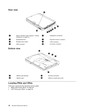
Rear view 1 8 1 Status indicators (see Chapter 5 "Status 5 indicators" on page 41) 2 ExpressCard slot 6 3 Wireless radio switch 7 4 USB connector 8 Bottom view 1 2 3 4 5 76 DisplayPort connector External monitor connector USB connector ac power connector 2 3 1 1 Battery pack latches 3 2 Battery pack 4 Locating FRUs and CRUs This topic introduces the following service parts: • "Major FRUs and CRUs" on page 50 • "LCD FRUs and CRUs" on page 52 4 Docking connector Memory module slot cover 48 Hardware Maintenance Manual
Rear view 1 8 1 Status indicators (see Chapter 5 "Status 5 indicators" on page 41) 2 ExpressCard slot 6 3 Wireless radio switch 7 4 USB connector 8 Bottom view 1 2 3 4 5 76 DisplayPort connector External monitor connector USB connector ac power connector 2 3 1 1 Battery pack latches 3 2 Battery pack 4 Locating FRUs and CRUs This topic introduces the following service parts: • "Major FRUs and CRUs" on page 50 • "LCD FRUs and CRUs" on page 52 4 Docking connector Memory module slot cover 48 Hardware Maintenance Manual


