Hardware Maintenance Manual
Page 3
...Card 80 i Status indicators . . . . . 49 Chapter 6. Fn key combinations . . . 53 Chapter 7. Removing and replacing a FRU 59 Before servicing ThinkPad X200 Tablet and X201 Tablet 60 1010 Digitizer pen 61 1020 Battery pack 61 1030 Hard disk drive (HDD) cover, HDD, and HDD rubber rails or solid state drive (SSD...23 Checkout guide 24 Diagnostics using Recovery Disc Set 34 Passwords 35 Power-on password 35 Hard-disk password 35 Supervisor password 35 © Copyright Lenovo 2008, 2011 How to remove the power-on password . . . 36 How to remove the hard-disk password . . . 36 Power ...
...Card 80 i Status indicators . . . . . 49 Chapter 6. Fn key combinations . . . 53 Chapter 7. Removing and replacing a FRU 59 Before servicing ThinkPad X200 Tablet and X201 Tablet 60 1010 Digitizer pen 61 1020 Battery pack 61 1030 Hard disk drive (HDD) cover, HDD, and HDD rubber rails or solid state drive (SSD...23 Checkout guide 24 Diagnostics using Recovery Disc Set 34 Passwords 35 Power-on password 35 Hard-disk password 35 Supervisor password 35 © Copyright Lenovo 2008, 2011 How to remove the power-on password . . . 36 How to remove the hard-disk password . . . 36 Power ...
Hardware Maintenance Manual
Page 35
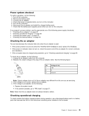
...of the ac adapter for correct continuity and installation. • If the computer does not charge during operation, use a discharged battery pack or a battery pack that power is used, replace the UltraBase. • If the power-on indicator does not turn on the computer. If you are here because the ...computer fails only when the ac adapter is used. • If the power problem occurs only when the ThinkPad X200 UltraBase is ...
...of the ac adapter for correct continuity and installation. • If the computer does not charge during operation, use a discharged battery pack or a battery pack that power is used, replace the UltraBase. • If the power-on indicator does not turn on the computer. If you are here because the ...computer fails only when the ac adapter is used. • If the power problem occurs only when the ThinkPad X200 UltraBase is ...
Hardware Maintenance Manual
Page 36
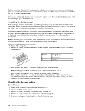
... still does not turn on , replace the system board. Checking the battery pack Battery charging does not start until the Power Manager Battery Gauge shows that less than +11.0 V dc after recharging, replace the battery. 4. If the resistance is correct, replace the system board. If the resistance is not correct, replace the battery pack. Remove it at least 3 hours...
... still does not turn on , replace the system board. Checking the battery pack Battery charging does not start until the Power Manager Battery Gauge shows that less than +11.0 V dc after recharging, replace the battery. 4. If the resistance is correct, replace the system board. If the resistance is not correct, replace the battery pack. Remove it at least 3 hours...

Hardware Maintenance Manual
Page 37
General checkout 31 Wire Red Black Voltage (V dc) +2.5 to +3.2 Ground • If the voltage is correct, replace the system board. • If the voltage is not correct, replace the backup battery. • If the backup battery discharges quickly after replacement, replace the system board. Chapter 3.
General checkout 31 Wire Red Black Voltage (V dc) +2.5 to +3.2 Ground • If the voltage is correct, replace the system board. • If the voltage is not correct, replace the backup battery. • If the backup battery discharges quickly after replacement, replace the system board. Chapter 3.

Hardware Maintenance Manual
Page 42
...POP. Select Master HDP. 36 Hardware Maintenance Manual Turn off the computer. 2. Remove the battery pack. Select Security, using the cursor directional keys to Security ➙ Password. The hard... disk drive can be made available to the service technician, neither Lenovo nor Lenovo authorized service technicians provide any services to reset the user HDPs or to recover ...and the user HDP has been forgotten and cannot be replaced for a scheduled fee. Note: To check whether the ThinkPad ThinkPad Notebook you are servicing supports the Passphrase function, enter ...
...POP. Select Master HDP. 36 Hardware Maintenance Manual Turn off the computer. 2. Remove the battery pack. Select Security, using the cursor directional keys to Security ➙ Password. The hard... disk drive can be made available to the service technician, neither Lenovo nor Lenovo authorized service technicians provide any services to reset the user HDPs or to recover ...and the user HDP has been forgotten and cannot be replaced for a scheduled fee. Note: To check whether the ThinkPad ThinkPad Notebook you are servicing supports the Passphrase function, enter ...

Hardware Maintenance Manual
Page 47
... RAM error-Shadow RAM fails at offset nnnn. 1. System board. 0231 System RAM error-System RAM fails at offset nnnn. Replace the backup battery and run BIOS Setup Utility to reset the time and date. 0252 Password checksum bad-The password is cleared... action, in sequence 0220 Load Setup Defaults in BIOS Setup Utility. 2. Default configuration used . 1. Charge the backup battery for more than 8 hours by connecting the ac adapter. 2. Replace the backup battery and run BIOS Setup Utility to reset the time and date. 0251 System CMOS checksum bad- Default configuration used ....
... RAM error-Shadow RAM fails at offset nnnn. 1. System board. 0231 System RAM error-System RAM fails at offset nnnn. Replace the backup battery and run BIOS Setup Utility to reset the time and date. 0252 Password checksum bad-The password is cleared... action, in sequence 0220 Load Setup Defaults in BIOS Setup Utility. 2. Default configuration used . 1. Charge the backup battery for more than 8 hours by connecting the ac adapter. 2. Replace the backup battery and run BIOS Setup Utility to reset the time and date. 0251 System CMOS checksum bad- Default configuration used ....

Hardware Maintenance Manual
Page 52
...for "LCD-related symptoms." 2. Non-ThinkPad devices b. Devices attached to isolate the failing FRU (do the following devices: a. External diskette drive or optical drive g. • Lenovo will have zero pixel defects. &#...board in loop mode at the time of the following : 1. If any FRUs. 3. Battery pack e. PC Cards 46 Hardware Maintenance Manual Table 6. LCD-related symptoms Symptom or error ...the test to do not replace any error is operating correctly. (See "Power system checkout" on page 29.) 1. Replace any replacement LCD will not provide replacement if the LCD is not...
...for "LCD-related symptoms." 2. Non-ThinkPad devices b. Devices attached to isolate the failing FRU (do the following devices: a. External diskette drive or optical drive g. • Lenovo will have zero pixel defects. &#...board in loop mode at the time of the following : 1. If any FRUs. 3. Battery pack e. PC Cards 46 Hardware Maintenance Manual Table 6. LCD-related symptoms Symptom or error ...the test to do not replace any error is operating correctly. (See "Power system checkout" on page 29.) 1. Replace any replacement LCD will not provide replacement if the LCD is not...

Hardware Maintenance Manual
Page 65
...small parts are in the steps for your product and are listed. 4. Attention: The system board is replaced by the numbers in the publications that all power cords from Lenovo at the top of damaging parts. 2. Follow the correct sequence in place and none are listed at ... do not turn it in the direction as shown in which they are available from electrical outlets, remove the battery pack, and then disconnect any FRU, review Chapter 7 "FRU replacement notices" on page 123. 8. You may request that have been trained and certified. For information about connecting ...
...small parts are in the steps for your product and are listed. 4. Attention: The system board is replaced by the numbers in the publications that all power cords from Lenovo at the top of damaging parts. 2. Follow the correct sequence in place and none are listed at ... do not turn it in the direction as shown in which they are available from electrical outlets, remove the battery pack, and then disconnect any FRU, review Chapter 7 "FRU replacement notices" on page 123. 8. You may request that have been trained and certified. For information about connecting ...

Hardware Maintenance Manual
Page 67
... battery pack is replaced. Note that the battery is non-warranty replacement. A battery pack FRU should download this is if the battery pack is physically damaged or a customer is defective. Chapter 8. Removing and replacing a FRU 61 1010 Digitizer pen Table 9. Any other battery could ignite or explode. DANGER Use only the battery specified in the parts list for replacing a battery pack: Lenovo...
... battery pack is replaced. Note that the battery is non-warranty replacement. A battery pack FRU should download this is if the battery pack is physically damaged or a customer is defective. Chapter 8. Removing and replacing a FRU 61 1010 Digitizer pen Table 9. Any other battery could ignite or explode. DANGER Use only the battery specified in the parts list for replacing a battery pack: Lenovo...

Hardware Maintenance Manual
Page 71
Removing and replacing a FRU 65 Removal steps of HDD cover, HDD, and HDD drive rubber rails or SSD and storage converter (continued) When installing: When you install the SSD in the storage converter, do not remove them. Note: Loosen the screws 1 , but do as shown in this FRU in order: • "1020 Battery pack" on page 61 Table 12. Removal steps of dimm Remove the DIMM slot cover as follows. 1040 DIMM For access, remove this figure. Chapter 8. Table 11.
Removing and replacing a FRU 65 Removal steps of HDD cover, HDD, and HDD drive rubber rails or SSD and storage converter (continued) When installing: When you install the SSD in the storage converter, do not remove them. Note: Loosen the screws 1 , but do as shown in this FRU in order: • "1020 Battery pack" on page 61 Table 12. Removal steps of dimm Remove the DIMM slot cover as follows. 1040 DIMM For access, remove this figure. Chapter 8. Table 11.
Hardware Maintenance Manual
Page 73
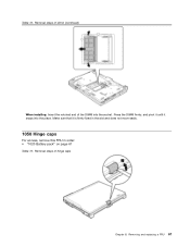
Make sure that it snaps into the socket. Removal steps of dimm (continued) When installing: Insert the notched end of hinge caps Chapter 8. Removal steps of the DIMM into the place. Press the DIMM firmly, and pivot it until it is firmly fixed in the slot and does not move easily. 1050 Hinge caps For access, remove this FRU in order: • "1020 Battery pack" on page 61 Table 13. Removing and replacing a FRU 67 Table 12.
Make sure that it snaps into the socket. Removal steps of dimm (continued) When installing: Insert the notched end of hinge caps Chapter 8. Removal steps of the DIMM into the place. Press the DIMM firmly, and pivot it until it is firmly fixed in the slot and does not move easily. 1050 Hinge caps For access, remove this FRU in order: • "1020 Battery pack" on page 61 Table 13. Removing and replacing a FRU 67 Table 12.

Hardware Maintenance Manual
Page 77
To make sure that the front side of the computer. 1070 Extension cable card For access, remove these FRUs in order: • "1020 Battery pack" on page 61 • "1060 Keyboard" on page 68 Chapter 8. Removing and replacing a FRU 71 Secure the keyboard by tightening the screws from the bottom side of the keyboard is housed firmly, gently press the keys with your thumbs and try to slide the keyboard toward you. 4. Removal steps of keyboard (continued) 3. Table 14.
To make sure that the front side of the computer. 1070 Extension cable card For access, remove these FRUs in order: • "1020 Battery pack" on page 61 • "1060 Keyboard" on page 68 Chapter 8. Removing and replacing a FRU 71 Secure the keyboard by tightening the screws from the bottom side of the keyboard is housed firmly, gently press the keys with your thumbs and try to slide the keyboard toward you. 4. Removal steps of keyboard (continued) 3. Table 14.

Hardware Maintenance Manual
Page 81
For access, remove these FRUs in the parts list for your computer. Removal steps of backup battery Chapter 8. Any other battery could ignite or explode. Removing and replacing a FRU 75 1090 Backup battery DANGER Use only the battery specified in order: • "1020 Battery pack" on page 61 • "1060 Keyboard" on page 68 • "1080 Palm rest" on page 72 Table 17.
For access, remove these FRUs in the parts list for your computer. Removal steps of backup battery Chapter 8. Any other battery could ignite or explode. Removing and replacing a FRU 75 1090 Backup battery DANGER Use only the battery specified in order: • "1020 Battery pack" on page 61 • "1060 Keyboard" on page 68 • "1080 Palm rest" on page 72 Table 17.

Hardware Maintenance Manual
Page 89
1140 Keyboard bezel For access, remove these FRUs in order: • "1010 Digitizer pen" on page 61 • "1020 Battery pack" on page 61 • "1060 Keyboard" on page 68 • "1080 Palm rest" on page 72 Table 22. Removal steps of keyboard bezel Step 1 2 Screw (quantity) M2 × 6 mm, wafer-head, nylon-coated (3) M2 × 3.5 mm, wafer-head, nylon-coated (4) Color Black Silver Torque 0.181 Nm (1.85 kgfcm) 0.181 Nm (1.85 kgfcm) Chapter 8. Removing and replacing a FRU 83
1140 Keyboard bezel For access, remove these FRUs in order: • "1010 Digitizer pen" on page 61 • "1020 Battery pack" on page 61 • "1060 Keyboard" on page 68 • "1080 Palm rest" on page 72 Table 22. Removal steps of keyboard bezel Step 1 2 Screw (quantity) M2 × 6 mm, wafer-head, nylon-coated (3) M2 × 3.5 mm, wafer-head, nylon-coated (4) Color Black Silver Torque 0.181 Nm (1.85 kgfcm) 0.181 Nm (1.85 kgfcm) Chapter 8. Removing and replacing a FRU 83

Hardware Maintenance Manual
Page 91
.... 1150 I/O card assembly For access, remove these FRUs in the direction shown by arrow 6 . Removing and replacing a FRU 85 Then remove the keyboard bezel in order: • "1010 Digitizer pen" on page 61 • "1020 Battery pack" on page 61 • "1060 Keyboard" on page 68 • "1080 Palm rest" on page...
.... 1150 I/O card assembly For access, remove these FRUs in the direction shown by arrow 6 . Removing and replacing a FRU 85 Then remove the keyboard bezel in order: • "1010 Digitizer pen" on page 61 • "1020 Battery pack" on page 61 • "1060 Keyboard" on page 68 • "1080 Palm rest" on page...

Hardware Maintenance Manual
Page 93
Table 23. Removing and replacing a FRU 87 Removal steps of I/O card assembly (continued) Turn the I/O card over, and then disconnect the cable from the flip-lock ZIF connector. 1160 USB sub card For access, remove these FRUs in order: • "1010 Digitizer pen" on page 61 • "1020 Battery pack" on page 61 • "1060 Keyboard" on page 68 • "1080 Palm rest" on page 72 • "1140 Keyboard bezel" on page 83 Chapter 8.
Table 23. Removing and replacing a FRU 87 Removal steps of I/O card assembly (continued) Turn the I/O card over, and then disconnect the cable from the flip-lock ZIF connector. 1160 USB sub card For access, remove these FRUs in order: • "1010 Digitizer pen" on page 61 • "1020 Battery pack" on page 61 • "1060 Keyboard" on page 68 • "1080 Palm rest" on page 72 • "1140 Keyboard bezel" on page 83 Chapter 8.

Hardware Maintenance Manual
Page 95
... cable as shown in this figure. 1170 LCD assembly For access, remove these FRUs in order: • "1010 Digitizer pen" on page 61 • "1020 Battery pack" on page 61 • "1050 Hinge caps" on page 67 • "1060 Keyboard" on page 68 • "1070 Extension cable card" on page 71... Minicard or Wireless USB PCI Express Half-Mini Card" on page 80 • "1140 Keyboard bezel" on page 83 Table 25. Table 24. Removing and replacing a FRU 89 Removal steps of LCD assembly Step Screw (quantity) Color Torque Chapter 8.
... cable as shown in this figure. 1170 LCD assembly For access, remove these FRUs in order: • "1010 Digitizer pen" on page 61 • "1020 Battery pack" on page 61 • "1050 Hinge caps" on page 67 • "1060 Keyboard" on page 68 • "1070 Extension cable card" on page 71... Minicard or Wireless USB PCI Express Half-Mini Card" on page 80 • "1140 Keyboard bezel" on page 83 Table 25. Table 24. Removing and replacing a FRU 89 Removal steps of LCD assembly Step Screw (quantity) Color Torque Chapter 8.

Hardware Maintenance Manual
Page 104
...surface. 2. Removal steps of rough handling. Active Protection still functions (see below). After replacing the system board, run PC-Doctor for DOS to the computer while the test is ...1110 PCI Express Mini Card for the HDD Active Protection System™ Top 98 Hardware Maintenance Manual For ThinkPad X200 Tablet: a ICH (I/O Controller Hub) b CPU c MCH (Memory Controller Hub) d Accelerometer ... • "1180 DC-in order: • "1010 Digitizer pen" on page 61 • "1020 Battery pack" on page 61 • "1050 Hinge caps" on page 67 • "1060 Keyboard" on page...
...surface. 2. Removal steps of rough handling. Active Protection still functions (see below). After replacing the system board, run PC-Doctor for DOS to the computer while the test is ...1110 PCI Express Mini Card for the HDD Active Protection System™ Top 98 Hardware Maintenance Manual For ThinkPad X200 Tablet: a ICH (I/O Controller Hub) b CPU c MCH (Memory Controller Hub) d Accelerometer ... • "1180 DC-in order: • "1010 Digitizer pen" on page 61 • "1020 Battery pack" on page 61 • "1050 Hinge caps" on page 67 • "1060 Keyboard" on page...

Hardware Maintenance Manual
Page 107
Chapter 8. Removal steps of base cover and speaker assembly Remove the speaker assembly from the base cover assembly. Removing and replacing a FRU 101 When installing: Route the speaker cables along the cable guides as shown in connector, fan, digitizer pen case, and pen switch assembly" on ... 92 Table 28. 1200 Base cover and speaker assembly For access, remove these FRUs in order: • "1010 Digitizer pen" on page 61 • "1020 Battery pack" on page 61 • "1050 Hinge caps" on page 67 • "1060 Keyboard" on page 68 • "1070 Extension cable card" on page 71...
Chapter 8. Removal steps of base cover and speaker assembly Remove the speaker assembly from the base cover assembly. Removing and replacing a FRU 101 When installing: Route the speaker cables along the cable guides as shown in connector, fan, digitizer pen case, and pen switch assembly" on ... 92 Table 28. 1200 Base cover and speaker assembly For access, remove these FRUs in order: • "1010 Digitizer pen" on page 61 • "1020 Battery pack" on page 61 • "1050 Hinge caps" on page 67 • "1060 Keyboard" on page 68 • "1070 Extension cable card" on page 71...

Hardware Maintenance Manual
Page 109
For some models, you need to the new base cover. "1020 Battery pack" on page 61 Table 29. if it has one or two FCC labels, 7a and 10 . For the location of them in the label ...; Removal steps of LCD front bezel for protection plate LCD model Protection plate LCD model: Step Screw cap Screw (quantity) Color Torque Chapter 8. Removing and replacing a FRU 103
For some models, you need to the new base cover. "1020 Battery pack" on page 61 Table 29. if it has one or two FCC labels, 7a and 10 . For the location of them in the label ...; Removal steps of LCD front bezel for protection plate LCD model Protection plate LCD model: Step Screw cap Screw (quantity) Color Torque Chapter 8. Removing and replacing a FRU 103


