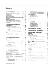
Hardware Maintenance Manual
Page 1
Hardware Maintenance Manual ThinkPad X200, X200s, X200si, X201, X201i, and X201s
Hardware Maintenance Manual ThinkPad X200, X200s, X200si, X201, X201i, and X201s
Hardware Maintenance Manual
Page 3
... hard disk drive . . . 30 Important notice for replacing a system board 30 How to do first 33 Checkout guide 34 System supporting the Lenovo ThinkVantage Toolbox program and the PC-Doctor for CTO, CMV, and GAV products 31 Chapter 3. Safety information 1 General safety 1 Electrical safety 2...No-beep symptoms 56 LCD-related symptoms 56 Intermittent problems 57 Undetermined problems 57 Chapter 5. Removing and replacing a FRU 69 Before servicing ThinkPad X200, X200s, X200si, X201, X201i, and X201s 70 1010 Battery pack 71 1020 Hard disk drive (HDD) cover, HDD, and HDD rubber rails...
... hard disk drive . . . 30 Important notice for replacing a system board 30 How to do first 33 Checkout guide 34 System supporting the Lenovo ThinkVantage Toolbox program and the PC-Doctor for CTO, CMV, and GAV products 31 Chapter 3. Safety information 1 General safety 1 Electrical safety 2...No-beep symptoms 56 LCD-related symptoms 56 Intermittent problems 57 Undetermined problems 57 Chapter 5. Removing and replacing a FRU 69 Before servicing ThinkPad X200, X200s, X200si, X201, X201i, and X201s 70 1010 Battery pack 71 1020 Hard disk drive (HDD) cover, HDD, and HDD rubber rails...
Hardware Maintenance Manual
Page 4
...-bit) DVDs . . . 262 Windows 7 Professional (64-bit) DVDs . . . 265 Windows 7 Starter (32-bit) DVDs 266 Common service tools 267 Appendix A. 1110 Monaural speaker assembly (for X200, X200s, X201s, and X201si 89 1120 I/O card assembly 90 1130 LCD assembly 92 1140 Base cover assembly and stereo speaker assembly for X201 and X201i 95..., DC-in . Parts list 135 Overall 136 LCD FRUs 220 12.1-in. Locations 131 Front view 131 Rear view 132 Bottom view 133 Rear view (ThinkPad X200 UltraBase 133 Bottom view (ThinkPad X200 UltraBase). . . . . 134 Chapter 10.
...-bit) DVDs . . . 262 Windows 7 Professional (64-bit) DVDs . . . 265 Windows 7 Starter (32-bit) DVDs 266 Common service tools 267 Appendix A. 1110 Monaural speaker assembly (for X200, X200s, X201s, and X201si 89 1120 I/O card assembly 90 1130 LCD assembly 92 1140 Base cover assembly and stereo speaker assembly for X201 and X201i 95..., DC-in . Parts list 135 Overall 136 LCD FRUs 220 12.1-in. Locations 131 Front view 131 Rear view 132 Bottom view 133 Rear view (ThinkPad X200 UltraBase 133 Bottom view (ThinkPad X200 UltraBase). . . . . 134 Chapter 10.

Hardware Maintenance Manual
Page 5
About this manual along with ThinkPad products. Before servicing a ThinkPad product, be sure to troubleshoot problems effectively. ThinkPad X200 ThinkPad X200s and X200si ThinkPad X201 and X201i ThinkPad X201s MT 7454, 7455, 7457, 7458, 7459, 2023, and 2024 MT 7462, 7465, 7466, 7469, 7470, 2046, and ...under Chapter 1 "Safety information" on page 1 and Chapter 2 "Important service information" on page 29. © Copyright Lenovo , 2011 iii Use this manual along with the advanced diagnostic tests to troubleshoot problems. Important: This manual is intended only for the following...
About this manual along with ThinkPad products. Before servicing a ThinkPad product, be sure to troubleshoot problems effectively. ThinkPad X200 ThinkPad X200s and X200si ThinkPad X201 and X201i ThinkPad X201s MT 7454, 7455, 7457, 7458, 7459, 2023, and 2024 MT 7462, 7465, 7466, 7469, 7470, 2046, and ...under Chapter 1 "Safety information" on page 1 and Chapter 2 "Important service information" on page 29. © Copyright Lenovo , 2011 iii Use this manual along with the advanced diagnostic tests to troubleshoot problems. Important: This manual is intended only for the following...

Hardware Maintenance Manual
Page 44
If the ThinkPad X200 Ultrabase™ is disabled, select Automatic to the ThinkPad computer, detach it . In this case, turn on the computer. Insert a PCI-Express/USB Wrap card into the ExpressCard slot. 2. Diagnostics ➙ Systemboard... also diagnose the hard disk drive without starting up the operating system. This symptom is running. Diagnostics ➙ Systemboard ➙ PCMCIA 1. Diagnostics ➙ ThinkPad Devices ➙ AC Adapter, Battery 1 (Battery2) 1. Interactive Tests ➙ Keyboard Enter the BIOS Setup Utility and change Serial ATA (SATA) setting to...
If the ThinkPad X200 Ultrabase™ is disabled, select Automatic to the ThinkPad computer, detach it . In this case, turn on the computer. Insert a PCI-Express/USB Wrap card into the ExpressCard slot. 2. Diagnostics ➙ Systemboard... also diagnose the hard disk drive without starting up the operating system. This symptom is running. Diagnostics ➙ Systemboard ➙ PCMCIA 1. Diagnostics ➙ ThinkPad Devices ➙ AC Adapter, Battery 1 (Battery2) 1. Interactive Tests ➙ Keyboard Enter the BIOS Setup Utility and change Serial ATA (SATA) setting to...

Hardware Maintenance Manual
Page 47
...during operation, go to "Checking operational charging" on page 37. If the voltage is used . • If the power problem occurs only when the ThinkPad X200 UltraBase is acceptable, do the following : 1. Use the arrow keys to use the diagnostic program. The diagnostic program will be launched automatically. 6. Remove.... • If the power-on indicator does not turn on the screen to select ATAPI CDx (x: 0, 1, ...) and then press Enter. When the ThinkPad logo is displayed, repeatedly press and release the F12 key. Connect the ac adapter. 4. 4. General checkout 41
...during operation, go to "Checking operational charging" on page 37. If the voltage is used . • If the power problem occurs only when the ThinkPad X200 UltraBase is acceptable, do the following : 1. Use the arrow keys to use the diagnostic program. The diagnostic program will be launched automatically. 6. Remove.... • If the power-on indicator does not turn on the screen to select ATAPI CDx (x: 0, 1, ...) and then press Enter. When the ThinkPad logo is displayed, repeatedly press and release the F12 key. Connect the ac adapter. 4. 4. General checkout 41
Hardware Maintenance Manual
Page 70
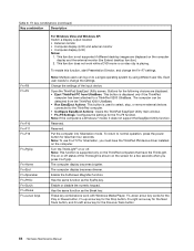
...Has the same function as the SysRq key. This function is displayed only if the ThinkPad computer has been attached to change the Fn+F7 settings. Each user needs to a ThinkPad X200 UltraBase. Note: Multiple users can be detached from UltraBase: This button is not supported ...if different desktop images are displayed on or off . Buttons for the following choices are displayed: • Eject ThinkPad PC from the ThinkPad X200 UltraBase. • Run EasyEject Actions: This button is shown on or off status of the input device. Reserved. This function...
...Has the same function as the SysRq key. This function is displayed only if the ThinkPad computer has been attached to change the Fn+F7 settings. Each user needs to a ThinkPad X200 UltraBase. Note: Multiple users can be detached from UltraBase: This button is not supported ...if different desktop images are displayed on or off . Buttons for the following choices are displayed: • Eject ThinkPad PC from the ThinkPad X200 UltraBase. • Run EasyEject Actions: This button is shown on or off status of the input device. Reserved. This function...

Hardware Maintenance Manual
Page 76
When disconnecting the cable from those connectors, do as shown in the ThinkPad X200, X200s, X200si, X201, X201i, and X201s are connected to remove the battery pack first. (See "1010 Battery pack" on disconnecting the cable from flip-lock ZIF connector: .... If the computer you are servicing has the SIM card, remove it before you start the servicing. Before servicing ThinkPad X200, X200s, X200si, X201, X201i, and X201s Removing the SIM card: Some models of the ThinkPad X200, X200s, X200si, X201, X201i, and X201s you are servicing might have the SIM card that you insert the card back into...
When disconnecting the cable from those connectors, do as shown in the ThinkPad X200, X200s, X200si, X201, X201i, and X201s are connected to remove the battery pack first. (See "1010 Battery pack" on disconnecting the cable from flip-lock ZIF connector: .... If the computer you are servicing has the SIM card, remove it before you start the servicing. Before servicing ThinkPad X200, X200s, X200si, X201, X201i, and X201s Removing the SIM card: Some models of the ThinkPad X200, X200s, X200si, X201, X201i, and X201s you are servicing might have the SIM card that you insert the card back into...

Hardware Maintenance Manual
Page 81
Removing and replacing a FRU 75 Removal steps of dimm Remove the DIMM slot cover as shown in SLOT-1 ( b ). Note: Loosen the screws 1 , but do not remove them. 2 1 1 Note: For ThinkPad X200, X200s, and X200si, if only one DIMM is used on the computer you are servicing, the card must be installed in SLOT-0 ( a ), but not in this figure. For ThinkPad X200, X200s, and X200si: Chapter 8. Table 11.
Removing and replacing a FRU 75 Removal steps of dimm Remove the DIMM slot cover as shown in SLOT-1 ( b ). Note: Loosen the screws 1 , but do not remove them. 2 1 1 Note: For ThinkPad X200, X200s, and X200si, if only one DIMM is used on the computer you are servicing, the card must be installed in SLOT-0 ( a ), but not in this figure. For ThinkPad X200, X200s, and X200si: Chapter 8. Table 11.

Hardware Maintenance Manual
Page 101
...)" on page 89 • "1120 I/O card assembly" on page 90 • "1130 LCD assembly" on page 88 • "1110 Monaural speaker assembly (for ThinkPad X200, X201, and X201i ThinkPad X200, X201, and X201 Remove the top shielding assembly at first. 1140 Base cover assembly and stereo speaker assembly for X201 and X201i For access...
...)" on page 89 • "1120 I/O card assembly" on page 90 • "1130 LCD assembly" on page 88 • "1110 Monaural speaker assembly (for ThinkPad X200, X201, and X201i ThinkPad X200, X201, and X201 Remove the top shielding assembly at first. 1140 Base cover assembly and stereo speaker assembly for X201 and X201i For access...

Hardware Maintenance Manual
Page 102
Removal steps of base cover assembly for ThinkPad X200, X201, and X201i (continued) Step 3 Screw (quantity) M2 × 3.5 mm, wafer-head, nylon-coated (1) Color Black Torque 0.181 Nm (1.85 kgfcm) Note: Step 4a is only for X201 and X201i. Step Screw (quantity) 4 M2 × 3.5 mm, wafer-head, nylon-coated (3) 4a M2 × 3.5 mm, wafer-head, nylon-coated (1) Color Silver Silver Torque 0.181 Nm (1.85 kgfcm) 0.181 Nm (1.85 kgfcm) 96 Hardware Maintenance Manual Table 22.
Removal steps of base cover assembly for ThinkPad X200, X201, and X201i (continued) Step 3 Screw (quantity) M2 × 3.5 mm, wafer-head, nylon-coated (1) Color Black Torque 0.181 Nm (1.85 kgfcm) Note: Step 4a is only for X201 and X201i. Step Screw (quantity) 4 M2 × 3.5 mm, wafer-head, nylon-coated (3) 4a M2 × 3.5 mm, wafer-head, nylon-coated (1) Color Silver Silver Torque 0.181 Nm (1.85 kgfcm) 0.181 Nm (1.85 kgfcm) 96 Hardware Maintenance Manual Table 22.

Hardware Maintenance Manual
Page 103
When installing: Check the position of base cover assembly for ThinkPad X201 and X201i. Removing and replacing a FRU 97 Cable routing: Route the speaker cable as shown in connector, and the fan assembly together from the base cover assembly. Removal steps of the wireless switch a , and firmly fit the system board into the base cover assembly. Chapter 8. Note: Following step is only for ThinkPad X200, X201, and X201i (continued) In step 5 and 6 , remove the system board, the DC-in this figure. Table 22.
When installing: Check the position of base cover assembly for ThinkPad X201 and X201i. Removing and replacing a FRU 97 Cable routing: Route the speaker cable as shown in connector, and the fan assembly together from the base cover assembly. Removal steps of the wireless switch a , and firmly fit the system board into the base cover assembly. Chapter 8. Note: Following step is only for ThinkPad X200, X201, and X201i (continued) In step 5 and 6 , remove the system board, the DC-in this figure. Table 22.

Hardware Maintenance Manual
Page 104
Removal steps of base cover assembly for ThinkPad X200s, X200si, and X201s ThinPad X200s, X200si and X201s Remove the top shielding assembly at first. 2 1 Step 1 Screw (quantity) M2 × 3 mm, wafer-head, nylon-coated (1) Color Black 3 Torque 0.181 Nm (1.85 kgfcm) Step 3 Screw (quantity) M2 × 3.5 mm, wafer-head, nylon-coated (1) Color Black Torque 0.181 Nm (1.85 kgfcm) 98 Hardware Maintenance Manual Table 23.
Removal steps of base cover assembly for ThinkPad X200s, X200si, and X201s ThinPad X200s, X200si and X201s Remove the top shielding assembly at first. 2 1 Step 1 Screw (quantity) M2 × 3 mm, wafer-head, nylon-coated (1) Color Black 3 Torque 0.181 Nm (1.85 kgfcm) Step 3 Screw (quantity) M2 × 3.5 mm, wafer-head, nylon-coated (1) Color Black Torque 0.181 Nm (1.85 kgfcm) 98 Hardware Maintenance Manual Table 23.

Hardware Maintenance Manual
Page 105
Removal steps of base cover assembly for ThinkPad X200s, X200si, and X201s (continued) 4 4 45 4 Step 4 5 Screw (quantity) M2 × 3.5 mm, wafer-head, nylon-coated (4) M2 × 3 mm, large-head, nylon-coated (1) Color Silver Silver Torque 0.181 Nm (1.85 kgfcm) 0.181 Nm (1.85 kgfcm) In step 6 and 7 , remove the system board, the DC-in the figure a . Removing and replacing a FRU 99 Table 23. Chapter 8. a 6 7 When installing: Attach the wireless radio switch as shown in connector, and the fan assembly together from the base cover assembly.
Removal steps of base cover assembly for ThinkPad X200s, X200si, and X201s (continued) 4 4 45 4 Step 4 5 Screw (quantity) M2 × 3.5 mm, wafer-head, nylon-coated (4) M2 × 3 mm, large-head, nylon-coated (1) Color Silver Silver Torque 0.181 Nm (1.85 kgfcm) 0.181 Nm (1.85 kgfcm) In step 6 and 7 , remove the system board, the DC-in the figure a . Removing and replacing a FRU 99 Table 23. Chapter 8. a 6 7 When installing: Attach the wireless radio switch as shown in connector, and the fan assembly together from the base cover assembly.

Hardware Maintenance Manual
Page 108
When you service the system board, avoid any kind of system board, DC-in connector, fan, and ExpressCard slot assembly for ThinkPad X200, X201, and X201i Following components soldered on page 95 Table 24. • "1130 LCD assembly" on page 92 •... Base cover assembly and stereo speaker assembly for X201 and X201i" on the system board are extremely sensitive. Removal steps of rough handling. ThinkPad X200 a Accelerometer chip for the HDD Active Protection SystemTM b ICH (I/O Controller Hub) c CPU d MCH (Memory Controller Hub) Top Bottom a b c d...
When you service the system board, avoid any kind of system board, DC-in connector, fan, and ExpressCard slot assembly for ThinkPad X200, X201, and X201i Following components soldered on page 95 Table 24. • "1130 LCD assembly" on page 92 •... Base cover assembly and stereo speaker assembly for X201 and X201i" on the system board are extremely sensitive. Removal steps of rough handling. ThinkPad X200 a Accelerometer chip for the HDD Active Protection SystemTM b ICH (I/O Controller Hub) c CPU d MCH (Memory Controller Hub) Top Bottom a b c d...

Hardware Maintenance Manual
Page 109
Removing and replacing a FRU 103 Table 24. Step 1 Screw (quantity) M2 × 3.5 mm, wafer-head, nylon-coated (1) Color Silver Torque 0.181 Nm (1.85 kgfcm) Chapter 8. Removal steps of system board, DC-in connector, fan, and ExpressCard slot assembly for ThinkPad X200, X201, and X201i (continued) ThinkPad X201 and X201i a CPU b PCH (Platform Controller Hub) c Accelerometer chip for the HDD Active Protection System Bottom a c b Note: The DC-in connector and the fan assembly are attached to the underside of the system board. 1 Note: Step 1 is only for ThinkPad X200.
Removing and replacing a FRU 103 Table 24. Step 1 Screw (quantity) M2 × 3.5 mm, wafer-head, nylon-coated (1) Color Silver Torque 0.181 Nm (1.85 kgfcm) Chapter 8. Removal steps of system board, DC-in connector, fan, and ExpressCard slot assembly for ThinkPad X200, X201, and X201i (continued) ThinkPad X201 and X201i a CPU b PCH (Platform Controller Hub) c Accelerometer chip for the HDD Active Protection System Bottom a c b Note: The DC-in connector and the fan assembly are attached to the underside of the system board. 1 Note: Step 1 is only for ThinkPad X200.

Hardware Maintenance Manual
Page 110
Removal steps of system board, DC-in connector, fan, and ExpressCard slot assembly for ThinkPad X200, X201, and X201i (continued) Turn the system board over, and then disconnect the DC-in connector and the fan connector from the system board. 2 3 When installing: Make sure that the DC-in connector and the fan connector are attached to the system board firmly. 4 4 4 5 6 Step 5 Screw (quantity) M2 × 3.5 mm, flat-head, nylon-coated (1) 104 Hardware Maintenance Manual Color Silver Torque 0.181 Nm (1.85 kgfcm) Table 24.
Removal steps of system board, DC-in connector, fan, and ExpressCard slot assembly for ThinkPad X200, X201, and X201i (continued) Turn the system board over, and then disconnect the DC-in connector and the fan connector from the system board. 2 3 When installing: Make sure that the DC-in connector and the fan connector are attached to the system board firmly. 4 4 4 5 6 Step 5 Screw (quantity) M2 × 3.5 mm, flat-head, nylon-coated (1) 104 Hardware Maintenance Manual Color Silver Torque 0.181 Nm (1.85 kgfcm) Table 24.

Hardware Maintenance Manual
Page 111
For ThinkPad X200: b a For ThinkPad X201 and X201i: b a • Make sure that the fan connector is attached to peel the thin film off from the rubber b . Removing and replacing a FRU ... in the following figure. You need to the system board. 1 Chapter 8. Removal steps of system board, DC-in connector, fan, and ExpressCard slot assembly for ThinkPad X200, X201, and X201i (continued) When installing: • Before you attach the fan assembly to the computer, apply thermal grease, at an amount of grease can...
For ThinkPad X200: b a For ThinkPad X201 and X201i: b a • Make sure that the fan connector is attached to peel the thin film off from the rubber b . Removing and replacing a FRU ... in the following figure. You need to the system board. 1 Chapter 8. Removal steps of system board, DC-in connector, fan, and ExpressCard slot assembly for ThinkPad X200, X201, and X201i (continued) When installing: • Before you attach the fan assembly to the computer, apply thermal grease, at an amount of grease can...

Hardware Maintenance Manual
Page 112
When you service the system board, avoid any kind of system board, DC-in connector, fan, and ExpressCard slot assembly for ThinkPad X200, X201, and X201i (continued) Step 1 Screw (quantity) M2 × 3.5 mm, flat-head, nylon-coated (1) Color Silver Torque 0....the system board. 2 3 Table 25. Table 24. Removal steps of system board, DC-in connector, fan, and ExpressCard slot assembly for ThinkPad X200s and X201s ThinkPad X200s Following components soldered on the system board are extremely sensitive. Removal steps of rough handling. a ICH (I/O Controller Hub) b CPU c MCH (...
When you service the system board, avoid any kind of system board, DC-in connector, fan, and ExpressCard slot assembly for ThinkPad X200, X201, and X201i (continued) Step 1 Screw (quantity) M2 × 3.5 mm, flat-head, nylon-coated (1) Color Silver Torque 0....the system board. 2 3 Table 25. Table 24. Removal steps of system board, DC-in connector, fan, and ExpressCard slot assembly for ThinkPad X200s and X201s ThinkPad X200s Following components soldered on the system board are extremely sensitive. Removal steps of rough handling. a ICH (I/O Controller Hub) b CPU c MCH (...

Hardware Maintenance Manual
Page 113
Removing and replacing a FRU 107 Removal steps of system board, DC-in connector, fan, and ExpressCard slot assembly for ThinkPad X200s and X201s (continued) Bottom d ThinkPad X201s a b c Bottom a b c CPU PCH (Platform Controller Hub) Accelerometer chip for the HDD Active Protection System Chapter 8. Table 25.
Removing and replacing a FRU 107 Removal steps of system board, DC-in connector, fan, and ExpressCard slot assembly for ThinkPad X200s and X201s (continued) Bottom d ThinkPad X201s a b c Bottom a b c CPU PCH (Platform Controller Hub) Accelerometer chip for the HDD Active Protection System Chapter 8. Table 25.


