
(English) Access Connections Profile Deployment guide
Page 21
v Enable auto deletion of unused profiles v Disable the Peer to Peer community feature Chapter 3. Working with the Administrator Feature 13 disabled even when the Ethernet cable is plugged in again. To re-enable the Ethernet port, manually apply the profile for the Ethernet connection.
v Enable auto deletion of unused profiles v Disable the Peer to Peer community feature Chapter 3. Working with the Administrator Feature 13 disabled even when the Ethernet cable is plugged in again. To re-enable the Ethernet port, manually apply the profile for the Ethernet connection.

(English) Access Connections Profile Deployment guide
Page 25
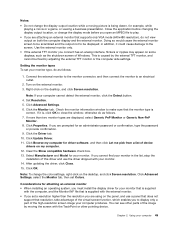
... and printer sharing v Start applications automatically v Set default printer v Override TCP/IP and DNS defaults v Enable VPN connection v Override Home page v Override Proxy Configurations Figure 13. Working with the Administrator Feature 17 Disable internet connection sharing Chapter 3. Default Options for Access Connections: General Options v Do not show warning message when connecting...
... and printer sharing v Start applications automatically v Set default printer v Override TCP/IP and DNS defaults v Enable VPN connection v Override Home page v Override Proxy Configurations Figure 13. Working with the Administrator Feature 17 Disable internet connection sharing Chapter 3. Default Options for Access Connections: General Options v Do not show warning message when connecting...

Hardware Maintenance Manual
Page 90
... two FCC labels. label 16 System label 18 FCC label For some models, you need to the following figure: 12 3 18 4 17 5 16 15 6 7 8 9 14 13 12 11 10 2010 LCD unit For access, disable the battery pack first. Refer to the new base cover. Check the old base cover; if... page 59 • "1020 Keyboard" on page 61 • "1090 Keyboard bezel assembly with fingerprint reader and audio sub card " on page 58 for Brazil) 13 Brazil WWAN label 14 Asset tag 15 Serial No. Then remove these FRUs in the UEFI BIOS" on page 71 84 Hardware Maintenance Manual 11...
... two FCC labels. label 16 System label 18 FCC label For some models, you need to the following figure: 12 3 18 4 17 5 16 15 6 7 8 9 14 13 12 11 10 2010 LCD unit For access, disable the battery pack first. Refer to the new base cover. Check the old base cover; if... page 59 • "1020 Keyboard" on page 61 • "1090 Keyboard bezel assembly with fingerprint reader and audio sub card " on page 58 for Brazil) 13 Brazil WWAN label 14 Asset tag 15 Serial No. Then remove these FRUs in the UEFI BIOS" on page 71 84 Hardware Maintenance Manual 11...

Hardware Maintenance Manual
Page 99
Front view 1 13 2 3 14 12 11 1 Integrated camera 2 Built-in microphone 3 Status indicators 4 5 6 7 8 9 10 Note: For the description of ThinkPad X1 and X1 Hybrid features and hardware. Locations This chapter presents the location of each indicator, see Chapter 5 "Status indicators" on page 47. 4 Power switch 5...7 4-in-1 Media Card Reader 8 Built-in stereo speaker (right) 9 Wireless radio switch 10 Fingerprint reader 11 Touch pad 12 TrackPoint buttons 13 TrackPoint pointing stick 14 UltraNav® pointing device © Copyright Lenovo 2011, 2012 93 Chapter 9.
Front view 1 13 2 3 14 12 11 1 Integrated camera 2 Built-in microphone 3 Status indicators 4 5 6 7 8 9 10 Note: For the description of ThinkPad X1 and X1 Hybrid features and hardware. Locations This chapter presents the location of each indicator, see Chapter 5 "Status indicators" on page 47. 4 Power switch 5...7 4-in-1 Media Card Reader 8 Built-in stereo speaker (right) 9 Wireless radio switch 10 Fingerprint reader 11 Touch pad 12 TrackPoint buttons 13 TrackPoint pointing stick 14 UltraNav® pointing device © Copyright Lenovo 2011, 2012 93 Chapter 9.

Hardware Maintenance Manual
Page 100
Rear view 13 12 11 10 9 8 7 6 5 1 2 3 4 1 Built-in stereo speaker (left) 2 USB connector (left) 3 Combo audio jack 4 Fan louvers 5 Security keyhole 6 Power jack 7 eSATA/Always on USB combo connector (rear) 8 Mini DisplayPort connector 9 HDMI port 10 USB connector (rear) 11 SIM card slot 12 Status indicators Note: For the description of each indicator, see Chapter 5 "Status indicators" on page 47. 13 RJ-45 (Ethernet) connector 94 Hardware Maintenance Manual
Rear view 13 12 11 10 9 8 7 6 5 1 2 3 4 1 Built-in stereo speaker (left) 2 USB connector (left) 3 Combo audio jack 4 Fan louvers 5 Security keyhole 6 Power jack 7 eSATA/Always on USB combo connector (rear) 8 Mini DisplayPort connector 9 HDMI port 10 USB connector (rear) 11 SIM card slot 12 Status indicators Note: For the description of each indicator, see Chapter 5 "Status indicators" on page 47. 13 RJ-45 (Ethernet) connector 94 Hardware Maintenance Manual

Hardware Maintenance Manual
Page 104
Overall 1 18 17 2 16 3 15 4 14 a 5 13 6 c 7 12 8 b 9 11 10 98 Hardware Maintenance Manual
Overall 1 18 17 2 16 3 15 4 14 a 5 13 6 c 7 12 8 b 9 11 10 98 Hardware Maintenance Manual

Hardware Maintenance Manual
Page 109
...; 1292-CTO • 1293-CTO • 1294-CTO • 1295-CTO • 1296-CTO 63Y1676 04W3536 13 System board assembly, Intel Core i5-2520M AMT, Non-TPM, Non-AES • 1286-CTO • 1291-...; 1293-CTO, 3Jx, 3Kx, 3Lx • 1294-CTO • 1295-CTO • 1296-CTO 63Y1677 04W3542 13 System board assembly, Intel Core i5-2520M Non-AMT, TPM, AES • 1286-CTO • 1291-CTO &#...8226; 1292-CTO • 1293-CTO • 1294-CTO • 1295-CTO • 1296-CTO 63Y1679 04W3545 13 System board assembly, Intel Core i3-2310M TPM, Non-AES 63Y1684 • 1286-CTO, 35x, 37x, 38x •...
...; 1292-CTO • 1293-CTO • 1294-CTO • 1295-CTO • 1296-CTO 63Y1676 04W3536 13 System board assembly, Intel Core i5-2520M AMT, Non-TPM, Non-AES • 1286-CTO • 1291-...; 1293-CTO, 3Jx, 3Kx, 3Lx • 1294-CTO • 1295-CTO • 1296-CTO 63Y1677 04W3542 13 System board assembly, Intel Core i5-2520M Non-AMT, TPM, AES • 1286-CTO • 1291-CTO &#...8226; 1292-CTO • 1293-CTO • 1294-CTO • 1295-CTO • 1296-CTO 63Y1679 04W3545 13 System board assembly, Intel Core i3-2310M TPM, Non-AES 63Y1684 • 1286-CTO, 35x, 37x, 38x •...

Hardware Maintenance Manual
Page 110
...; 1291-CTO • 1292-CTO • 1293-CTO • 1294-CTO • 1295-CTO • 1296-CTO 13 System board assembly, Intel Core i7-2620M AMT, TPM, AES • 1286-CTO • 1291-CTO • 1292-...CTO • 1293-CTO • 1294-CTO • 1295-CTO • 1296-CTO 13 System board assembly, Intel Core i7-2620M Non-AMT, TPM, AES • 1286-CTO • 1291-CTO •...3Rx • 1292-CTO • 1293-CTO, 2Sx • 1294-CTO • 1295-CTO • 1296-CTO 13 System board assembly, Intel Core i7-2620M Non-AMT, Non-TPM, Non-AES • 1286-CTO, 3Ax, 3Bx &#...
...; 1291-CTO • 1292-CTO • 1293-CTO • 1294-CTO • 1295-CTO • 1296-CTO 13 System board assembly, Intel Core i7-2620M AMT, TPM, AES • 1286-CTO • 1291-CTO • 1292-...CTO • 1293-CTO • 1294-CTO • 1295-CTO • 1296-CTO 13 System board assembly, Intel Core i7-2620M Non-AMT, TPM, AES • 1286-CTO • 1291-CTO •...3Rx • 1292-CTO • 1293-CTO, 2Sx • 1294-CTO • 1295-CTO • 1296-CTO 13 System board assembly, Intel Core i7-2620M Non-AMT, Non-TPM, Non-AES • 1286-CTO, 3Ax, 3Bx &#...

Hardware Maintenance Manual
Page 111
...• 1292-CTO • 1293-CTO • 1294-CTO • 1295-CTO • 1296-CTO 04W3473 04W3537 13 System board assembly, Intel Core i7-2640M, Non-AMT, TPM, AES • 1286-CTO • 1291-CTO ...• 1292-CTO • 1293-CTO • 1294-CTO • 1295-CTO • 1296-CTO 04W3474 04W3540 13 System board assembly, Intel Core i7-2640M, AMT, Non-TPM, Non-AES • 1286-CTO, 2Jx, 2Nx,...8226; 1292-CTO • 1293-CTO • 1294-CTO • 1295-CTO • 1296-CTO 04W3475 04W3543 13 System board assembly, Intel Core i7-2640M, Non-AMT, Non-TPM, Non-AES • 1286-CTO •...
...• 1292-CTO • 1293-CTO • 1294-CTO • 1295-CTO • 1296-CTO 04W3473 04W3537 13 System board assembly, Intel Core i7-2640M, Non-AMT, TPM, AES • 1286-CTO • 1291-CTO ...• 1292-CTO • 1293-CTO • 1294-CTO • 1295-CTO • 1296-CTO 04W3474 04W3540 13 System board assembly, Intel Core i7-2640M, AMT, Non-TPM, Non-AES • 1286-CTO, 2Jx, 2Nx,...8226; 1292-CTO • 1293-CTO • 1294-CTO • 1295-CTO • 1296-CTO 04W3475 04W3543 13 System board assembly, Intel Core i7-2640M, Non-AMT, Non-TPM, Non-AES • 1286-CTO •...

Hardware Maintenance Manual
Page 115
... Netherlands Norwegian Polish Portuguese Russian Slovak Slovenia Spanish Swiss Thai Traditional Chinese Turkish UK English US English US English International Turkish (F Type) Miscellaneous parts Table 13. Parts list-Miscellaneous parts FRU Base miscellaneous kit • Battery Door • DCIN Lens • DCIN Cable • DCIN Bracket FRU No. 04W2783 04W2768 04W2769...
... Netherlands Norwegian Polish Portuguese Russian Slovak Slovenia Spanish Swiss Thai Traditional Chinese Turkish UK English US English US English International Turkish (F Type) Miscellaneous parts Table 13. Parts list-Miscellaneous parts FRU Base miscellaneous kit • Battery Door • DCIN Lens • DCIN Cable • DCIN Bracket FRU No. 04W2783 04W2768 04W2769...

Hardware Maintenance Manual
Page 116
Cable kit for X1 and X1 Hybrid • (b) Bluetooth sub card • (c) I /O Door • Knob for Wireless Switch Black • Knob for Wireless Switch Green • Rubber Foot Front • Rubber Foot Rear • SIM Door • Mesh Sheet for X1 • (b) Bluetooth sub card • (c) I/O cable ...• Audio board flat cable Note: Italicized letters in parentheses are references to the exploded view in "Overall" on page 98. Table 13. Seal kit • Screw Cap Long •...
Cable kit for X1 and X1 Hybrid • (b) Bluetooth sub card • (c) I /O Door • Knob for Wireless Switch Black • Knob for Wireless Switch Green • Rubber Foot Front • Rubber Foot Rear • SIM Door • Mesh Sheet for X1 • (b) Bluetooth sub card • (c) I/O cable ...• Audio board flat cable Note: Italicized letters in parentheses are references to the exploded view in "Overall" on page 98. Table 13. Seal kit • Screw Cap Long •...

(English) User Guide
Page 3
...Locating important product information . . . . . 12 Machine type and model label 12 FCC ID and IC Certification number label . . 13 Certificate of the UltraNav and an external mouse 34 Adding the UltraNav icon to the network 37 Ethernet connections 37 Wireless connections 38 Using an.... . . . 17 Access Connections 19 Active Protection System 19 Client Security Solution 19 Fingerprint Software 19 Lenovo Solution Center 19 Lenovo ThinkVantage Tools 20 Lenovo ThinkVantage Toolbox 20 Message Center Plus 20 Password Manager 20 Power Manager 20 Product Recovery 21 Rescue and Recovery...
...Locating important product information . . . . . 12 Machine type and model label 12 FCC ID and IC Certification number label . . 13 Certificate of the UltraNav and an external mouse 34 Adding the UltraNav icon to the network 37 Ethernet connections 37 Wireless connections 38 Using an.... . . . 17 Access Connections 19 Active Protection System 19 Client Security Solution 19 Fingerprint Software 19 Lenovo Solution Center 19 Lenovo ThinkVantage Tools 20 Lenovo ThinkVantage Toolbox 20 Message Center Plus 20 Password Manager 20 Power Manager 20 Product Recovery 21 Rescue and Recovery...

(English) User Guide
Page 18
By using this camera, you can take pictures or hold a video conference. 2 User Guide ThinkPad X1 front view 1 3 UltraConnect wireless antennas The built-in microphone 7 Power switch 9 Volume control buttons 11 Fingerprint reader 13 PCI Express Mini Card slot for wireless WAN card, mSATA solid state drive, or Instant Media Mode card 15 TrackPoint...
By using this camera, you can take pictures or hold a video conference. 2 User Guide ThinkPad X1 front view 1 3 UltraConnect wireless antennas The built-in microphone 7 Power switch 9 Volume control buttons 11 Fingerprint reader 13 PCI Express Mini Card slot for wireless WAN card, mSATA solid state drive, or Instant Media Mode card 15 TrackPoint...

(English) User Guide
Page 20
On some models, an Instant Media Mode card is located under the right side of the palm rest. 13 PCI Express Mini Card slot for data storage. For details, refer to the instructions in "Using a fingerprint reader" on page 25. For more information, refer ...
On some models, an Instant Media Mode card is located under the right side of the palm rest. 13 PCI Express Mini Card slot for data storage. For details, refer to the instructions in "Using a fingerprint reader" on page 25. For more information, refer ...

(English) User Guide
Page 29
The FCC ID and IC Certification number label is no FCC ID or IC Certification number for the PCI Express Mini Card shown on the card installed in the Mini PCI Express Card slot of your computer. FCC ID and IC Certification number label There is affixed on the enclosure of your computer. Chapter 1. Product overview 13
The FCC ID and IC Certification number label is no FCC ID or IC Certification number for the PCI Express Mini Card shown on the card installed in the Mini PCI Express Card slot of your computer. FCC ID and IC Certification number label There is affixed on the enclosure of your computer. Chapter 1. Product overview 13

(English) User Guide
Page 31
... drive or 2.5-inch (7 mm height) solid state drive • mSATA solid state drive (on some models) Display The color display uses TFT technology: • Size: 13.3 inch (338 mm) • LCD resolution: up to 1366-by-768 • Brightness control • Integrated camera • Built-in digital dual array microphones •...
... drive or 2.5-inch (7 mm height) solid state drive • mSATA solid state drive (on some models) Display The color display uses TFT technology: • Size: 13.3 inch (338 mm) • LCD resolution: up to 1366-by-768 • Brightness control • Integrated camera • Built-in digital dual array microphones •...

(English) User Guide
Page 32
... of the AC adapter: 100 to 240 V AC, 50 to sunshine. Storage: 5% to 95% If possible, place your keyboard. Specifications Size • Width: 337 mm (13.3 inch) • Depth: 231.1 mm (9.1 inch) • Height: 16.5 to 21.3 mm (0.65 to 0.84 inch) Heat output • 90 W (307 Btu/hr) maximum Power...
... of the AC adapter: 100 to 240 V AC, 50 to sunshine. Storage: 5% to 95% If possible, place your keyboard. Specifications Size • Width: 337 mm (13.3 inch) • Depth: 231.1 mm (9.1 inch) • Height: 16.5 to 21.3 mm (0.65 to 0.84 inch) Heat output • 90 W (307 Btu/hr) maximum Power...
(English) User Guide
Page 61
... Screen resolution. Connect the external monitor to the monitor connector, and then connect the monitor to the screen. Clear the Show compatible hardware check box. 13. Close the application before changing the display output location, or change the display output location while a moving the screen with your computer cannot detect the...
... Screen resolution. Connect the external monitor to the monitor connector, and then connect the monitor to the screen. Clear the Show compatible hardware check box. 13. Close the application before changing the display output location, or change the display output location while a moving the screen with your computer cannot detect the...

(English) User Guide
Page 74
Press Enter once to move to the next line. Click Continue. 13. A new hard disk user password window opens. Click Continue. 16. ... HDP or Master HDP. Otherwise, if you cannot get access to verify it . 15. Press F10 to the ThinkPad Setup program. A Setup Notice window is required, and a fee will have the hard disk drive replaced. Retype ... that contains more than seven characters, you forget the user-only password, or both user and master passwords, Lenovo cannot reset your new password in a safe place. Type your passwords or recover data from the Setup Notice...
Press Enter once to move to the next line. Click Continue. 13. A new hard disk user password window opens. Click Continue. 16. ... HDP or Master HDP. Otherwise, if you cannot get access to verify it . 15. Press F10 to the ThinkPad Setup program. A Setup Notice window is required, and a fee will have the hard disk drive replaced. Retype ... that contains more than seven characters, you forget the user-only password, or both user and master passwords, Lenovo cannot reset your new password in a safe place. Type your passwords or recover data from the Setup Notice...

(English) User Guide
Page 118
.... 16. Confirm the correct display type, then click Next. 14. Click Close. 15. To start the ThinkPad Setup by the supervisor password. Click OK. 13. Windows has finished installing. Click OK and close the Display Settings window. Installing Intel Chipset Support for Windows 2000...will also need on page 55. To install it, go to: http://www.lenovo.com/ThinkPadDrivers ThinkPad Setup Your computer provides a program, called ThinkPad Setup, that are provided in the Monitor tab. 17. The ThinkPad Setup opens. When the logo screen is shown as follows: 1. To do ...
.... 16. Confirm the correct display type, then click Next. 14. Click Close. 15. To start the ThinkPad Setup by the supervisor password. Click OK. 13. Windows has finished installing. Click OK and close the Display Settings window. Installing Intel Chipset Support for Windows 2000...will also need on page 55. To install it, go to: http://www.lenovo.com/ThinkPadDrivers ThinkPad Setup Your computer provides a program, called ThinkPad Setup, that are provided in the Monitor tab. 17. The ThinkPad Setup opens. When the logo screen is shown as follows: 1. To do ...


