Hardware Maintenance Manual
Page 1
ThinkPad W700, W700ds, W701, and W701ds Hardware Maintenance Manual
ThinkPad W700, W700ds, W701, and W701ds Hardware Maintenance Manual
Hardware Maintenance Manual
Page 4
...ThinkPad W700ds 188 LCD FRUs for ThinkPad W701 189 LCD FRUs for ThinkPad W700ds and W701ds) . . 155 Rear view 156 Bottom view 157 Chapter 11. Notices 209 Trademarks 210 ii ThinkPad W700, W700ds, W701, and W701ds Hardware Maintenance Manual Locations 153 Front view (for ThinkPad W700 and W701) . . . . 153 Front view (for ThinkPad W701ds...Second LCD bezel (second LCD cover kit) (for ThinkPad W700ds and W701ds 138 2070 Second LCD panel (for ThinkPad W700ds and W701ds 140 2080 Second LCD cable assembly (for ThinkPad W700ds and W701ds 141 2090 Second LCD hinges and second LCD rear ...
...ThinkPad W700ds 188 LCD FRUs for ThinkPad W701 189 LCD FRUs for ThinkPad W700ds and W701ds) . . 155 Rear view 156 Bottom view 157 Chapter 11. Notices 209 Trademarks 210 ii ThinkPad W700, W700ds, W701, and W701ds Hardware Maintenance Manual Locations 153 Front view (for ThinkPad W700 and W701) . . . . 153 Front view (for ThinkPad W701ds...Second LCD bezel (second LCD cover kit) (for ThinkPad W700ds and W701ds 138 2070 Second LCD panel (for ThinkPad W700ds and W701ds 140 2080 Second LCD cable assembly (for ThinkPad W700ds and W701ds 141 2090 Second LCD hinges and second LCD rear ...
Hardware Maintenance Manual
Page 5
...information for trained service technicians who are familiar with ThinkPad products. Before servicing a ThinkPad product, be sure to troubleshooting problems effectively. ThinkPad W700 and W700ds MT 2752, 2753, 2754, 2757, 2758, 2762, and 2763 ThinkPad W701 and W701ds MT 2500, 2541, 2542, 2543, 2544, ...4323, and 4326 Use this manual along with the advanced diagnostic tests to read all the information under Chapter 1 "Safety information" on page 1 and Chapter 2 "Important service information" on page 25. © Copyright Lenovo ...
...information for trained service technicians who are familiar with ThinkPad products. Before servicing a ThinkPad product, be sure to troubleshooting problems effectively. ThinkPad W700 and W700ds MT 2752, 2753, 2754, 2757, 2758, 2762, and 2763 ThinkPad W701 and W701ds MT 2500, 2541, 2542, 2543, 2544, ...4323, and 4326 Use this manual along with the advanced diagnostic tests to read all the information under Chapter 1 "Safety information" on page 1 and Chapter 2 "Important service information" on page 25. © Copyright Lenovo ...

Hardware Maintenance Manual
Page 6
iv ThinkPad W700, W700ds, W701, and W701ds Hardware Maintenance Manual
iv ThinkPad W700, W700ds, W701, and W701ds Hardware Maintenance Manual

Hardware Maintenance Manual
Page 80
Make sure that it snaps into the socket. b a When installing:Insert the notched end of DIMM slot cover and DIMM (continued) Note: If only one DIMM is firmly fixed in SLOT-1 ( b ). Press the DIMM firmly, and pivot it until it is used on the computer you are servicing, the card must be installed in SLOT-0 ( a ), but not in the slot and does not move easily. For ThinkPad W701 and W701ds: 3 4 3 74 ThinkPad W700, W700ds, W701, and W701ds Hardware Maintenance Manual Table 13. Removal steps of the DIMM into the place.
Make sure that it snaps into the socket. b a When installing:Insert the notched end of DIMM slot cover and DIMM (continued) Note: If only one DIMM is firmly fixed in SLOT-1 ( b ). Press the DIMM firmly, and pivot it until it is used on the computer you are servicing, the card must be installed in SLOT-0 ( a ), but not in the slot and does not move easily. For ThinkPad W701 and W701ds: 3 4 3 74 ThinkPad W700, W700ds, W701, and W701ds Hardware Maintenance Manual Table 13. Removal steps of the DIMM into the place.
Hardware Maintenance Manual
Page 89
Table 19. Removal steps of backup battery (continued) For ThinkPad W701 and W701ds: 1 2 When installing: Make sure that the battery connector is attached firmly. 1110 Numeric keypad For access, remove these FRUs in order: • "1010 Battery pack" on page 68 • "1040 Hard disk drive (HDD) cover, HDD and HDD rubber rails or solid state drive (SSD) and storage converter" on page 70 • "1060 Palm rest or palm rest with fingerprint reader" on page 75 • "1090 Keyboard" on page 80 Chapter 9. Removing and replacing a FRU 83
Table 19. Removal steps of backup battery (continued) For ThinkPad W701 and W701ds: 1 2 When installing: Make sure that the battery connector is attached firmly. 1110 Numeric keypad For access, remove these FRUs in order: • "1010 Battery pack" on page 68 • "1040 Hard disk drive (HDD) cover, HDD and HDD rubber rails or solid state drive (SSD) and storage converter" on page 70 • "1060 Palm rest or palm rest with fingerprint reader" on page 75 • "1090 Keyboard" on page 80 Chapter 9. Removing and replacing a FRU 83

Hardware Maintenance Manual
Page 92
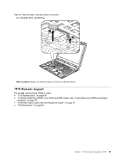
Removal steps of numeric keypad (continued) 2 a Note: For ThinkPad W701 and W701ds, make sure that the cable 3 is under the frame as shown in this figure. 3 1120 DIMM slot cover and DIMM under keyboard for W701 and W701ds For access, remove this FRU: • "1010 Battery pack" on page 68 • "1040 Hard disk drive (HDD... storage converter" on page 70 • "1060 Palm rest or palm rest with fingerprint reader" on page 75 • "1090 Keyboard" on page 80 86 ThinkPad W700, W700ds, W701, and W701ds Hardware Maintenance Manual Table 20.
Removal steps of numeric keypad (continued) 2 a Note: For ThinkPad W701 and W701ds, make sure that the cable 3 is under the frame as shown in this figure. 3 1120 DIMM slot cover and DIMM under keyboard for W701 and W701ds For access, remove this FRU: • "1010 Battery pack" on page 68 • "1040 Hard disk drive (HDD... storage converter" on page 70 • "1060 Palm rest or palm rest with fingerprint reader" on page 75 • "1090 Keyboard" on page 80 86 ThinkPad W700, W700ds, W701, and W701ds Hardware Maintenance Manual Table 20.

Hardware Maintenance Manual
Page 96
Removal steps of keyboard bezel for W700 and W700ds 1 1 1 2 Step 1 Screw (quantity) M2 × 3.5 mm, small-head, nylon-coated (3) Color Silver Table 24. Table 23. Removal steps of speaker assembly for W701 and W701ds For ThinkPad W701 and W701ds: 1 1 1 1 Torque 0.181 Nm (1.85 kgfcm) Step 1 Screw (quantity) M2.5 × 9 mm, wafer-head, nylon-coated (4) Color Black Torque 0.392 Nm (4 kgfcm) 90 ThinkPad W700, W700ds, W701, and W701ds Hardware Maintenance Manual
Removal steps of keyboard bezel for W700 and W700ds 1 1 1 2 Step 1 Screw (quantity) M2 × 3.5 mm, small-head, nylon-coated (3) Color Silver Table 24. Table 23. Removal steps of speaker assembly for W701 and W701ds For ThinkPad W701 and W701ds: 1 1 1 1 Torque 0.181 Nm (1.85 kgfcm) Step 1 Screw (quantity) M2.5 × 9 mm, wafer-head, nylon-coated (4) Color Black Torque 0.392 Nm (4 kgfcm) 90 ThinkPad W700, W700ds, W701, and W701ds Hardware Maintenance Manual

Hardware Maintenance Manual
Page 102
Removal steps of PCI Express Mini Card for wireless LAN/WiMAX for ThinkPad W701 and W701ds For ThinkPad W701 and W701ds: In step 1 , unplug the jacks by using the removal tool antenna RF connector (P/N: 08K7159) or pick the connectors with your fingers and gently unplug them .... Table 28. Removal steps of the arrow. 2 1 2 Step 2 Screw (quantity) M2 × 3 mm, thin-head, nylon-coated (2) 3 Color Black Torque 0.181 Nm (1.85 kgfcm) 96 ThinkPad W700, W700ds, W701, and W701ds Hardware Maintenance Manual Table 27.
Removal steps of PCI Express Mini Card for wireless LAN/WiMAX for ThinkPad W701 and W701ds For ThinkPad W701 and W701ds: In step 1 , unplug the jacks by using the removal tool antenna RF connector (P/N: 08K7159) or pick the connectors with your fingers and gently unplug them .... Table 28. Removal steps of the arrow. 2 1 2 Step 2 Screw (quantity) M2 × 3 mm, thin-head, nylon-coated (2) 3 Color Black Torque 0.181 Nm (1.85 kgfcm) 96 ThinkPad W700, W700ds, W701, and W701ds Hardware Maintenance Manual Table 27.
Hardware Maintenance Manual
Page 103
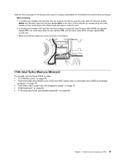
Removal steps of PCI Express Mini Card for wireless LAN/WiMAX for ThinkPad W701 and W701ds (continued) When installing: • In models with wireless LAN card that the cables are routed as shown in this figure. 1160 Intel Turbo Memory Minicard ...
Removal steps of PCI Express Mini Card for wireless LAN/WiMAX for ThinkPad W701 and W701ds (continued) When installing: • In models with wireless LAN card that the cables are routed as shown in this figure. 1160 Intel Turbo Memory Minicard ...

Hardware Maintenance Manual
Page 107
Removal steps of the fan can cause distortion or deformation and imperfect contact with components. 5 4 Chapter 9. When you attach the fan, secure the screws in order as shown in this figure. 1 2 3 Attention: Do not handle the fan roughly. Table 32. Improper handling of CPU thermal device/fan for W701 and W701ds For ThinkPad W701 and W701ds: Note: Loosen the screws 1 , 2 , and 3 , but do not remove them. Removing and replacing a FRU 101
Removal steps of the fan can cause distortion or deformation and imperfect contact with components. 5 4 Chapter 9. When you attach the fan, secure the screws in order as shown in this figure. 1 2 3 Attention: Do not handle the fan roughly. Table 32. Improper handling of CPU thermal device/fan for W701 and W701ds For ThinkPad W701 and W701ds: Note: Loosen the screws 1 , 2 , and 3 , but do not remove them. Removing and replacing a FRU 101

Hardware Maintenance Manual
Page 108
...the video card. For access, remove these FRUs in the video card FRU, but do not have this figure. For ThinkPad W700 and W701: 102 ThinkPad W700, W700ds, W701, and W701ds Hardware Maintenance Manual The thermal putty is included in order: • "1010 Battery pack" on page 68 •... for W701 and W701ds When installing: • Before you reinstall the thermal device/fan. When you service the thermal device/fan. Table 33. a • Make sure that the fan connector is attached firmly. 1180 VGA thermal device/fan and thermal putty Note: In ThinkPad W701 and W701ds, thermal...
...the video card. For access, remove these FRUs in the video card FRU, but do not have this figure. For ThinkPad W700 and W701: 102 ThinkPad W700, W700ds, W701, and W701ds Hardware Maintenance Manual The thermal putty is included in order: • "1010 Battery pack" on page 68 •... for W701 and W701ds When installing: • Before you reinstall the thermal device/fan. When you service the thermal device/fan. Table 33. a • Make sure that the fan connector is attached firmly. 1180 VGA thermal device/fan and thermal putty Note: In ThinkPad W701 and W701ds, thermal...

Hardware Maintenance Manual
Page 111
...these FRUs in the following figure. a a • Apply thermal grease, at an amount of the VGA thermal device/fan and thermal putty in ThinkPad W701 and W701ds When installing: • Before you service the CPU, avoid any kind of grease can cause a thermal problem due to the computer, attach new ...imperfect contact with fingerprint reader" on page 75 • "1090 Keyboard" on page 80 • "1120 DIMM slot cover and DIMM under keyboard for W701 and W701ds" on page 86 • "1130 Keyboard bezel and speaker assembly" on page 88 • "1170 CPU thermal device/fan" on the part marked...
...these FRUs in the following figure. a a • Apply thermal grease, at an amount of the VGA thermal device/fan and thermal putty in ThinkPad W701 and W701ds When installing: • Before you service the CPU, avoid any kind of grease can cause a thermal problem due to the computer, attach new ...imperfect contact with fingerprint reader" on page 75 • "1090 Keyboard" on page 80 • "1120 DIMM slot cover and DIMM under keyboard for W701 and W701ds" on page 86 • "1130 Keyboard bezel and speaker assembly" on page 88 • "1170 CPU thermal device/fan" on the part marked...

Hardware Maintenance Manual
Page 116
Table 39. Removal steps of HDD I /O sub card for W700 and W700ds (continued) 1 1 1 1 2 Step 1 2 Screw (quantity) M2 × 3.5 mm, small-head, nylon-coated (4) M2.5 × 5 mm, wafer-head, nylon-coated (1) 3 Color Silver Silver Torque 0.181 Nm (1.85 kgfcm) 0.392 Nm (4 kgfcm) Table 40. Removal steps of HDD I /O sub card for W701 and W701ds For ThinkPad W701 and W701ds: For models with 34-mm ExpressCard/54-mm ExpressCard slot: 110 ThinkPad W700, W700ds, W701, and W701ds Hardware Maintenance Manual
Table 39. Removal steps of HDD I /O sub card for W700 and W700ds (continued) 1 1 1 1 2 Step 1 2 Screw (quantity) M2 × 3.5 mm, small-head, nylon-coated (4) M2.5 × 5 mm, wafer-head, nylon-coated (1) 3 Color Silver Silver Torque 0.181 Nm (1.85 kgfcm) 0.392 Nm (4 kgfcm) Table 40. Removal steps of HDD I /O sub card for W701 and W701ds For ThinkPad W701 and W701ds: For models with 34-mm ExpressCard/54-mm ExpressCard slot: 110 ThinkPad W700, W700ds, W701, and W701ds Hardware Maintenance Manual

Hardware Maintenance Manual
Page 121
Removal steps of LCD unit for W700 and W700ds (continued) 7 7 When installing: 1. Tension could cause the cables to be broken. 2. Table 42. As you route the cables, make sure that the LCD connector is attached firmly. Make sure that they are not subjected to be damaged by the cable guides, or a wire to any tension. Removing and replacing a FRU 115 Removal steps of LCD unit for W701 and W701ds For ThinkPad W701 and W701ds: Chapter 9. Route the antenna cables along the cable guides and secure them with the tapes. Table 41.
Removal steps of LCD unit for W700 and W700ds (continued) 7 7 When installing: 1. Tension could cause the cables to be broken. 2. Table 42. As you route the cables, make sure that the LCD connector is attached firmly. Make sure that they are not subjected to be damaged by the cable guides, or a wire to any tension. Removing and replacing a FRU 115 Removal steps of LCD unit for W701 and W701ds For ThinkPad W701 and W701ds: Chapter 9. Route the antenna cables along the cable guides and secure them with the tapes. Table 41.

Hardware Maintenance Manual
Page 131
When you service the system board, avoid any kind of the system board are extremely sensitive. Removing and replacing a FRU 125 For ThinkPad W701 and W701ds: a PCH (Platform Controller Hub) b CPU c Video sub card (Mobile PCI Express Module) d Accelerometer chip for the HDD Active Protection System Chapter 9. e ICH (I/O Controller Hub) Upper side of the system board: a b c d Bottom side of the system board: e Following components soldered on the top side of rough handling.
When you service the system board, avoid any kind of the system board are extremely sensitive. Removing and replacing a FRU 125 For ThinkPad W701 and W701ds: a PCH (Platform Controller Hub) b CPU c Video sub card (Mobile PCI Express Module) d Accelerometer chip for the HDD Active Protection System Chapter 9. e ICH (I/O Controller Hub) Upper side of the system board: a b c d Bottom side of the system board: e Following components soldered on the top side of rough handling.

Hardware Maintenance Manual
Page 135
For the location of LCD front bezel 1 1 1 1 1 1 Step 1 Screw cap Screw (quantity) M2.5 × 7 mm, wafer-head, nylon-coated (6) Color Black Torque 0.392 Nm (4 kgfcm) Chapter 9. Removal steps of each label, refer the following figure: For ThinkPad W701 and W701ds: 1 2 7 6 3 5 4 2010 LCD front bezel (LCD cover kit) For access, remove this FRU: • "1010 Battery pack" on page 68 Table 47. Removing and replacing a FRU 129
For the location of LCD front bezel 1 1 1 1 1 1 Step 1 Screw cap Screw (quantity) M2.5 × 7 mm, wafer-head, nylon-coated (6) Color Black Torque 0.392 Nm (4 kgfcm) Chapter 9. Removal steps of each label, refer the following figure: For ThinkPad W701 and W701ds: 1 2 7 6 3 5 4 2010 LCD front bezel (LCD cover kit) For access, remove this FRU: • "1010 Battery pack" on page 68 Table 47. Removing and replacing a FRU 129

Hardware Maintenance Manual
Page 137
Table 49. Removing and replacing a FRU 131 Removal steps of inverter card for W701 and W701ds For ThinkPad W701 and W701ds: Chapter 9. Table 48. Removal steps of inverter card for W700 and W700ds (continued) 1 1 2 3 Step 1 Screw (quantity) M2 × 3.5 mm, wafer-head, nylon-coated (2) Color Black Torque 0.181 Nm (1.85 kgfcm) a b When installing: In some models, Make sure that connector that has pink cable and white cable a and the connector that has blue cable and white cable b are attached firmly.
Table 49. Removing and replacing a FRU 131 Removal steps of inverter card for W701 and W701ds For ThinkPad W701 and W701ds: Chapter 9. Table 48. Removal steps of inverter card for W700 and W700ds (continued) 1 1 2 3 Step 1 Screw (quantity) M2 × 3.5 mm, wafer-head, nylon-coated (2) Color Black Torque 0.181 Nm (1.85 kgfcm) a b When installing: In some models, Make sure that connector that has pink cable and white cable a and the connector that has blue cable and white cable b are attached firmly.

Hardware Maintenance Manual
Page 167
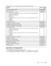
...161 Parts list-Overall No. CRU ID 1 LCD unit (see "LCD FRUs forThinkPad W700" on page 184, "LCD FRUs for ThinkPad W700ds" on page 188, "LCD FRUs for ThinkPad W701" on page 189, or "LCD FRUs for MXM NB9E-GLM3 42W8204 N • 2752-CTO, 36x, 37x, 38x, 3Ax,... and W700ds 45N6060 N 5 VGA thermal device and fan for W701 and W701ds 60Y4947 N 5 VGA thermal device and fan for W701 and W701ds 60Y4949 N 6 Structure frame for W700 and W700ds 45N6098 N 6 Structure frame for W701 and W701ds 60Y4940 N 7 Thermal putty for W701 and W701ds 75Y5867 N 8 Video card for MXM NB9E-GLM2 • ...
...161 Parts list-Overall No. CRU ID 1 LCD unit (see "LCD FRUs forThinkPad W700" on page 184, "LCD FRUs for ThinkPad W700ds" on page 188, "LCD FRUs for ThinkPad W701" on page 189, or "LCD FRUs for MXM NB9E-GLM3 42W8204 N • 2752-CTO, 36x, 37x, 38x, 3Ax,... and W700ds 45N6060 N 5 VGA thermal device and fan for W701 and W701ds 60Y4947 N 5 VGA thermal device and fan for W701 and W701ds 60Y4949 N 6 Structure frame for W700 and W700ds 45N6098 N 6 Structure frame for W701 and W701ds 60Y4940 N 7 Thermal putty for W701 and W701ds 75Y5867 N 8 Video card for MXM NB9E-GLM2 • ...
Hardware Maintenance Manual
Page 195
Table 62. FRU 1 LCD cover kit for ThinkPad W701 In ThinkPad W701, there are following types of LCDs. • 17.0-in . WXGAx, TFT LCD (Table 63 "Parts list-17.0-in . WUXGA TFT LCD (Table 64 "Parts list-...
Table 62. FRU 1 LCD cover kit for ThinkPad W701 In ThinkPad W701, there are following types of LCDs. • 17.0-in . WXGAx, TFT LCD (Table 63 "Parts list-17.0-in . WUXGA TFT LCD (Table 64 "Parts list-...


