Hardware Maintenance Manual
Page 4
General guidelines 65 Before servicing ThinkPad T530, T530i, and W530 66 1010 Battery pack 66 1020 Serial Ultrabay Enhanced device or blank bezel 67 1030 Memory module slot cover 68 1040 Memory module (bottom slot 69 1050 Hard disk drive or solid state drive. . . . . 70 1060 Keyboard 72 1070 Memory module (upper slot 75 1080 PCI Express Mini Card...
General guidelines 65 Before servicing ThinkPad T530, T530i, and W530 66 1010 Battery pack 66 1020 Serial Ultrabay Enhanced device or blank bezel 67 1030 Memory module slot cover 68 1040 Memory module (bottom slot 69 1050 Hard disk drive or solid state drive. . . . . 70 1060 Keyboard 72 1070 Memory module (upper slot 75 1080 PCI Express Mini Card...
Hardware Maintenance Manual
Page 60
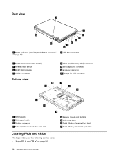
... 10 9 1 Status indicators (see Chapter 6 "Status indicators" on page 47) 2 3 4 5 6 7 8 6 USB 3.0 connectors 2 Smart card slot (on some models) 3 Wireless radio switch 4 IEEE 1394 connector 5 USB 2.0 connector Bottom view 8 7 7 Video graphics array (VGA) connector 8 Mini ... Always On USB connector 1 2 3 6 5 1 Battery pack 2 Battery pack latch 3 Docking connector 4 Solid state drive or hard disk drive slot 4 5 Memory module slot (bottom) 6 LCD cover latch 7 Serial Ultrabay Enhanced lock latch 8 Serial Ultrabay Enhanced eject latch Locating FRUs and CRUs This topic introduces the following...
... 10 9 1 Status indicators (see Chapter 6 "Status indicators" on page 47) 2 3 4 5 6 7 8 6 USB 3.0 connectors 2 Smart card slot (on some models) 3 Wireless radio switch 4 IEEE 1394 connector 5 USB 2.0 connector Bottom view 8 7 7 Video graphics array (VGA) connector 8 Mini ... Always On USB connector 1 2 3 6 5 1 Battery pack 2 Battery pack latch 3 Docking connector 4 Solid state drive or hard disk drive slot 4 5 Memory module slot (bottom) 6 LCD cover latch 7 Serial Ultrabay Enhanced lock latch 8 Serial Ultrabay Enhanced eject latch Locating FRUs and CRUs This topic introduces the following...
Hardware Maintenance Manual
Page 63
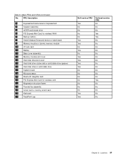
... Express Mini Card for wireless WAN 7 Backup battery 8 Serial Ultrabay Enhanced device or blank bezel 9 Memory module or dummy memory module 10 I/O sub card 11 Battery 12 Base cover assembly 13 Memory module slot cover 14 Hard disk drive slot cover 15 Hard disk drive rubber rails or solid state drive spacers 16 Hard disk...
... Express Mini Card for wireless WAN 7 Backup battery 8 Serial Ultrabay Enhanced device or blank bezel 9 Memory module or dummy memory module 10 I/O sub card 11 Battery 12 Base cover assembly 13 Memory module slot cover 14 Hard disk drive slot cover 15 Hard disk drive rubber rails or solid state drive spacers 16 Hard disk...
Hardware Maintenance Manual
Page 74
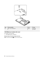
Step NA Screw (quantity) M3 × 5 mm, flat-head (1) 1030 Memory module slot cover For access, remove this FRU: • "1010 Battery pack" on page 66 Removal steps of memory module slot cover Note: Loosen the screws 1 , but do not remove them. Color Black Torque 0.392 Nm (4 kgfcm) 68 Hardware Maintenance Manual
Step NA Screw (quantity) M3 × 5 mm, flat-head (1) 1030 Memory module slot cover For access, remove this FRU: • "1010 Battery pack" on page 66 Removal steps of memory module slot cover Note: Loosen the screws 1 , but do not remove them. Color Black Torque 0.392 Nm (4 kgfcm) 68 Hardware Maintenance Manual
Hardware Maintenance Manual
Page 75
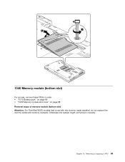
Removing or replacing a FRU 69 Otherwise, the system might not function correctly. Chapter 10. 1 2 1040 Memory module (bottom slot) For access, remove these FRUs in order: • "1010 Battery pack" on page 66 • "1030 Memory module slot cover" on page 68 Removal steps of memory module (bottom slot) Attention: For ThinkPad W530 models that come with two dummy cards installed, do not replace the dummy cards with memory modules.
Removing or replacing a FRU 69 Otherwise, the system might not function correctly. Chapter 10. 1 2 1040 Memory module (bottom slot) For access, remove these FRUs in order: • "1010 Battery pack" on page 66 • "1030 Memory module slot cover" on page 68 Removal steps of memory module (bottom slot) Attention: For ThinkPad W530 models that come with two dummy cards installed, do not replace the dummy cards with memory modules.

Hardware Maintenance Manual
Page 76
...; Do not drop the drive or apply any physical shock to physical shock. 1 2 1 When installing: Insert the notched end of the memory module into place. The drive is in the slot and does not move easily. 1050 Hard disk drive or solid state drive For access, remove this FRU: • "1010 Battery... pack" on it if possible. • Never remove the drive while the system is operating or is sensitive to it snaps into the slot. Removal steps of hard disk drive or solid state drive Note: Loosen the screw 1 , but do not remove it is firmly installed in suspend mode...
...; Do not drop the drive or apply any physical shock to physical shock. 1 2 1 When installing: Insert the notched end of the memory module into place. The drive is in the slot and does not move easily. 1050 Hard disk drive or solid state drive For access, remove this FRU: • "1010 Battery... pack" on it if possible. • Never remove the drive while the system is operating or is sensitive to it snaps into the slot. Removal steps of hard disk drive or solid state drive Note: Loosen the screw 1 , but do not remove it is firmly installed in suspend mode...
Hardware Maintenance Manual
Page 78
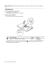
... edge of the keyboard is attached firmly. 1060 Keyboard For access, remove these FRUs in order: • "1010 Battery pack" on page 66 • "1030 Memory module slot cover" on page 68 Removal steps of keyboard 1. When installing: Make sure that secure the keyboard. 1 1 Step 1 Screw (quantity) M2 × 14 mm, wafer...
... edge of the keyboard is attached firmly. 1060 Keyboard For access, remove these FRUs in order: • "1010 Battery pack" on page 66 • "1030 Memory module slot cover" on page 68 Removal steps of keyboard 1. When installing: Make sure that secure the keyboard. 1 1 Step 1 Screw (quantity) M2 × 14 mm, wafer...
Hardware Maintenance Manual
Page 81
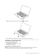
... access, remove these FRUs in order: • "1010 Battery pack" on page 66 • "1030 Memory module slot cover" on page 68 • "1060 Keyboard" on page 72 Removal steps of memory module (upper slot) Attention: For ThinkPad W530 models that the front side of the keyboard b is housed firmly. b b 4. Otherwise, the system might not function...
... access, remove these FRUs in order: • "1010 Battery pack" on page 66 • "1030 Memory module slot cover" on page 68 • "1060 Keyboard" on page 72 Removal steps of memory module (upper slot) Attention: For ThinkPad W530 models that the front side of the keyboard b is housed firmly. b b 4. Otherwise, the system might not function...
Hardware Maintenance Manual
Page 82
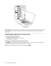
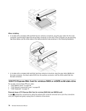
...direction of the arrow. When installing: Insert the notched end of the memory module into place. Make sure that it snaps into the socket. Press the memory module firmly, and pivot it until it is firmly installed in the slot and does not move easily. 1080 PCI Express Mini Card for wireless LAN... For access, remove these FRUs in order: • "1010 Battery pack" on page 66 • "1030 Memory module slot cover" on page 68 • "1060 Keyboard" on page 72 Removal steps of PCI Express Mini Card for wireless LAN In step 1 , unplug the connectors...
...direction of the arrow. When installing: Insert the notched end of the memory module into place. Make sure that it snaps into the socket. Press the memory module firmly, and pivot it until it is firmly installed in the slot and does not move easily. 1080 PCI Express Mini Card for wireless LAN... For access, remove these FRUs in order: • "1010 Battery pack" on page 66 • "1030 Memory module slot cover" on page 68 • "1060 Keyboard" on page 72 Removal steps of PCI Express Mini Card for wireless LAN In step 1 , unplug the connectors...
Hardware Maintenance Manual
Page 84
... in the following illustration. • In models with your fingers and gently unplug them in order: • "1010 Battery pack" on page 66 • "1030 Memory module slot cover" on page 68 • "1060 Keyboard" on page 72 Removal steps of the arrow. 78 Hardware Maintenance Manual
... in the following illustration. • In models with your fingers and gently unplug them in order: • "1010 Battery pack" on page 66 • "1030 Memory module slot cover" on page 68 • "1060 Keyboard" on page 72 Removal steps of the arrow. 78 Hardware Maintenance Manual
Hardware Maintenance Manual
Page 89
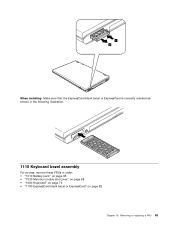
Removing or replacing a FRU 83 1 2 When installing: Make sure that the ExpressCard blank bezel or ExpressCard is correctly oriented as shown in the following illustration. 1110 Keyboard bezel assembly For access, remove these FRUs in order: • "1010 Battery pack" on page 66 • "1030 Memory module slot cover" on page 68 • "1060 Keyboard" on page 72 • "1100 ExpressCard blank bezel or ExpressCard" on page 82 Chapter 10.
Removing or replacing a FRU 83 1 2 When installing: Make sure that the ExpressCard blank bezel or ExpressCard is correctly oriented as shown in the following illustration. 1110 Keyboard bezel assembly For access, remove these FRUs in order: • "1010 Battery pack" on page 66 • "1030 Memory module slot cover" on page 68 • "1060 Keyboard" on page 72 • "1100 ExpressCard blank bezel or ExpressCard" on page 82 Chapter 10.
Hardware Maintenance Manual
Page 92
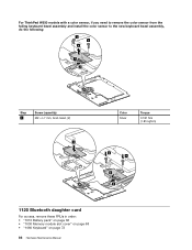
For ThinkPad W530 models with a color sensor, if you need to remove the color sensor from the failing keyboard bezel assembly and install the color sensor to the new keyboard bezel assembly, do the following: 3 3 4 1 2 Step 3 Screw (quantity) M2 × L7 mm, bind-head, (2) 1 Color Silver Torque 0.181 Nm (1.85 kgfcm) 4 4 3 2 1120 Bluetooth daughter card For access, remove these FRUs in order: • "1010 Battery pack" on page 66 • "1030 Memory module slot cover" on page 68 • "1060 Keyboard" on page 72 86 Hardware Maintenance Manual
For ThinkPad W530 models with a color sensor, if you need to remove the color sensor from the failing keyboard bezel assembly and install the color sensor to the new keyboard bezel assembly, do the following: 3 3 4 1 2 Step 3 Screw (quantity) M2 × L7 mm, bind-head, (2) 1 Color Silver Torque 0.181 Nm (1.85 kgfcm) 4 4 3 2 1120 Bluetooth daughter card For access, remove these FRUs in order: • "1010 Battery pack" on page 66 • "1030 Memory module slot cover" on page 68 • "1060 Keyboard" on page 72 86 Hardware Maintenance Manual
Hardware Maintenance Manual
Page 93
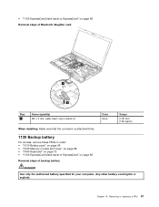
... the connector is attached firmly. 1130 Backup battery For access, remove these FRUs in order: • "1010 Battery pack" on page 66 • "1030 Memory module slot cover" on page 68 • "1060 Keyboard" on page 72 • "1100 ExpressCard blank bezel or ExpressCard" on page 82 Removal steps of backup battery...
... the connector is attached firmly. 1130 Backup battery For access, remove these FRUs in order: • "1010 Battery pack" on page 66 • "1030 Memory module slot cover" on page 68 • "1060 Keyboard" on page 72 • "1100 ExpressCard blank bezel or ExpressCard" on page 82 Removal steps of backup battery...
Hardware Maintenance Manual
Page 94
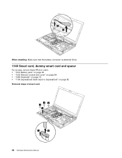
When installing: Make sure that the battery connector is attached firmly. 1140 Smart card, dummy smart card and spacer For access, remove these FRUs in order: • "1010 Battery pack" on page 66 • "1030 Memory module slot cover" on page 68 • "1060 Keyboard" on page 72 • "1100 ExpressCard blank bezel or ExpressCard" on page 82 Removal steps of smart card 33 3 4 1 2 88 Hardware Maintenance Manual
When installing: Make sure that the battery connector is attached firmly. 1140 Smart card, dummy smart card and spacer For access, remove these FRUs in order: • "1010 Battery pack" on page 66 • "1030 Memory module slot cover" on page 68 • "1060 Keyboard" on page 72 • "1100 ExpressCard blank bezel or ExpressCard" on page 82 Removal steps of smart card 33 3 4 1 2 88 Hardware Maintenance Manual
Hardware Maintenance Manual
Page 95
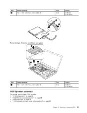
Removing or replacing a FRU 89 Step 3 Screw (quantity) M2 × 3 mm, wafer-head, nylon-coated (3) Color Silver Torque 0.181 Nm (1.85 kgfcm) 5 6 5 Removal steps of dummy smart card and spacer 3 1 1 1 2 Step 1 Screw (quantity) M2 × 3 mm, wafer-head, nylon-coated (3) Color Silver 1150 Speaker assembly For access, remove these FRUs in order: • "1010 Battery pack" on page 66 • "1030 Memory module slot cover" on page 68 • "1060 Keyboard" on page 72 • "1100 ExpressCard blank bezel or ExpressCard" on page 82 Torque 0.181 Nm (1.85 kgfcm) Chapter 10.
Removing or replacing a FRU 89 Step 3 Screw (quantity) M2 × 3 mm, wafer-head, nylon-coated (3) Color Silver Torque 0.181 Nm (1.85 kgfcm) 5 6 5 Removal steps of dummy smart card and spacer 3 1 1 1 2 Step 1 Screw (quantity) M2 × 3 mm, wafer-head, nylon-coated (3) Color Silver 1150 Speaker assembly For access, remove these FRUs in order: • "1010 Battery pack" on page 66 • "1030 Memory module slot cover" on page 68 • "1060 Keyboard" on page 72 • "1100 ExpressCard blank bezel or ExpressCard" on page 82 Torque 0.181 Nm (1.85 kgfcm) Chapter 10.
(English) User Guide
Page 94
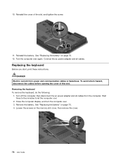
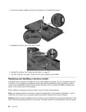
... battery. See "Replacing the battery" on the memory slot cover, then remove the cover. 76 User Guide Connect the ac power adapter and all cables from power and communication cables is hazardous. To avoid shock hazard, disconnect the cables before opening the cover of the slot, and tighten the screw. 11. Remove the... the following: 1. Wait three to five minutes to let the computer cool. 2. See "Replacing the battery" on page 70. 4. 10. Reinstall the cover of this slot. Turn the computer over . 3. DANGER Electric current from the computer.
... battery. See "Replacing the battery" on the memory slot cover, then remove the cover. 76 User Guide Connect the ac power adapter and all cables from power and communication cables is hazardous. To avoid shock hazard, disconnect the cables before opening the cover of the slot, and tighten the screw. 11. Remove the... the following: 1. Wait three to five minutes to let the computer cool. 2. See "Replacing the battery" on page 70. 4. 10. Reinstall the cover of this slot. Turn the computer over . 3. DANGER Electric current from the computer.
(English) User Guide
Page 98
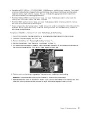
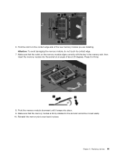
Reinstall the memory slot cover back in the memory slot of the computer. Connect the ac power adapter and all cables. Reinstall the screws. 5. Replacing and installing a memory module Increasing memory capacity is an effective way to follow the precautions. In some conditions, the memory in your body.... See "Replacing the battery" on the system configuration. The static electricity could damage the memory module. 80 User Guide Reinstall the battery. You can increase the amount of the memory module has dependency on page 70. 7. Close the computer display, and turn the computer...
Reinstall the memory slot cover back in the memory slot of the computer. Connect the ac power adapter and all cables. Reinstall the screws. 5. Replacing and installing a memory module Increasing memory capacity is an effective way to follow the precautions. In some conditions, the memory in your body.... See "Replacing the battery" on the system configuration. The static electricity could damage the memory module. 80 User Guide Reinstall the battery. You can increase the amount of the memory module has dependency on page 70. 7. Close the computer display, and turn the computer...
(English) User Guide
Page 99
... at the bottom side of the computer. • If your Lenovo reseller or a marketing representative. • ThinkPad T530 and T530i have two memory slots, one under the keyboard and the other under the memory slot cover at the bottom side of the computer. • ThinkPad W530 has four memory slots, two under the keyboard and the other two under the...
... at the bottom side of the computer. • If your Lenovo reseller or a marketing representative. • ThinkPad T530 and T530i have two memory slots, one under the keyboard and the other under the memory slot cover at the bottom side of the computer. • ThinkPad W530 has four memory slots, two under the keyboard and the other two under the...
(English) User Guide
Page 100
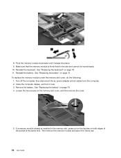
... computer. 2. See "Replacing the battery" on the memory slot cover, and then remove the cover. 5. Loosen the two screws on page 70. 4. 8. See "Replacing the keyboard" on page 70. To replace the memory module under the memory slot cover, do the following: 1. Remove the battery. Reinstall... the keyboard. If a memory module already is firmly fixed in the memory slot, press out on the latches on both edges of the socket at...
... computer. 2. See "Replacing the battery" on the memory slot cover, and then remove the cover. 5. Loosen the two screws on page 70. 4. 8. See "Replacing the keyboard" on page 70. To replace the memory module under the memory slot cover, do the following: 1. Remove the battery. Reinstall... the keyboard. If a memory module already is firmly fixed in the memory slot, press out on the latches on both edges of the socket at...
(English) User Guide
Page 101
... aligns correctly with the key in the slot and cannot be moved easily. 10. Chapter 6. 6. Attention: To avoid damaging the memory module, do not touch its contact edge. 7. Make sure that the memory module is firmly installed in the memory slot, then insert the memory module into place. 9. Pivot the memory module downward until it in place.
... aligns correctly with the key in the slot and cannot be moved easily. 10. Chapter 6. 6. Attention: To avoid damaging the memory module, do not touch its contact edge. 7. Make sure that the memory module is firmly installed in the memory slot, then insert the memory module into place. 9. Pivot the memory module downward until it in place.


