Hardware Maintenance Manual
Page 40
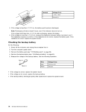
... the resistance between battery terminals 5 and 7. Checking the backup battery Do the following illustration. Remove the backup battery (see "1010 Battery pack" on . Wire Red Black Voltage (V dc) +2.5 to +3.2 Ground • If the voltage is correct, replace the system board. • If the voltage is not correct, replace the battery pack...
... the resistance between battery terminals 5 and 7. Checking the backup battery Do the following illustration. Remove the backup battery (see "1010 Battery pack" on . Wire Red Black Voltage (V dc) +2.5 to +3.2 Ground • If the voltage is correct, replace the system board. • If the voltage is not correct, replace the battery pack...
Hardware Maintenance Manual
Page 59
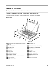
... Color sensor (on some models) 15 Touch pad buttons 16 Touch pad 17 TrackPoint buttons 18 TrackPoint pointing stick 19 UltraNav® pointing device 20 Black button 21 Volume control buttons © Copyright Lenovo 2012 53
... Color sensor (on some models) 15 Touch pad buttons 16 Touch pad 17 TrackPoint buttons 18 TrackPoint pointing stick 19 UltraNav® pointing device 20 Black button 21 Volume control buttons © Copyright Lenovo 2012 53
Hardware Maintenance Manual
Page 74
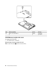
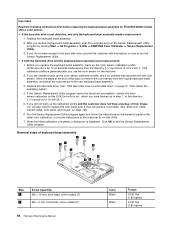
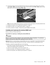
Step NA Screw (quantity) M3 × 5 mm, flat-head (1) 1030 Memory module slot cover For access, remove this FRU: • "1010 Battery pack" on page 66 Removal steps of memory module slot cover Note: Loosen the screws 1 , but do not remove them. Color Black Torque 0.392 Nm (4 kgfcm) 68 Hardware Maintenance Manual
Step NA Screw (quantity) M3 × 5 mm, flat-head (1) 1030 Memory module slot cover For access, remove this FRU: • "1010 Battery pack" on page 66 Removal steps of memory module slot cover Note: Loosen the screws 1 , but do not remove them. Color Black Torque 0.392 Nm (4 kgfcm) 68 Hardware Maintenance Manual
Hardware Maintenance Manual
Page 78
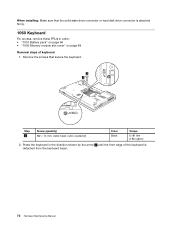
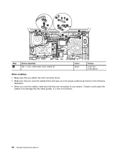
When installing: Make sure that secure the keyboard. 1 1 Step 1 Screw (quantity) M2 × 14 mm, wafer-head, nylon-coated (2) Color Black Torque 0.181 Nm (1.85 kgfcm) 2. Remove the screws that the solid state drive connector or hard disk drive connector is detached from the keyboard bezel. ...
When installing: Make sure that secure the keyboard. 1 1 Step 1 Screw (quantity) M2 × 14 mm, wafer-head, nylon-coated (2) Color Black Torque 0.181 Nm (1.85 kgfcm) 2. Remove the screws that the solid state drive connector or hard disk drive connector is detached from the keyboard bezel. ...
Hardware Maintenance Manual
Page 84
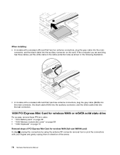
... following illustration. • In models with a wireless LAN card that has two antenna connectors, plug the gray cable into the main connector, and the black cable into the last connector, 1090 PCI Express Mini Card for wireless WAN (full-size WWAN card) In step 1 , unplug the connectors by using ...tool or pick the connectors with a wireless LAN card that has three antenna connectors, plug the gray cable (MAIN) into the main connector, the black cable (AUX) into the auxiliary connector, and the white cable (3rd) into the auxiliary connector on page 72 Removal steps of PCI Express Mini ...
... following illustration. • In models with a wireless LAN card that has two antenna connectors, plug the gray cable into the main connector, and the black cable into the last connector, 1090 PCI Express Mini Card for wireless WAN (full-size WWAN card) In step 1 , unplug the connectors by using ...tool or pick the connectors with a wireless LAN card that has three antenna connectors, plug the gray cable (MAIN) into the main connector, the black cable (AUX) into the auxiliary connector, and the white cable (3rd) into the auxiliary connector on page 72 Removal steps of PCI Express Mini ...
Hardware Maintenance Manual
Page 90
... (quantity) M2 × 14 mm, bind-head, nylon-coated (7) M2 × 4 mm, bind-head, nylon-coated (2) 84 Hardware Maintenance Manual Color Black Black Torque 0.181 Nm (1.85 kgfcm) 0.181 Nm (1.85 kgfcm) When the initial calibration completes, a dialog box is generated after you replace the keyboard bezel assembly... PANTONE Color Calibrator ➙ Sensor Replacement Utility. 3. This calibration profile is displayed. After you use the color sensor for ThinkPad W530 models with information on how to replace the LCD panel even if the LCD panel is not defective, and only the keyboard...
... (quantity) M2 × 14 mm, bind-head, nylon-coated (7) M2 × 4 mm, bind-head, nylon-coated (2) 84 Hardware Maintenance Manual Color Black Black Torque 0.181 Nm (1.85 kgfcm) 0.181 Nm (1.85 kgfcm) When the initial calibration completes, a dialog box is generated after you replace the keyboard bezel assembly... PANTONE Color Calibrator ➙ Sensor Replacement Utility. 3. This calibration profile is displayed. After you use the color sensor for ThinkPad W530 models with information on how to replace the LCD panel even if the LCD panel is not defective, and only the keyboard...
Hardware Maintenance Manual
Page 101
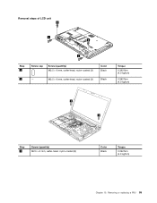
M2.5 × 6 mm, wafer-head, nylon-coated (2) Color Black Black Torque 0.392 Nm (4.0 kgfcm) 0.392 Nm (4.0 kgfcm) 3 3 Step 3 Screw (quantity) M2.5 × 6 mm, wafer-head, nylon-coated (2) Color Black Torque 0.392 Nm (4.0 kgfcm) Chapter 10. Removal steps of LCD unit 2 1 2 1 Step 1 Screw cap Screw (quantity) M2.5 × 6 mm, wafer-head, nylon-coated (2) 2 - Removing or replacing a FRU 95
M2.5 × 6 mm, wafer-head, nylon-coated (2) Color Black Black Torque 0.392 Nm (4.0 kgfcm) 0.392 Nm (4.0 kgfcm) 3 3 Step 3 Screw (quantity) M2.5 × 6 mm, wafer-head, nylon-coated (2) Color Black Torque 0.392 Nm (4.0 kgfcm) Chapter 10. Removal steps of LCD unit 2 1 2 1 Step 1 Screw cap Screw (quantity) M2.5 × 6 mm, wafer-head, nylon-coated (2) 2 - Removing or replacing a FRU 95
Hardware Maintenance Manual
Page 102
4 4 7 5 6 99 8 9 9 8 8 9 9 8 Step 4 Screw (quantity) M2 × 4 mm, wafer-head, nylon-coated (2) Color Black Torque 0.181 Nm (1.85 kgfcm) When installing: • Make sure that you attach the LCD connector firmly. • Make sure that you route the cables firmly and tape up in the proper positions as shown in the following illustration. • When you route the cables, make sure that they are not subject to be broken. 96 Hardware Maintenance Manual Tension could cause the cables to be damaged by the cable guides, or a wire to any tension.
4 4 7 5 6 99 8 9 9 8 8 9 9 8 Step 4 Screw (quantity) M2 × 4 mm, wafer-head, nylon-coated (2) Color Black Torque 0.181 Nm (1.85 kgfcm) When installing: • Make sure that you attach the LCD connector firmly. • Make sure that you route the cables firmly and tape up in the proper positions as shown in the following illustration. • When you route the cables, make sure that they are not subject to be broken. 96 Hardware Maintenance Manual Tension could cause the cables to be damaged by the cable guides, or a wire to any tension.
Hardware Maintenance Manual
Page 104
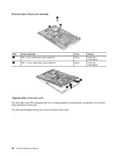
Removal steps of base cover assembly 1 1 2 Step 1 2 Screw (quantity) M2 × 3 mm, wafer-head, nylon-coated (2) M2 × 14 mm, wafer-head, nylon-coated (1) Color Silver Black Torque 0.181 Nm (1.85 kgfcm) 0.181 Nm (1.85 kgfcm) 4 3 Applying labels to those described in this topic. The following illustration shows the correct location of several kinds, including but not limited to the base cover The new base cover FRU is shipped with a kit containing labels of each label. 98 Hardware Maintenance Manual
Removal steps of base cover assembly 1 1 2 Step 1 2 Screw (quantity) M2 × 3 mm, wafer-head, nylon-coated (2) M2 × 14 mm, wafer-head, nylon-coated (1) Color Silver Black Torque 0.181 Nm (1.85 kgfcm) 0.181 Nm (1.85 kgfcm) 4 3 Applying labels to those described in this topic. The following illustration shows the correct location of several kinds, including but not limited to the base cover The new base cover FRU is shipped with a kit containing labels of each label. 98 Hardware Maintenance Manual
Hardware Maintenance Manual
Page 110
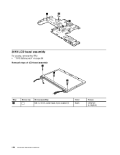
a b c d 2010 LCD bezel assembly For access, remove this FRU: • "1010 Battery pack" on page 66 Removal steps of LCD bezel assembly 1 1 1 Step 1 Screw cap Screw (quantity) M2.5 × 6 mm, wafer-head, nylon-coated (3) Color Black Torque 0.392 Nm (4.0 kgfcm) 104 Hardware Maintenance Manual
a b c d 2010 LCD bezel assembly For access, remove this FRU: • "1010 Battery pack" on page 66 Removal steps of LCD bezel assembly 1 1 1 Step 1 Screw cap Screw (quantity) M2.5 × 6 mm, wafer-head, nylon-coated (3) Color Black Torque 0.392 Nm (4.0 kgfcm) 104 Hardware Maintenance Manual
Hardware Maintenance Manual
Page 114
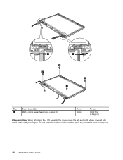
Do not press the surface of the panel or apply any excessive force to the cover, press the left and right edges covered with metal gently with your fingers. 1 1 2 2 2 2 Step 2 Screw (quantity) M2.5 × 6 mm, wafer-head, nylon-coated (4) Color Black Torque 0.392 Nm (4.0 kgfcm) When installing: When attaching the LCD panel to the panel. 108 Hardware Maintenance Manual
Do not press the surface of the panel or apply any excessive force to the cover, press the left and right edges covered with metal gently with your fingers. 1 1 2 2 2 2 Step 2 Screw (quantity) M2.5 × 6 mm, wafer-head, nylon-coated (4) Color Black Torque 0.392 Nm (4.0 kgfcm) When installing: When attaching the LCD panel to the panel. 108 Hardware Maintenance Manual

Hardware Maintenance Manual
Page 117
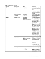
Removing or replacing a FRU 111 b Wireless LAN antenna, AUX (black) c Wireless LAN antenna, 3rd (white) d Wireless LAN antenna, MAIN (gray) e Wireless WAN antenna, MAIN (red) a b c d e Chapter 10.
Removing or replacing a FRU 111 b Wireless LAN antenna, AUX (black) c Wireless LAN antenna, 3rd (white) d Wireless LAN antenna, MAIN (gray) e Wireless WAN antenna, MAIN (red) a b c d e Chapter 10.
(English) User Guide
Page 20
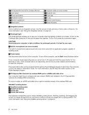
...integrated camera. UltraNav® pointing device 6 TrackPoint pointing stick 13 TrackPoint buttons 12 Touch pad 11 Touch pad buttons The keyboard contains the Lenovo unique UltraNav pointing device. To turn off , press the combination again. To turn it off, press and hold a video conference. ... PCI Express Mini Card slot for wireless LAN card 9 Color sensor 11 Touch pad buttons 13 TrackPoint buttons 15 Memory-upgrade slot 17 Black button 8 Fingerprint reader (on some models) The built-in microphones capture sound and voice when used with an application program capable of ...
...integrated camera. UltraNav® pointing device 6 TrackPoint pointing stick 13 TrackPoint buttons 12 Touch pad 11 Touch pad buttons The keyboard contains the Lenovo unique UltraNav pointing device. To turn off , press the combination again. To turn it off, press and hold a video conference. ... PCI Express Mini Card slot for wireless LAN card 9 Color sensor 11 Touch pad buttons 13 TrackPoint buttons 15 Memory-upgrade slot 17 Black button 8 Fingerprint reader (on some models) The built-in microphones capture sound and voice when used with an application program capable of ...
(English) User Guide
Page 21
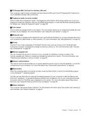
... of your fingerprint to measure and adjust the color accuracy of your displays. You also can increase the amount of ThinkPad® function keys, such as options from Lenovo. For more information, see "Using the fingerprint reader" on some models) Some models have a fingerprint reader. Memory... the sound volume, mute the speakers, or mute the microphones of each indicator, see "Volume and mute buttons" on page 24. 17 Black button When the operating system is equipped with a color sensor. For more information, see "Function key combinations" on page 23. 15 Memory...
... of your fingerprint to measure and adjust the color accuracy of your displays. You also can increase the amount of ThinkPad® function keys, such as options from Lenovo. For more information, see "Using the fingerprint reader" on some models) Some models have a fingerprint reader. Memory... the sound volume, mute the speakers, or mute the microphones of each indicator, see "Volume and mute buttons" on page 24. 17 Black button When the operating system is equipped with a color sensor. For more information, see "Function key combinations" on page 23. 15 Memory...
(English) User Guide
Page 31
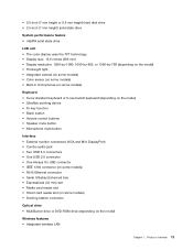
... (on some models) Keyboard • 6-row standard keyboard or 6-row backlit keyboard (depending on the model) • UltraNav pointing device • Fn key function • Black button • Volume control buttons • Speaker mute button • Microphone mute button Interface • External monitor connectors (VGA and Mini DisplayPort) • Combo audio...
... (on some models) Keyboard • 6-row standard keyboard or 6-row backlit keyboard (depending on the model) • UltraNav pointing device • Fn key function • Black button • Volume control buttons • Speaker mute button • Microphone mute button Interface • External monitor connectors (VGA and Mini DisplayPort) • Combo audio...
(English) User Guide
Page 37
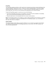
... to the volume control buttons). System Update The System Update program helps you have launched the SimpleTap program for the first time. • Press the black button on certain models preinstalled with a quick way to -date by downloading and installing software packages (ThinkVantage applications, device drivers, UEFI BIOS updates, and other... computer operating system, launching a program, opening a Web page, opening a file, and so on the desktop. You also can use the SimpleTap program to access the Lenovo App Shop, from http://www...
... to the volume control buttons). System Update The System Update program helps you have launched the SimpleTap program for the first time. • Press the black button on certain models preinstalled with a quick way to -date by downloading and installing software packages (ThinkVantage applications, device drivers, UEFI BIOS updates, and other... computer operating system, launching a program, opening a Web page, opening a file, and so on the desktop. You also can use the SimpleTap program to access the Lenovo App Shop, from http://www...
(English) User Guide
Page 59
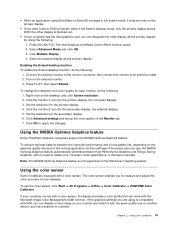
... or intervene manually. Set the resolution for the primary display, the computer display). 3. Using your displays. • When an application using is blacked out. • If your computer comes with a color sensor, the display provides a color profile that can work with a color sensor. Press...settings and set up the color quality on the desktop, and click Screen resolution. 2. Using the NVIDIA Optimus Graphics feature Some ThinkPad notebook computers support the NVIDIA Optimus Graphics feature. Using the color sensor Some models are using DirectDraw or Direct3D is played in ...
... or intervene manually. Set the resolution for the primary display, the computer display). 3. Using your displays. • When an application using is blacked out. • If your computer comes with a color sensor, the display provides a color profile that can work with a color sensor. Press...settings and set up the color quality on the desktop, and click Screen resolution. 2. Using the NVIDIA Optimus Graphics feature Some ThinkPad notebook computers support the NVIDIA Optimus Graphics feature. Using the color sensor Some models are using DirectDraw or Direct3D is played in ...
(English) User Guide
Page 83
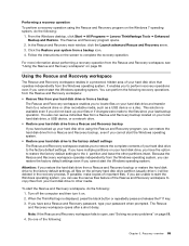
...partitions on the screen to complete the recovery operation. This solution is displayed, press the black button or repeatedly press and release the F11 key. 3. If you are unable to ... workspace" on page 68. 4. From the Windows desktop, click Start ➙ All Programs ➙ Lenovo ThinkVantage Tools ➙ Enhanced Backup and Restore. For more information about performing a recovery operation from the Rescue... if you did not back up your last backup operation. When the ThinkPad logo is available even if you cannot start the Windows operating system. If you cannot ...
...partitions on the screen to complete the recovery operation. This solution is displayed, press the black button or repeatedly press and release the F11 key. 3. If you are unable to ... workspace" on page 68. 4. From the Windows desktop, click Start ➙ All Programs ➙ Lenovo ThinkVantage Tools ➙ Enhanced Backup and Restore. For more information about performing a recovery operation from the Rescue... if you did not back up your last backup operation. When the ThinkPad logo is available even if you cannot start the Windows operating system. If you cannot ...
(English) User Guide
Page 105
... gray cable to the connector marked TR1 or Main on the card, the white cable to the connector marked RO or TR3 (center), and the black cable to the connector marked TR2 or Aux. Reinstall the battery.
... gray cable to the connector marked TR1 or Main on the card, the white cable to the connector marked RO or TR3 (center), and the black cable to the connector marked TR2 or Aux. Reinstall the battery.
(English) User Guide
Page 137
To display the Startup Interrupt Menu window, press the black button or Enter key during the power-on self-test (POST). If you select Permanently Disabled, you select Enabled, Intel AMT (Active Management Technology) is ...
To display the Startup Interrupt Menu window, press the black button or Enter key during the power-on self-test (POST). If you select Permanently Disabled, you select Enabled, Intel AMT (Active Management Technology) is ...
