Hardware Maintenance Manual
Page 45
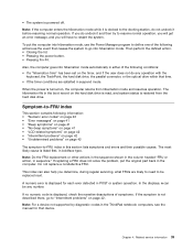
...listed first, in either of symptoms. If the symptom is turned on page 42. Do not replace a nondefective FRU. In the displays, n can also help you will have to be any operation with the keyboard, the TrackPoint, the hard disk drive, the parallel connector, or the optical drive within that device... it is docked to go to -FRU index in POST or system operation. Note: For a device not supported by diagnostic codes in the ThinkPad notebook computers, see the manual for each error detected in this section lists symptoms and errors and their possible causes. When the power is not...
...listed first, in either of symptoms. If the symptom is turned on page 42. Do not replace a nondefective FRU. In the displays, n can also help you will have to be any operation with the keyboard, the TrackPoint, the hard disk drive, the parallel connector, or the optical drive within that device... it is docked to go to -FRU index in POST or system operation. Note: For a device not supported by diagnostic codes in the ThinkPad notebook computers, see the manual for each error detected in this section lists symptoms and errors and their possible causes. When the power is not...
Hardware Maintenance Manual
Page 61
...: These CRUs are available from Lenovo at http://www.lenovo.com/support. ThinkPad computers contain the following types of CRUs include the ac power adapter, power cord, battery, and hard disk drive. If you . and (2) you might include the memory module, wireless card, keyboard, and palm rest with a replacement part you can find the manual...
...: These CRUs are available from Lenovo at http://www.lenovo.com/support. ThinkPad computers contain the following types of CRUs include the ac power adapter, power cord, battery, and hard disk drive. If you . and (2) you might include the memory module, wireless card, keyboard, and palm rest with a replacement part you can find the manual...
Hardware Maintenance Manual
Page 79
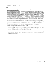
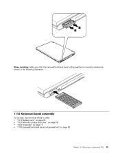
Chapter 10. Lift the keyboard in the direction shown by the arrow 3 , and then detach the connector 4 . 3 4 Installation steps of keyboard When installing the keyboard, do the following: 1. Removing or replacing a FRU 73 Attach the keyboard connector 1 . 3.
Chapter 10. Lift the keyboard in the direction shown by the arrow 3 , and then detach the connector 4 . 3 4 Installation steps of keyboard When installing the keyboard, do the following: 1. Removing or replacing a FRU 73 Attach the keyboard connector 1 . 3.
Hardware Maintenance Manual
Page 81
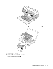
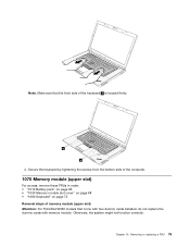
... page 66 • "1030 Memory module slot cover" on page 68 • "1060 Keyboard" on page 72 Removal steps of memory module (upper slot) Attention: For ThinkPad W530 models that the front side of the keyboard b is housed firmly. Removing or replacing a FRU 75 b b 4. Chapter 10. Otherwise, the system might not function correctly. Note: Make...
... page 66 • "1030 Memory module slot cover" on page 68 • "1060 Keyboard" on page 72 Removal steps of memory module (upper slot) Attention: For ThinkPad W530 models that the front side of the keyboard b is housed firmly. Removing or replacing a FRU 75 b b 4. Chapter 10. Otherwise, the system might not function correctly. Note: Make...
Hardware Maintenance Manual
Page 89
1 2 When installing: Make sure that the ExpressCard blank bezel or ExpressCard is correctly oriented as shown in the following illustration. 1110 Keyboard bezel assembly For access, remove these FRUs in order: • "1010 Battery pack" on page 66 • "1030 Memory module slot cover" on page 68 • "1060 Keyboard" on page 72 • "1100 ExpressCard blank bezel or ExpressCard" on page 82 Chapter 10. Removing or replacing a FRU 83
1 2 When installing: Make sure that the ExpressCard blank bezel or ExpressCard is correctly oriented as shown in the following illustration. 1110 Keyboard bezel assembly For access, remove these FRUs in order: • "1010 Battery pack" on page 66 • "1030 Memory module slot cover" on page 68 • "1060 Keyboard" on page 72 • "1100 ExpressCard blank bezel or ExpressCard" on page 82 Chapter 10. Removing or replacing a FRU 83
Hardware Maintenance Manual
Page 90
...color sensor for ThinkPad W530 models with information on the screen to perform the initial color calibration, or provide instructions to the customer to run the Sensor Replacement Utility program by clicking Start ➙ All Programs ➙ X-Rite ➙ PANTONE Color Calibrator ➙ Sensor Replacement Utility. 3. ...to the hard disk drive, provide the customer with a color sensor. • If the hard disk drive is not broken. Replace the keyboard bezel assembly. 2. If you are unable to back up the color sensor calibration profile, and if no problem was reported with ...
...color sensor for ThinkPad W530 models with information on the screen to perform the initial color calibration, or provide instructions to the customer to run the Sensor Replacement Utility program by clicking Start ➙ All Programs ➙ X-Rite ➙ PANTONE Color Calibrator ➙ Sensor Replacement Utility. 3. ...to the hard disk drive, provide the customer with a color sensor. • If the hard disk drive is not broken. Replace the keyboard bezel assembly. 2. If you are unable to back up the color sensor calibration profile, and if no problem was reported with ...
Hardware Maintenance Manual
Page 93
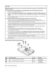
Any other battery could ignite or explode. Removing or replacing a FRU 87 • "1100 ExpressCard blank bezel or ExpressCard" on page 82 Removal steps of Bluetooth daughter card Step 1 Screw (quantity) M2 × 3 mm, wafer-... For access, remove these FRUs in order: • "1010 Battery pack" on page 66 • "1030 Memory module slot cover" on page 68 • "1060 Keyboard" on page 72 • "1100 ExpressCard blank bezel or ExpressCard" on page 82 Removal steps of backup battery DANGER Use only the authorized battery specified...
Any other battery could ignite or explode. Removing or replacing a FRU 87 • "1100 ExpressCard blank bezel or ExpressCard" on page 82 Removal steps of Bluetooth daughter card Step 1 Screw (quantity) M2 × 3 mm, wafer-... For access, remove these FRUs in order: • "1010 Battery pack" on page 66 • "1030 Memory module slot cover" on page 68 • "1060 Keyboard" on page 72 • "1100 ExpressCard blank bezel or ExpressCard" on page 82 Removal steps of backup battery DANGER Use only the authorized battery specified...
Hardware Maintenance Manual
Page 95
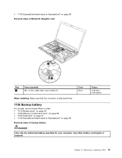
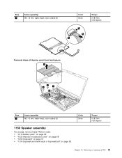
Removing or replacing a FRU 89 Step 3 Screw (quantity) M2 × 3 mm, wafer-head, nylon-coated (3) Color Silver Torque 0.181 Nm (1.85 kgfcm) 5 6 5 Removal steps of dummy smart card and spacer 3 1 1 1 2 Step 1 Screw (quantity) M2 × 3 mm, wafer-head, nylon-coated (3) Color Silver 1150 Speaker assembly For access, remove these FRUs in order: • "1010 Battery pack" on page 66 • "1030 Memory module slot cover" on page 68 • "1060 Keyboard" on page 72 • "1100 ExpressCard blank bezel or ExpressCard" on page 82 Torque 0.181 Nm (1.85 kgfcm) Chapter 10.
Removing or replacing a FRU 89 Step 3 Screw (quantity) M2 × 3 mm, wafer-head, nylon-coated (3) Color Silver Torque 0.181 Nm (1.85 kgfcm) 5 6 5 Removal steps of dummy smart card and spacer 3 1 1 1 2 Step 1 Screw (quantity) M2 × 3 mm, wafer-head, nylon-coated (3) Color Silver 1150 Speaker assembly For access, remove these FRUs in order: • "1010 Battery pack" on page 66 • "1030 Memory module slot cover" on page 68 • "1060 Keyboard" on page 72 • "1100 ExpressCard blank bezel or ExpressCard" on page 82 Torque 0.181 Nm (1.85 kgfcm) Chapter 10.

Hardware Maintenance Manual
Page 97
Removing or replacing a FRU 91 • "1060 Keyboard" on page 72 • "1100 ExpressCard blank bezel or ExpressCard" on page 82 • "1150 Speaker assembly" on page 89 Removal steps of thermal fan assembly 1 When installing: Make sure that the connector is attached firmly. For those models, skip step 4 . 4 2 4 3a 3d 4 3c 3b Chapter 10. Notes: • Loosen the screws 3a to 3d in ascending alphabetic order as illustrated, but do not remove them. • Some models do not have screws 4 .
Removing or replacing a FRU 91 • "1060 Keyboard" on page 72 • "1100 ExpressCard blank bezel or ExpressCard" on page 82 • "1150 Speaker assembly" on page 89 Removal steps of thermal fan assembly 1 When installing: Make sure that the connector is attached firmly. For those models, skip step 4 . 4 2 4 3a 3d 4 3c 3b Chapter 10. Notes: • Loosen the screws 3a to 3d in ascending alphabetic order as illustrated, but do not remove them. • Some models do not have screws 4 .
Hardware Maintenance Manual
Page 99
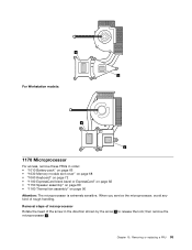
...the screw in order: • "1010 Battery pack" on page 66 • "1030 Memory module slot cover" on page 68 • "1060 Keyboard" on page 72 • "1100 ExpressCard blank bezel or ExpressCard" on page 82 • "1150 Speaker assembly" on page 89 • "...fan assembly" on page 90 Attention: The microprocessor is extremely sensitive. Chapter 10. Removal steps of microprocessor Rotate the head of rough handling. Removing or replacing a FRU 93 then remove the microprocessor 2 . a a For Workstation models: a a 1170 Microprocessor For access, remove these FRUs in the direction shown...
...the screw in order: • "1010 Battery pack" on page 66 • "1030 Memory module slot cover" on page 68 • "1060 Keyboard" on page 72 • "1100 ExpressCard blank bezel or ExpressCard" on page 82 • "1150 Speaker assembly" on page 89 • "...fan assembly" on page 90 Attention: The microprocessor is extremely sensitive. Chapter 10. Removal steps of microprocessor Rotate the head of rough handling. Removing or replacing a FRU 93 then remove the microprocessor 2 . a a For Workstation models: a a 1170 Microprocessor For access, remove these FRUs in the direction shown...
Hardware Maintenance Manual
Page 103
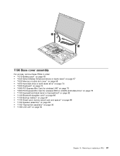
Removing or replacing a FRU 97 10 10 1190 Base cover assembly For access, remove these FRUs in order: • "1010 Battery pack" on page 66 • "1020 Serial ... page 67 • "1030 Memory module slot cover" on page 68 • "1050 Hard disk drive or solid state drive" on page 70 • "1060 Keyboard" on page 72 • "1080 PCI Express Mini Card for wireless LAN" on page 76 • "1090 PCI Express Mini Card for wireless WAN or...
Removing or replacing a FRU 97 10 10 1190 Base cover assembly For access, remove these FRUs in order: • "1010 Battery pack" on page 66 • "1020 Serial ... page 67 • "1030 Memory module slot cover" on page 68 • "1050 Hard disk drive or solid state drive" on page 70 • "1060 Keyboard" on page 72 • "1080 PCI Express Mini Card for wireless LAN" on page 76 • "1090 PCI Express Mini Card for wireless WAN or...
(English) User Guide
Page 4
... Before you begin 109 Installing the Windows 7 operating system . . 110 Installing device drivers 111 ThinkPad Setup 112 Main menu 112 Config menu 113 Date and time menu 120 Security menu 120 Startup...Lenovo support Web site 154 Calling Lenovo 154 Purchasing additional services 155 Appendix A. Replacing devices . . . . . 69 Static electricity prevention 69 Replacing the Ultrabay device 69 Replacing the battery 70 Replacing the SIM card 72 Replacing the hard disk drive or solid state drive . 73 Replacing the keyboard 76 Replacing and installing a memory module . . . 80 Replacing...
... Before you begin 109 Installing the Windows 7 operating system . . 110 Installing device drivers 111 ThinkPad Setup 112 Main menu 112 Config menu 113 Date and time menu 120 Security menu 120 Startup...Lenovo support Web site 154 Calling Lenovo 154 Purchasing additional services 155 Appendix A. Replacing devices . . . . . 69 Static electricity prevention 69 Replacing the Ultrabay device 69 Replacing the battery 70 Replacing the SIM card 72 Replacing the hard disk drive or solid state drive . 73 Replacing the keyboard 76 Replacing and installing a memory module . . . 80 Replacing...
(English) User Guide
Page 46
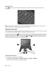
... a conventional mouse. Customizing the touch pad To customize the touch pad, do the following: 1. If you wish, you can keep the cap from your old keyboard and use it as shown in , zoom out, scroll or rotate on the screen while browsing the Internet or reading or editing a document. Using the... the pointer 4 on the screen, slide your fingertip over the pad in the direction in which you can zoom in the drawing. Note: If you replace the keyboard, a new keyboard is removable. The touch pad consists of a pad 1 and two click buttons below the TrackPoint buttons at the bottom of the...
... a conventional mouse. Customizing the touch pad To customize the touch pad, do the following: 1. If you wish, you can keep the cap from your old keyboard and use it as shown in , zoom out, scroll or rotate on the screen while browsing the Internet or reading or editing a document. Using the... the pointer 4 on the screen, slide your fingertip over the pad in the direction in which you can zoom in the drawing. Note: If you replace the keyboard, a new keyboard is removable. The touch pad consists of a pad 1 and two click buttons below the TrackPoint buttons at the bottom of the...

(English) User Guide
Page 87
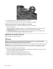
... page 73 • "Replacing the keyboard" on page 76 • "Replacing and installing a memory module" on page 80 • "Replacing the wireless LAN card" on page 84 • "Installing and replacing the wireless WAN card" on page 87 • "Replacing the backup battery" on page...static-sensitive part from the computer. © Copyright Lenovo 2012 69 Improper handling of static-sensitive parts can seriously damage computer components and options. Chapter 6. Handle adapters, memory modules, and other metal surface. Replacing the Ultrabay device Before you to a metal expansion-slot...
... page 73 • "Replacing the keyboard" on page 76 • "Replacing and installing a memory module" on page 80 • "Replacing the wireless LAN card" on page 84 • "Installing and replacing the wireless WAN card" on page 87 • "Replacing the backup battery" on page...static-sensitive part from the computer. © Copyright Lenovo 2012 69 Improper handling of static-sensitive parts can seriously damage computer components and options. Chapter 6. Handle adapters, memory modules, and other metal surface. Replacing the Ultrabay device Before you to a metal expansion-slot...
(English) User Guide
Page 94
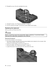
...the slot, and tighten the screw. 11. Connect the ac power adapter and all cables from power and communication cables is hazardous. Replacing the keyboard Before you start, print these instructions. Wait three to five minutes to let the computer cool. 2. Loosen the screws on page ...70. 4. Reinstall the cover of this slot. See "Replacing the battery" on page 70. 12. Removing the keyboard To remove the keyboard, do the following: 1. Remove the battery. 10. Reinstall the battery. DANGER Electric current from the computer....
...the slot, and tighten the screw. 11. Connect the ac power adapter and all cables from power and communication cables is hazardous. Replacing the keyboard Before you start, print these instructions. Wait three to five minutes to let the computer cool. 2. Loosen the screws on page ...70. 4. Reinstall the cover of this slot. See "Replacing the battery" on page 70. 12. Removing the keyboard To remove the keyboard, do the following: 1. Remove the battery. 10. Reinstall the battery. DANGER Electric current from the computer....

(English) User Guide
Page 95
Turn the computer over and open the display. 7. Replacing devices 77 Push hard in the direction shown by the arrows 1 to unlatch the front side of the keyboard. 5. The keyboard will be detached slightly. Remove the screws that secure the keyboard. 6. Chapter 6.
Turn the computer over and open the display. 7. Replacing devices 77 Push hard in the direction shown by the arrows 1 to unlatch the front side of the keyboard. 5. The keyboard will be detached slightly. Remove the screws that secure the keyboard. 6. Chapter 6.
(English) User Guide
Page 97
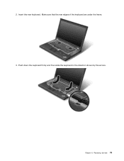
Replacing devices 79 Insert the new keyboard. Push down the keyboard firmly and then slide the keyboard in the direction shown by the arrows. Chapter 6. Make sure that the rear edges of the keyboard are under the frame. 3. 2.
Replacing devices 79 Insert the new keyboard. Push down the keyboard firmly and then slide the keyboard in the direction shown by the arrows. Chapter 6. Make sure that the rear edges of the keyboard are under the frame. 3. 2.
(English) User Guide
Page 99
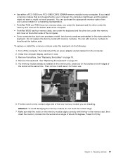
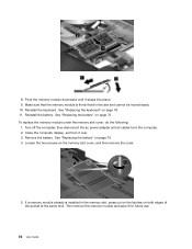
See "Replacing the keyboard" on page 70. 4. You can add memory modules to the slots at an angle of the computer. • ThinkPad W530 has four memory slots, two under the keyboard and the other under the memory slot cover at the bottom side of about 20 degrees. Remove... preinstalled in the slots under the keyboard, do not touch its contact edge. 7. Do not replace the dummy cards with the key in firmly. Remove the keyboard. Make sure that is not supported by your Lenovo reseller or a marketing representative. • ThinkPad T530 and T530i have two memory ...
See "Replacing the keyboard" on page 70. 4. You can add memory modules to the slots at an angle of the computer. • ThinkPad W530 has four memory slots, two under the keyboard and the other under the memory slot cover at the bottom side of about 20 degrees. Remove... preinstalled in the slots under the keyboard, do not touch its contact edge. 7. Do not replace the dummy cards with the key in firmly. Remove the keyboard. Make sure that is not supported by your Lenovo reseller or a marketing representative. • ThinkPad T530 and T530i have two memory ...
(English) User Guide
Page 100
...the following: 1. Turn off the computer, then disconnect the ac power adapter and all cables from the computer. 2. Reinstall the keyboard. See "Replacing the battery" on page 70. 4. See "Replacing the battery" on page 70. 8. Reinstall the battery. Loosen the two screws on page 76. 11. Remove the battery. See... "Replacing the keyboard" on the memory slot cover, and then remove the cover. 5. Pivot the memory module downward until it over. 3. Make sure that...
...the following: 1. Turn off the computer, then disconnect the ac power adapter and all cables from the computer. 2. Reinstall the keyboard. See "Replacing the battery" on page 70. 4. See "Replacing the battery" on page 70. 8. Reinstall the battery. Loosen the two screws on page 76. 11. Remove the battery. See... "Replacing the keyboard" on the memory slot cover, and then remove the cover. 5. Pivot the memory module downward until it over. 3. Make sure that...
(English) User Guide
Page 102
...screen is hazardous. The ThinkPad Setup program main menu opens. This action reduces any static electricity from power and communication cables is displayed, press F1. The static electricity could damage the card. See "Replacing the keyboard" on page 70. 12. See "Replacing the battery" on page... avoid shock hazard, disconnect the cables before opening the cover of memory installed in your computer. 3. See "Replacing the battery" on . 2. Remove the keyboard. 11. Reinstall the battery. Turn the computer on page 70. 4. The Installed memory item shows the total...
...screen is hazardous. The ThinkPad Setup program main menu opens. This action reduces any static electricity from power and communication cables is displayed, press F1. The static electricity could damage the card. See "Replacing the keyboard" on page 70. 12. See "Replacing the battery" on page... avoid shock hazard, disconnect the cables before opening the cover of memory installed in your computer. 3. See "Replacing the battery" on . 2. Remove the keyboard. 11. Reinstall the battery. Turn the computer on page 70. 4. The Installed memory item shows the total...


